Mitsubishi Electric LGH-F300RVX2-E Handbook
Hide thumbs
Also See for LGH-F300RVX2-E:
- Installation instructions manual (60 pages) ,
- Operating instructions manual (9 pages)
Table of Contents
Advertisement
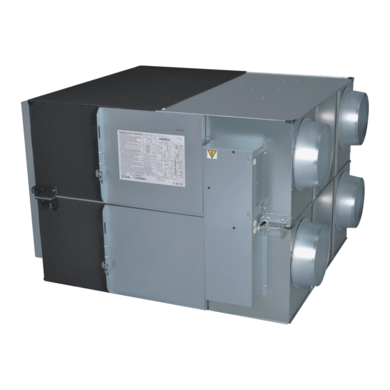
LOSSNAY ENERGY RECOVERY VENTILATOR
HANDBOOK
MODELS
LGH-F300RVX2-E
LGH-F380RVX2-E
LGH-F470RVX2-E
LGH-F600RVX2-E
LGH-F940RVX2-E
LGH-F1200RVX2-E
Remote controller
PZ-62DR-EA
PZ-43SMF-E
Filter
(For replacement)
PZ-50RF
-E
9
PZ-65RF
-E
9
PZ-80RF
-E
9
PZ-100RF
9
Warning:
Repair work must be performed by the manufacturer, its service
agent or a similarly qualified person in order to avoid hazards.
(Optional)
-E
February 2022
Nameplate
Nameplate
No. U307-A
Advertisement
Table of Contents

Related Manuals for Mitsubishi Electric LGH-F300RVX2-E


Summary of Contents for Mitsubishi Electric LGH-F300RVX2-E
- Page 1 February 2022 No. U307-A LOSSNAY ENERGY RECOVERY VENTILATOR HANDBOOK MODELS Nameplate LGH-F300RVX2-E LGH-F380RVX2-E LGH-F470RVX2-E LGH-F600RVX2-E LGH-F940RVX2-E Nameplate LGH-F1200RVX2-E Remote controller (Optional) PZ-62DR-EA PZ-43SMF-E Filter (For replacement) PZ-50RF PZ-65RF PZ-80RF PZ-100RF Warning: Repair work must be performed by the manufacturer, its service...
-
Page 2: Table Of Contents
7-1 Service flowchart ..................13 13-14 7-2 Check Details ..................14 14-39 8. Overhauling procedures ..............40 40-53 9. Parts catalog ................. 54 54-102 LGH-F300RVX2-E ..................55 55-62 LGH-F380RVX2-E ..................63 63-70 LGH-F470RVX2-E ..................71 71-78 LGH-F600RVX2-E ..................79 79-86 LGH-F940RVX2-E .................. -
Page 3: Safety Precautions
1. Safety precautions Read the following precautions thoroughly before the maintenance, and then inspect and repair the product in a safe manner. The types and levels of danger that may arise if the product is handled improperly are described with the warning symbols shown below. -
Page 4: Changed Points
LGH-F600RVX2-E LGH-F600RVX-E LGH-F940RVX2-E – LGH-F1200RVX2-E LGH-F1200RVX-E PZ-62DR-EA PZ-61DR-E 3. Specifications LGH-F300RVX2-E, LGH-F380RVX2-E, LGH-F470RVX2-E, LGH-F600RVX2-E, Model name LGH-F940RVX2-E, LGH-F1200RVX2-E Heat exchange system Energy recovery ventilating system Heat exchanger material Special treated paper plate heat exchanger Cladding Galvanized steel sheet Heat insulation material... - Page 5 * Temperature Exchange efficiency (%) are average of summer and winter condition. * Mitsubishi Electric measures products according to ISO 16494:2014, therefore characteristic values are mea- sured by chamber method. * On-site commissioning measurements by pitot tube method could be as much 20% different from ISO test room conditions.
-
Page 6: Outside Dimensions
4. Outside dimensions LGH-F300RVX2-E, LGH-F380RVX2-E, LGH-F470RVX2-E, LGH-F600RVX2-E Position where duct direction change is possible By-pass damper plate Ceiling suspension fixture Air exhaust fan (4-1/2 X 13/16 (4-13 X 20) oval) (exhaust air outlet) (return air) (outside air intake) (supply air) - Page 7 LGH-F940RVX2-E, LGH-F1200RVX2-E By-pass damper plate 1 37/64 1 37/64 Ceiling suspension fixture (40) (40) 39 3/4 (1010) Air exhaust fan (4-9/16 X 1 3/16 (4-15 X 30) oval) (return air) (exhaust air outlet) (outside air intake) (supply air) 15 29/32 Core, air filter, Inspection (404)
- Page 8 -E, PZ-65RF -E, PZ-80RF -E, PZ-100RF The number of Dimension filters per set Model Applicable model Supply Exhaust 18 1/2 7 13/64 25/32 PZ-50RF LGH-F300RVX2-E (470) (183) (20) 17 3/64 8 37/64 25/32 PZ-65RF LGH-F380RVX2-E (433) (218) (20) LGH-F470RVX2-E 17 3/4...
-
Page 9: Electrical Wiring Diagrams
5. Electrical wiring diagrams LGH-F300RVX2-E, LGH-F380RVX2-E, LGH-F470RVX2-E, LGH-F600RVX2-E * Wiring for TM1, TM2, TM3, TM4, and TB5 shown in dotted lines are field work. * Be sure to connect the earth wire. * An all pole electric leakage isolator must be installed. - Page 10 LGH-F940RVX2-E, LGH-F1200RVX2-E * Wiring for TM1, TM2, TM3, TM4, and TB5 shown in dotted lines are field work. * Be sure to connect the earth wire. * An all pole electric leakage isolator must be installed. * Always use an isolator for the main power connection. Lossnay unit Power circuit board Power circuit board...
-
Page 11: Circuit Board Diagrams
6. Circuit board diagrams Circuit board diagrams and check points (1) Control circuit board Caution: Before servicing (including replacing the circuit boards), be sure to turn off the power supply isolator and check that all the LEDs on the control circuit board and power circuit board are not lit. A large- capacity electrolytic capacitor on the circuit board may carry voltage for several minutes after the iso- lator is turned off. - Page 12 There are three types of the power circuit board. The type of the power circuit board varies depending on the model of the Lossnay unit. When replacing the circuit board, use the applicable circuit board according to the table below. Power circuit board Lossnay unit LG-X08DC-P4 LGH-F300RVX2-E, LGH-F380RVX2-E LG-X08DC-P6 LGH-F470RVX2-E, LGH-F600RVX2-E LG-X08DC-P5 LGH-F940RVX2-E, LGH-F1200RVX2-E LG-X08DC-P6...
-
Page 13: Troubleshooting
• When carrying out wiring, power supply to M-NET must be turned off, otherwise it will cause a malfunction. 7-1 Service flowchart After checking the check items below, follow the troubleshooting for servicing. Applicable Device Applicable Model LGH-F300RVX2-E, LGH-F380RVX2-E, LGH-F470RVX2-E, Lossnay Heat recovery Ventilator LGH-F600RVX2-E, LGH-F940RVX2-E, LGH-F1200RVX2-E Lossnay Remote Controller PZ-62DR-EA, PZ-43SMF-E... -
Page 14: Check Details
Lossnay does not start properly. (1) Failure mode 1: Lossnay does not work. Lossnay does not work in trial operation, or Lossnay stops working during use. (2) Failure mode 2: The remote controller does not The remote controller does not work. work. - Page 15 [2] Transmission cables (remote controller transmission cable, M-NET transmission cable, external input/output signal cable, and connection cable for IT communication appliances) Check Item Corrective action 1 Are the designated cables used for the remote control- Use the designated transmission cables. ler transmission cable and M-NET transmission cable? (See Table 2-1 and Table 2-2.) 2 Are the designated cables used for the external input/...
- Page 16 Table 2-3 External input/output specifications Terminal or Signal Total Function Name connector on Materials Used specifications extension the circuit board External control input Level/pulse Twisted lead AWG 20 (0.5 mm 547 yd. TM2 [Y] [Z] (volt-free contact) (Note 4) (Note 1) to AWG 15 (1.5 mm (500 m) External control input...
- Page 17 [3] Monitor output signal cable Check Item Corrective action 1 Is the signal cable wired by multicore cable? Wire the cable using a 2-core cable. 2 Are the signal cables and transmission cables wired Wire the signal cables away from the transmission in the same piping duct? cables.
- Page 18 [5] LED Indications on the circuit boards Contents Check Item Corrective action LED1 Lossnay unit error Blinking: Starting up, error occurred In the case of an error, see Failure (green) indicator Mode 4. Lit: During delay operation Lossnay operates after the delay time has passed.
- Page 19 Individual function check items [6] If Lossnay does not work in the trial operation, or if Lossnay stops working during use, check the following items. Problem Factor Corrective action 1 The fan does not The connectors between the Check the connector (CN9) for the exhaust fan operate even fan motor and circuit board are motor and the connector (CN10) for the supply fan...
- Page 20 Problem Factor Corrective action 3 [When wall-mounted sensor setting is set Check the setting. type CO sensor incorrectly. • When the function setting (No. 66) of PZ-62DR-EA PZ-70CSW-E is is set to “0”, the function selection switches used] (SW5-6 to SW5-8) on the Lossnay circuit board The LED display should be: SW5-6 ON, SW5-7 OFF, SW5-8 OFF lamps of the CO...
- Page 21 Problem Factor Corrective action 6 Even though the The indoor negative pressure Check the function selection switches (SW2-4 and remote controller is setting or the indoor positive SW2-5) on the circuit board or the function settings operated to change pressure setting is set. (No.
- Page 22 Problem Factor Corrective action 10 Even though the The outdoor temperature is When the outdoor temperature is 46.4°F (8°C) remote controller is 46.4°F (8°C) or lower. or lower, the ventilation mode is fixed to the Heat operated to change recovery mode. the ventilation mode, The signal is input to the Check the Bypass mode switching input (CN26...
- Page 23 Problem Factor Corrective action 13 Actual fan speed The signal is input to the fan Check the fan speed input (CN17). of the Lossnay unit speed input (CN17). (See the Lossnay Operating/Installation differs from the fan Instructions or PZ-62DR-E Instruction Book.) speed set with the The signal (0 to 10 V DC) is Check the fan speed switching input (CN26 [4] [5]).
- Page 24 Problem Factor Corrective action 18 When the supply The Lossnay unit is operating During the intermittent operation, the exhaust fan fan is stopped, the in the protective mode (inter- operates at fan speed 4. exhaust fan oper- mittent operation). (Outdoor ates at the higher temperature is 23°F (-5°C) or fan speed than...
- Page 25 <Fig. 6-1 Check of Wi-Fi interface> Start There is a problem in communication between the Lossnay and the Wi-Fi interface. Is the UNIT lamp on the Wi-Fi interface blinking? [1] Read the QR code of the Wi-Fi interface, and check that the SERVICE REFERENCE is NOT "MAC-567IF-E".
- Page 26 (2) Failure mode 2: The remote controller does not work. If the remote controller does not work, check the following items. [1] PZ-62DR-EA Problem Factor Corrective action 1 Nothing is displayed The power of the Lossnay unit is Check the items described in (1) [1]. on the remote not ON.
- Page 27 Problem Factor Corrective action 2 “H0” is displayed on The remote controller is starting up. The remote controller displays “H0” during the remote controller. start-up for a maximum of one minute. 3 It takes time for the The Lossnay unit is starting up. The remote controller is not fed with power remote controller to during start-up of the Lossnay unit for a...
- Page 28 Individual check items If the system cannot be started/stopped using the remote controller, check the following items. [1] PZ-62DR-EA Problem Factor Corrective action 1 Some Lossnay units in The power of the Lossnay unit Check the items described in (1) [1]. the group do not operate.
- Page 29 Problem Factor Corrective action 6 Even though the function The indoor, outdoor, and/or • Outdoor temperature display range: 35.6°F settings (No. 36, 37 and/ supply air temperature are out- (2°C) to 96.8°F (36°C) or 39) of PZ-62DR-EA are side the display range. •...
- Page 30 [2] Interlocking with air conditioners (Mr. Slim indoor unit or City Multi indoor unit) or external devices Problem Factor Corrective action 1 Lossnay interlock The power of the Lossnay unit is not Check the items described in (1) [1]. settings cannot be performed Faulty connection of the remote con- Check the items described in (1) [2].
- Page 31 [3] System controller Problem Factor Corrective action 1 The group of The power of the Lossnay unit is Check the items described in (1) [1]. Lossnay cannot be not ON. set with the system M-NET transmission cable is con- Connect the M-NET transmission cable to the controller.
- Page 32 (4) Failure mode 4: Error code and LED display An error code displayed on the remote controller (PZ-62DR-EA, PZ-43SMF-E) or the M-NET controller, and blinking or illumination of LED1 (green) or LED2 (red) on the circuit board show the type of an error. The LED blink interval is 0.25 seconds for both on and off.
- Page 33 Error LED1 LED2 Symptom Cause Corrective action Code (green) (red) 4101 Overcurrent Shorting between the remote control- Check the remote controller wiring. blinks error of the ler terminals remote con- The group contains two or more Loss- Set unique addresses to these troller terminal nay units with the same address.
- Page 34 Error LED1 LED2 Symptom Cause Corrective action Code (green) (red) 4116 Abnormal Faulty connection of the exhaust fan Check the connector (CN9) blinks rotation of the motor connector (CN9) on the power connection. exhaust fan circuit board motor <For LGH-F300 to 600 types> blinks (Centrifugal fan Faulty connection of the connectors...
- Page 35 Error LED1 LED2 Symptom Cause Corrective action Code (green) (red) 5102 Return air Faulty connection of the thermistor Check the connector (CN5) blinks (RA) thermis- connector (CN5) on the control cir- connection. tor related cuit board error Thermistor failure Disconnect the connector (CN5), and check the resistance of the thermistor.
- Page 36 Error LED1 LED2 Symptom Cause Corrective action Code (green) (red) 6602 Transmission Faulty connection of the M-NET Check the items described in (1) blinks error transmission cable [2]. (transmis- Wiring was performed with power Restart the system after complet- • sion proces- still supplied to the M-NET trans- ing wiring.
- Page 37 Error LED1 LED2 Symptom Cause Corrective action Code (green) (red) 6606 Transmission/ Faulty connection of the M-NET Check the items described in (1) blinks reception error transmission cable [2]. (communica- Wiring was performed with power Restart the system after complet- •...
- Page 38 Error LED1 LED2 Symptom Cause Corrective action Code (green) (red) 6831 PZ-62DR-EA Faulty connection of the Check the items described in (1) [2]. blinks communica- PZ-62DR-EA transmission cable If the error re-occurs, check for tion error (no noise on the transmission cable. reception) If the above does not correct the problem, replace the Lossnay con-...
- Page 39 [2] If the resistance between the motor leads is significantly different from the values specified in the table below *Before measuring the resistance, the motor connectors must be disconnected from the circuit board. <LGH-F300RVX2-E, LGH-F380RVX2-E> Supply fan motor Pin No.
-
Page 40: Overhauling Procedures
Always wear a pair of gloves when servicing. <External and internal view of the product> Names within angle brackets < > are part names listed in the parts catalog. Models LGH-F300RVX2-E, LGH-F380RVX2-E, LGH-F470RVX2-E, LGH-F600RVX2-E Lossnay core holder Control box <Core guide>... - Page 41 (1) Turning power off [1] Shut down the unit. [2] Turn off the power supply isolator. Precaution When servicing, power supply to M-NET must be turned off. Live-line working may cause a circuit board failure. ( 2 ) Fan parts Control box cover [1] Remove the black screws (three special screws 4×8, indicated by...
- Page 42 [4] Slide the fix piece to the left side. Fix piece [5] Pull out the hinge, and open the maintenance cover. Hinge Maintenance cover [6] Draw the Lossnay cores (with filters) from the main unit. Filter Lossnay core [7] Remove the screws (one special screw M4, indicated ), and remove the core guides from the unit.
- Page 43 Separator [9] Remove the screws ( ), and draw the fan assembly out from the main unit. Six PTT screws 5×10, indicated by For LGH-F300RVX2-E For LGH-F380RVX2-E to LGH-F1200RVX2-E Air supply fan assembly Air supply fan assembly *The figure shows LGH-F470RVX2-E.
- Page 44 ( 3 ) Terminal block parts [1] Remove the control box cover. → See (2) [1]. [2] Check that LED4 (red) on the control circuit board is Control circuit board OFF, and then disconnect the connectors (indicated by ) from the control circuit board. [3] Remove the screw (one PPT screw 4×20, indicated by LED4 CN14...
- Page 45 (4) Control parts (For LGH-F300RVX2-E to LGH-F600RVX2-E) Precaution Before replacing the circuit boards, see (6) Procedures for replacing the circuit boards (page 49). [1] Remove the control box cover. → See (2) [1]. [2] Check that LED4 (red) on the control circuit board is...
- Page 46 [5] Remove the screws (two PT screws 4x8, indicated by ), and slide the power circuit board to remove it. Power circuit board [6] Remove the sub control base. → See (3) [4]. [7] Disconnect the connectors (indicated by ) from the Reactor reactor.
- Page 47 (5) Control parts (For LGH-F940RVX2-E and LGH-F1200RVX2-E) Precaution Before replacing the circuit boards, see (6) Procedures for replacing the circuit boards (page 49). When removing only the control circuit board [1] Remove the black screws (three special screws 4×8, indicated by ) to remove the control cover.
- Page 48 When removing the power circuit boards or reactors [1] Remove the screws (eight PT screws 4×8, Control box cover indicated by ) to remove the control box cover. [2] Remove the circuit boards and reactors. Power circuit board (upper) Reactor [Upper unit] a.
- Page 49 (6) Procedures for replacing the circuit boards Notes • Before removing the circuit boards for replacement, check the following Steps 1 and 2. • When the Lossnay remote controller PZ-62DR-EA is connected, be sure to replace the circuit boards as described in the Steps.
- Page 50 Removing the circuit boards • For the working precautions, see page 40. • For removing the circuit boards, see (4) Control parts (For LGH-F300RVX2-E to LGH-F600RVX2-E) (page 45) or (5) Control parts (For LGH-F940RVX2-E and LGH-F1200RVX2-E) (page 47). Attaching the circuit boards...
- Page 51 Step Details Check item Function setting with PZ-62DR-EA When PZ-62DR-EA is connected, according to the function status record data pre- Address pared in Step 2, set the function settings with PZ-62DR-EA. setting If PZ-62DR-EA is not connected, skip this step and proceed to Step 7. Function To perform function settings with PZ-62DR-EA, see the Lossnay Operating/ setting...
- Page 52 □ □ □ : Factory setting Model selection switch Note: SW6 setting differs according to the model. □ □ Model SW6-1 SW6-2 SW6-3 SW6-4 SW6-5 SW6-6 □ □ LGH-F300RVX2-E □ □ LGH-F380RVX2-E □ □ LGH-F470RVX2-E □ □ LGH-F600RVX2-E □ □...
- Page 53 [3] Function settings Enter the setting data of the functions set with PZ-62DR-EA. Function No. Setting Data Function No. Setting Data Function No. Setting Data Function No. Setting Data (15) (10) (15) (10) ( ) : Factory setting [4] External input/output Enter the usage of the external input/output on the control circuit board.
-
Page 54: Parts Catalog
9. Parts catalog Please note the following when using the parts catalog. 1. When ordering parts, the part number, part name, and the number of parts are required. 2. It may take time for you to receive the parts. Make an inquiry about a rush order. 3. -
Page 55: Lgh-F300Rvx2-E
LGH-F300RVX2-E Structural parts 4 pcs. 4 pcs. 2 pcs. 4 pcs. 4 pcs. 4 pcs. 2 pcs. 4 pcs. 2 pcs. Screw cap 16 pcs. 4 pcs. 6 pcs. <Standard screws> Symbol Screw name PT screw 6x12 PTT screw 4x8... - Page 56 Structural parts LGH-F300RVX2-E Critical Q'ty Name of part Parts No. Remarks pcs/unit safety Maintenance cover W50 013 709 Special screw M4 W00 000 101 Core guide L W50 013 382 Lossnay core W50 004 719 With the filter stoppers...
- Page 57 Fan parts Air exhaust fan assembly 2 pcs. 2 pcs. 4 pcs. 4 pcs. 4 pcs. 4 pcs. 32 31 Air supply fan assembly <Standard screws> Symbol Screw name PTT screw 4x8 PTT screw 5x10 ─ 57 ─ LGH-F300RVX2-E...
- Page 58 Fan parts LGH-F300RVX2-E Critical Q'ty Name of part Parts No. Remarks pcs/unit safety Special nut (M8) W00 000 121 Left-handed Tab washer W00 000 134 Centrifugal fan W50 013 481 Dia. 8 3/4 inch (220 mm) Special washer (10) W50 003 478 Outer dia.
- Page 59 Control parts <Standard screws> Symbol Screw name PTT screw 4x8 PPT screw 3x8 PT screw 4x8 PPT screw 4x20 ─ 59 ─ LGH-F300RVX2-E...
- Page 60 Control parts LGH-F300RVX2-E Critical Q'ty Name of part Parts No. Remarks pcs/unit safety Control box cover W50 019 707 Circuit board W50 021 171 Control PCB fix plate W50 021 706 Sub control base W50 021 715 Circuit board...
- Page 61 CN119 LED1 Volt-free contact LED2 CN113 CN19 SW12 SW11 CN12 CN14 LED5 TAB1 TAB2 LINE FILTER CN34 CN35 CN23 LINE FILTER REACTOR (RA) (OA) Power supply terminal Isolator (Field supply) POWER SUPPLY 208–230 V / 60Hz ─ 61 ─ LGH-F300RVX2-E...
- Page 62 Wiring parts LGH-F300RVX2-E Critical Q'ty Name of part Parts No. Remarks pcs/unit safety Thermistor W50 023 167 OA・RA set Lead wire W50 021 214 Lead wire W50 004 231 3 15/16 inch (100 mm) ─62─...
-
Page 63: Lgh-F380Rvx2-E
LGH-F380RVX2-E Structural parts 4 pcs. 4 pcs. 2 pcs. 4 pcs. 4 pcs. 4 pcs. 2 pcs. 4 pcs. 2 pcs. Screw cap 16 pcs. 4 pcs. 6 pcs. <Standard screws> Symbol Screw name PT screw 6x12 PTT screw 4x8 PT screw 5x10 PTT screw 4x6 shows accessory parts. - Page 64 Structural parts LGH-F380RVX2-E Critical Q'ty Name of part Parts No. Remarks pcs/unit safety Maintenance cover W50 013 710 Special screw M4 W00 000 101 Core guide L W50 013 383 Lossnay core W50 023 710 With the filter stoppers Filter W50 023 718 ...
- Page 65 Fan parts Air exhaust fan assembly 2 pcs. 6 pcs. 4 pcs. 6 pcs. 4 pcs. 2 pcs. Air supply fan assembly <Standard screws> Symbol Screw name PTT screw 5x10 ─ 65 ─ LGH-F380RVX2-E...
- Page 66 Fan parts LGH-F380RVX2-E Critical Q'ty Name of part Parts No. Remarks pcs/unit safety Special Nut (M10) W00 000 195 Left-handed Tab washer W50 013 712 Centrifugal fan W50 013 482 Dia. 9 5/8 inch (245 mm) Special washer (10) W50 003 478 Outer dia.
- Page 67 Control parts <Standard screws> Symbol Screw name PTT screw 4x8 PPT screw 3x8 PT screw 4x8 PPT screw 4x20 ─ 67 ─ LGH-F380RVX2-E...
- Page 68 Control parts LGH-F380RVX2-E Critical Q'ty Name of part Parts No. Remarks pcs/unit safety Control box cover W50 019 707 Circuit board W50 021 171 Control PCB fix plate W50 021 706 Sub control base W50 021 715 Circuit board W50 021 172 Power ...
- Page 69 Wiring parts Lossnay unit Control circuit board Power circuit board LINE FILTER CN105 CN32 Exhaust fan motor Monitor output CN50 CN26 CN17 PZ-62DR-EA 2nd remote controller LED6 (Max. 2 controllers) Supply fan motor 2nd Lossnay unit LED3 (Max. 15 units) LED4 CN10 M-NET transmission cable...
- Page 70 Wiring parts LGH-F380RVX2-E Critical Q'ty Name of part Parts No. Remarks pcs/unit safety Thermistor W50 023 167 OA・RA set Lead wire W50 021 214 Lead wire W50 004 231 3 15/16 inch (100 mm) ─70─...
-
Page 71: Lgh-F470Rvx2-E
LGH-F470RVX2-E Structural parts 4 pcs. 4 pcs. 2 pcs. 4 pcs. 4 pcs. 4 pcs. 2 pcs. 2 pcs. 4 pcs. 2 pcs. Screw cap 16 pcs. 4 pcs. 6 pcs. <Standard screws> Symbol Screw name PT screw 6x12 PTT screw 4x8 PT screw 5x10 shows accessory parts. - Page 72 Structural parts LGH-F470RVX2-E Critical Q'ty Name of part Parts No. Remarks pcs/unit safety Maintenance cover W50 013 711 Special screw M4 W00 000 101 Core guide L W50 013 384 Lossnay core W50 004 720 With the filter stoppers Filter W50 023 719 ...
- Page 73 Fan parts Air exhaust fan assembly e (6 pcs.) e (6 pcs.) 4 pcs. 4 pcs. Air supply fan assembly <Standard screws> Symbol Screw name PTT screw 4x25 PTT screw 5x10 ─ 73 ─ LGH-F470RVX2-E...
- Page 74 Fan parts LGH-F470RVX2-E Critical Q'ty Name of part Parts No. Remarks pcs/unit safety Special nut (M12) W00 000 117 Left-handed Tab washer W50 004 730 Centrifugal fan W50 004 482 Dia. 9 5/8 inch (245 mm) Washer (12) W00 000 123 Outer dia.
- Page 75 Control parts <Standard screws> Symbol Screw name PTT screw 4x8 PPT screw 3x8 PT screw 4x8 PPT screw 4x20 ─ 75 ─ LGH-F470RVX2-E...
- Page 76 Control parts LGH-F470RVX2-E Critical Q'ty Name of part Parts No. Remarks pcs/unit safety Control box cover W50 019 707 Circuit board W50 021 171 Control PCB fix plate W50 021 706 Sub control base W50 021 715 Circuit board W50 023 171 Power ...
- Page 77 Wiring parts Lossnay unit Control circuit board Power circuit board CN105 CN32 Exhaust fan motor Monitor output CN50 CN26 CN17 PZ-62DR-EA 2nd remote controller LED6 (Max. 2 controllers) Supply fan motor 2nd Lossnay unit LED3 (Max. 15 units) LED4 CN10 M-NET transmission cable Shielded wire CN114...
- Page 78 Wiring parts LGH-F470RVX2-E Critical Q'ty Name of part Parts No. Remarks pcs/unit safety Thermistor W50 023 167 OA・RA set Lead wire W50 021 214 Lead wire W50 004 231 3 15/16 inch (100 mm) ─78─...
-
Page 79: Lgh-F600Rvx2-E
LGH-F600RVX2-E Structural parts 4 pcs. 4 pcs. 2 pcs. 4 pcs. 4 pcs. 4 pcs. 2 pcs. 2 pcs. 4 pcs. 2 pcs. Screw cap 16 pcs. 4 pcs. 6 pcs. <Standard screws> Symbol Screw name PT screw 6x12 PTT screw 4x8 PT screw 5x10 shows accessory parts. - Page 80 Structural parts LGH-F600RVX2-E Critical Q'ty Name of part Parts No. Remarks pcs/unit safety Maintenance cover W50 013 711 Special screw M4 W00 000 101 Core guide L W50 013 385 Lossnay core W50 004 721 With the filter stoppers Filter W50 023 720 ...
- Page 81 Fan parts Air exhaust fan assembly e (6 pcs.) e (6 pcs.) 4 pcs. 4 pcs. Air supply fan assembly <Standard screws> Symbol Screw name PTT screw 4x25 PTT screw 5x10 ─ 81 ─ LGH-F600RVX2-E...
- Page 82 Fan parts LGH-F600RVX2-E Critical Q'ty Name of part Parts No. Remarks pcs/unit safety Special nut (M12) W00 000 117 Left-handed Tab washer W50 004 730 Centrifugal fan W50 004 482 Dia. 9 5/8 inch (245 mm) Washer (12) W00 000 123 Outer dia.
- Page 83 Control parts <Standard screws> Symbol Screw name PTT screw 4x8 PPT screw 3x8 PT screw 4x8 PPT screw 4x20 ─ 83 ─ LGH-F600RVX2-E...
- Page 84 Control parts LGH-F600RVX2-E Critical Q'ty Name of part Parts No. Remarks pcs/unit safety Control box cover W50 019 707 Circuit board W50 021 171 Control PCB fix plate W50 021 706 Sub control base W50 021 715 Circuit board W50 023 171 Power ...
- Page 85 Wiring parts Lossnay unit Control circuit board Power circuit board CN105 CN32 Exhaust fan motor Monitor output CN50 CN26 CN17 PZ-62DR-EA 2nd remote controller LED6 (Max. 2 controllers) Supply fan motor 2nd Lossnay unit LED3 (Max. 15 units) LED4 CN10 M-NET transmission cable Shielded wire CN114...
- Page 86 Wiring parts LGH-F600RVX2-E Critical Q'ty Name of part Parts No. Remarks pcs/unit safety Thermistor W50 023 168 OA・RA set Lead wire W50 021 214 Lead wire W50 004 231 3 15/16 inch (100 mm) ─86─...
-
Page 87: Lgh-F940Rvx2-E
LGH-F940RVX2-E Structural parts <Standard screws> 4 pcs. Symbol Screw name 4 pcs. PT screw 6x12 PTT screw 4x8 4 pcs. 4 pcs. 2 pcs. 2 pcs. 2 pcs. 2 pcs. 4 pcs. 2 pcs. 4 pcs. 2 pcs. 2 pcs. 2 pcs. - Page 88 Structural parts LGH-F940RVX2-E Critical Q'ty Name of part Parts No. Remarks pcs/unit safety Maintenance cover W50 013 711 Special screw M4 W00 000 101 Core guide L W50 013 384 Filter W50 023 719 Filter stopper W50 016 711 Lossnay core W50 004 720 With the filter stoppers...
- Page 89 Fan parts Air exhaust fan assembly Upper unit c (6 pcs.) c (6 pcs.) 4 pcs. Air supply fan assembly 4 pcs. Air exhaust fan assembly Lower unit c (6 pcs.) c (6 pcs.) 4 pcs. Air supply fan assembly 4 pcs.
- Page 90 Fan parts LGH-F940RVX2-E Critical Q'ty Name of part Parts No. Remarks pcs/unit safety Special nut (M12) W00 000 117 Left-handed Tab washer W50 004 730 Centrifugal fan W50 004 482 Dia. 9 5/8 inch (245 mm) Washer (12) W00 000 123 Outer dia.
- Page 91 Control parts 6 pcs. <Standard screws> Symbol Screw name PTT screw 4x8 PPT screw 3x8 PT screw 4x8 PPT screw 4x20 ─ 91 ─ LGH-F940RVX2-E...
- Page 92 Control parts LGH-F940RVX2-E Critical Q'ty Name of part Parts No. Remarks pcs/unit safety Cord bush W00 000 277 Bush W00 000 278 Circuit board W50 023 172 Power, Upper PCB case W50 021 380 Reactor W50 004 180 AC6.5A ...
- Page 93 Wiring parts Lossnay unit Control circuit board Power circuit board Power circuit board (Lower unit) (Upper unit) CN105 CN32 Exhaust fan Exhaust fan Monitor output motor motor CN50 CN26 CN17 PZ-62DR-EA 2nd remote controller (Max. 2 controllers) Supply fan Supply fan 2nd Lossnay unit LED6 LED6...
- Page 94 Wiring parts LGH-F940RVX2-E Critical Q'ty Name of part Parts No. Remarks pcs/unit safety Lead wire W50 023 213 Lead wire W50 021 214 Thermistor W50 023 167 OA・RA set Lead wire W50 004 231 3 15/16 inch (100 mm) ─94─...
-
Page 95: Lgh-F1200Rvx2-E
LGH-F1200RVX2-E Structural parts <Standard screws> 4 pcs. Symbol Screw name 4 pcs. PT screw 6x12 PTT screw 4x8 4 pcs. 4 pcs. 2 pcs. 2 pcs. 2 pcs. 2 pcs. 4 pcs. 2 pcs. 4 pcs. 2 pcs. 2 pcs. 2 pcs. - Page 96 Structural parts LGH-F1200RVX2-E Critical Q'ty Name of part Parts No. Remarks pcs/unit safety Maintenance cover W50 013 711 Special screw M4 W00 000 101 Core guide L W50 013 385 Filter W50 023 720 Filter stopper W50 016 711 Lossnay core W50 004 721 With the filter stoppers...
- Page 97 Fan parts Air exhaust fan assembly Upper unit c (6 pcs.) c (6 pcs.) 4 pcs. Air supply fan assembly 4 pcs. Air exhaust fan assembly Lower unit c (6 pcs.) c (6 pcs.) 4 pcs. Air supply fan assembly 4 pcs.
- Page 98 Fan parts LGH-F1200RVX2-E Critical Q'ty Name of part Parts No. Remarks pcs/unit safety Special nut (M12) W00 000 117 Left-handed Tab washer W50 004 730 Centrifugal fan W50 004 482 Dia. 9 5/8 inch (245 mm) Washer (12) W00 000 123 Outer dia.
- Page 99 Control parts 6 pcs. <Standard screws> Symbol Screw name PTT screw 4x8 PPT screw 3x8 PT screw 4x8 PPT screw 4x20 ─ 99 ─ LGH-F1200RVX2-E...
- Page 100 Control parts LGH-F1200RVX2-E Critical Q'ty Name of part Parts No. Remarks pcs/unit safety Cord bush W00 000 277 Bush W00 000 278 Circuit board W50 023 172 Power, Upper PCB case W50 021 380 Reactor W50 004 180 AC6.5A ...
- Page 101 Wiring parts Lossnay unit Control circuit board Power circuit board Power circuit board (Lower unit) (Upper unit) CN105 CN32 Exhaust fan Exhaust fan Monitor output motor motor CN50 CN26 CN17 PZ-62DR-EA 2nd remote controller (Max. 2 controllers) Supply fan Supply fan 2nd Lossnay unit LED6 LED6...
- Page 102 Wiring parts LGH-F1200RVX2-E Critical Q'ty Name of part Parts No. Remarks pcs/unit safety Lead wire W50 023 213 Lead wire W50 021 214 Thermistor W50 023 168 OA・RA set Lead wire W50 004 231 3 15/16 inch (100 mm) ─102─...