Table of Contents
Advertisement
Advertisement
Table of Contents

Related Manuals for Asus TUF GAMING Z790-PRO WIFI


Summary of Contents for Asus TUF GAMING Z790-PRO WIFI
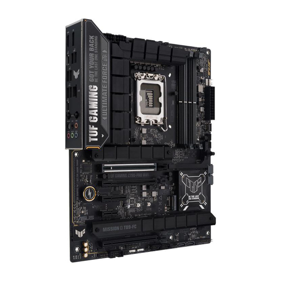
- Page 1 TUF GAMING Z790-PRO WIFI...
- Page 2 Product warranty or service will not be extended if: (1) the product is repaired, modified or altered, unless such repair, modification of alteration is authorized in writing by ASUS; or (2) the serial number of the product is defaced or missing.
-
Page 3: Table Of Contents
Contents Safety information ...................... iv About this guide ......................v TUF GAMING Z790-PRO WIFI specifications summary ........viii Package contents ...................... xii Chapter 1: Product Introduction Before you proceed ................... 1-1 Motherboard layout..................1-2 Motherboard rear and audio connections ..........1-23 1.3.1... -
Page 4: Safety Information
Safety information Electrical safety • To prevent electrical shock hazard, disconnect the power cable from the electrical outlet before relocating the system. • When adding or removing devices to or from the system, ensure that the power cables for the devices are unplugged before the signal cables are connected. If possible, disconnect all power cables from the existing system before you add a device. -
Page 5: About This Guide
Refer to the following sources for additional information and for product and software updates. ASUS website The ASUS website (www.asus.com) provides updated information on ASUS hardware and software products. Optional documentation Your product package may include optional documentation, such as warranty flyers, that may have been added by your dealer. - Page 6 Motherboard Installation Guide Please visit https://www.asus.com/support for more information on the Motherboard Installation Guide. Driver and Utilities FAQ Please visit https://www.asus.com/support for more information on downloading and installing drivers and utilities for your motherboard. RAID Configuration Guide Please visit https://www.asus.com/support for more information on the RAID...
- Page 7 Conventions used in this guide To ensure that you perform certain tasks properly, take note of the following symbols used throughout this user guide. CAUTION: Information to prevent damage to the components and injuries to yourself when trying to complete a task. IMPORTANT: Instructions that you MUST follow to complete a task.
-
Page 8: Tuf Gaming Z790-Pro Wifi Specifications Summary
Supports Intel Turbo Boost Technology 2.0 and Intel Turbo Boost Max ® ® Technology 3.0** * Refer to www.asus.com for CPU support list. ** Intel Turbo Boost Max Technology 3.0 support depends on the CPU types. ® Chipset Intel Z790 Chipset ®... - Page 9 TUF GAMING Z790-PRO WIFI specifications summary 1 x Intel 2.5Gb Ethernet ® Ethernet TUF LANGuard Wi-Fi 6E 2x2 Wi-Fi 6E (802.11ax) Supports 2.4/5/6GHz frequency band* Wireless & Bluetooth ® Bluetooth v5.3** ® * WiFi 6GHz regulatory may vary between countries.
- Page 10 TUF GAMING Z790-PRO WIFI specifications summary Fan and Cooling Related 1 x 4-pin CPU Fan header 1 x 4-pin CPU OPT Fan header 1 x 4-pin AIO Pump header 4 x 4-pin Chassis Fan headers Power Related 1 x 24-pin main power connector...
- Page 11 10 64-bit Operating System ® ® ATX Form Factor Form Factor 12 inch x 9.6 inch ( 30.5 cm x 24.4 cm ) Specifications are subject to change without notice. Please refer to the ASUS website for the latest specifications.
-
Page 12: Package Contents
Package contents Check your motherboard package for the following items. Motherboard 1 x TUF GAMING Z790-PRO WIFI motherboard Cables 2 x SATA 6Gb/s cables 1 x ASUS WiFi Q-Antenna 1 x TUF GAMING sticker Miscellaneous 2 x M.2 rubber packages 1 x Screw package for M.2 SSD... -
Page 13: Chapter 1: Product Introduction
Chapter 1: Product Introduction Product Introduction Before you proceed Take note of the following precautions before you install motherboard components or change any motherboard settings. • Unplug the power cord from the wall socket before touching any component. • Before handling components, use a grounded wrist strap or touch a safely grounded object or a metal object, such as the power supply case, to avoid damaging them due to static electricity. -
Page 14: Motherboard Layout
Motherboard layout 24.4cm(9.6in) CPU_OPT AIO_PUMP CPU_FAN CPU_12V_2 CPU_12V_1 HDMI_DP DIGI+ U10G_C9 U5G_E34 U5G_E12 LAN_U10G_34 LGA1700 U20G_C1 M.2(WIFI) AUDIO Intel Ethernet M.2_1(SOCKET3) PCIE SATA IRST 4.0 X4 2242 2260 2280 22110 PCIEX16(G5) PCIEX16(G3) Intel ® BATTERY M.2_2(SOCKET3) Z790 PCIE SATA IRST 4.0 X4 PCIEX4(G4) 2280... - Page 15 Layout contents Page 1. CPU socket 2. DIMM slots 3. Expansion slots 4. Fan and Pump headers 5. Power connectors 1-10 6. M.2 slots 1-11 7. SATA 6Gb/s ports 1-12 8. USB 20Gbps Type-C® Front Panel connector 1-13 9. USB 5Gbps header 1-13 10.
- Page 16 ® ® LGA1700 • Keep the cap after installing the motherboard. ASUS will process Return Merchandise Authorization (RMA) requests only if the motherboard comes with the cap on the CPU socket. • The product warranty does not cover damage to the socket contacts resulting from incorrect CPU installation/removal, or misplacement/loss/incorrect removal of the PnP cap.
- Page 17 (D/C) from the same vendor. Check with the vendor to get the correct memory modules. • Visit the ASUS website for the latest QVL. Motherboard User Manual...
- Page 18 Unplug the power cord before adding or removing expansion cards. Failure to do so may cause you physical injury and damage motherboard components. To install a PCIe expansion card, please refer to the Motherboard Installation Guide on the ASUS support site. PCIEX16(G5) PCIEX16(G3)
- Page 19 Additional PCIe bifurcation and M.2 settings for RAID function are also supported when a Hyper M.2 x16 series card is installed. • For full details on the PCIe bifurcation, you may visit the support site at https://www.asus.com/support/FAQ/1037507/. • The Hyper M.2 x16 series card is sold separately. •...
- Page 20 Using the PCIe Slot Q-Release PCIEX16(G5) slot comes with a PCIe Slot Q-Release button allowing you to easily remove an expansion card installed to this PCIe slot, even when the expansion card may be blocking the PCIe push-latch, such as a graphics card. To release an expansion card using the PCIe Slot Q-Release: Press the PCIe Slot Q-Release button with one hand whilst slightly lifting the expansion card with the other hand.
- Page 21 Fan and Pump headers The Fan and Pump headers allow you to connect fans or pumps to cool the system. CPU_FAN CPU_OPT CHA_FAN1 CHA_FAN2 CHA_FAN3 CHA_FAN4 AIO_PUMP • DO NOT forget to connect the fan cables to the fan headers. Insufficient air flow inside the system may damage the motherboard components.
- Page 22 Power connectors These Power connectors allow you to connect your motherboard to a power supply. The power supply plugs are designed to fit in only one orientation. Find the proper orientation and push down firmly until the power supply plugs are fully inserted. CPU_12V_1 ATX_PWR CPU_12V_2...
- Page 23 M.2 slots The M.2 slots allow you to install M.2 devices such as M.2 SSD modules. M.2_1 M.2_2 M.2_3 M.2_4 Intel Core™ Processors (14 & 13 & 12 Gen): • ® - M.2_1 slot (Key M), type 2242/2260/2280/22110 (supports PCIe 4.0 x4 mode) Intel Z790 Chipset: •...
- Page 24 Intel Rapid Storage Technology through the onboard Intel Z790 chipset. ® ® Before creating a RAID set, refer to the RAID Configuration Guide. You can download the RAID Configuration Guide from the ASUS website. Chapter 1: Product Introduction 1-12...
- Page 25 USB 20Gbps Type-C Front Panel connector ® The USB 20Gbps Type-C connector allows you to connect a USB 20Gbps Type-C ® ® module for additional USB 20Gbps ports on the front panel. The USB 20Gbps Type-C connector provides data transfer speeds of up to 20 Gb/s and PD 3.0 support ®...
- Page 26 10. USB 2.0 headers The USB 2.0 headers allow you to connect USB modules for additional USB 2.0 ports. The USB 2.0 headers provide data transfer speeds of up to 480 Mb/s. USB_1011 USB_1213 DO NOT connect a 1394 cable to the USB connectors. Doing so will damage the motherboard! The USB 2.0 module is purchased separately.
- Page 27 11. Addressable Gen2 headers The Addressable Gen2 headers allow you to connect individually addressable RGB WS2812B LED strips or WS2812B based LED strips. ADD GEN2_1 ADD GEN2_2 ADD GEN2_3 Before you install or remove any component, ensure that the power supply is switched off or the power cord is detached from the power supply.
- Page 28 12. Aura RGB header The Aura RGB header allows you to connect RGB LED strips. RGB_HEADER Before you install or remove any component, ensure that the power supply is switched off or the power cord is detached from the power supply. Failure to do so may cause severe damage to the motherboard, peripherals, or components.
- Page 29 13. Clear CMOS header The Clear CMOS header allows you to clear the Real Time Clock (RTC) RAM in the CMOS, which contains the date, time, system passwords, and system setup parameters. CLRTC To erase the RTC RAM: Turn OFF the computer and unplug the power cord. Short-circuit pin 1-2 with a metal object or jumper cap for about 5-10 seconds.
- Page 30 14. COM Port header The COM (Serial) Port header allows you to connect a COM port module. Connect the COM port module cable to this header, then install the module to a slot opening on the system chassis. The COM port module is purchased separately. Chapter 1: Product Introduction 1-18...
- Page 31 15. Front Panel Audio header The Front Panel Audio header is for a chassis-mounted front panel audio I/O module that supports HD Audio. Connect one end of the front panel audio I/O module cable to this header. F_AUDIO We recommend that you connect a high-definition front panel audio module to this connector to avail of the motherboard’s high-definition audio capability.
- Page 32 16. System Panel header The System Panel header supports several chassis-mounted functions. PANEL • System Power LED header (PLED) The 2-pin and/or 3-1 pin headers allow you to connect the System Power LED. The System Power LED lights up when the system is connected to a power source, or when you turn on the system power, and blinks when the system is in sleep mode.
- Page 33 17. Thunderbolt™ (USB4 ) header ® The Thunderbolt™ (USB4 ) header allows you to connect an add-on Thunderbolt™ ® I/O card that supports Intel®’s Thunderbolt™ Technology, allowing you to connect Thunderbolt™-enabled devices to form a daisy-chain configuration. TB_HEADER Please visit the official website of your purchased Thunderbolt™ card for more details on compatibility.
- Page 34 18. Q-LEDs The Q-LEDs check key components (CPU, DRAM, VGA, and booting devices) during the motherboard booting process. If an error is found, the critical component’s LED stays lit up until the problem is solved. CPU (RED) DRAM (YELLOW) VGA (WHITE) BOOT (YELLOW GREEN) •...
-
Page 35: Motherboard Rear And Audio Connections
Motherboard rear and audio connections 1.3.1 Rear I/O connection Rear panel connectors DisplayPort USB 5Gbps (Blue) Type-A ports E1, E2, E3, and E4 Intel 2.5Gb Ethernet port* ® HDMI™ port USB 10Gbps Type-C port C9 ® USB 10Gbps (Teal blue) Type-A ports 3 and 4 USB 20Gbps Type-C port C1 ®... - Page 36 * Intel 2.5Gb Ethernet port LED indications ® Activity Link LED Speed LED ACT/LINK SPEED Status Description Status Description No link No link 100 Mbps / 10 Mbps GREEN Linked connection LAN port BLINKING Data activity GREEN 2.5 Gbps connection ORANGE 1 Gbps connection ** Audio 2, 4, 5.1 or 7.1-channel configuration...
-
Page 37: Audio I/O Connections
1.3.2 Audio I/O connections Audio I/O ports Connect to Headphone and Mic Connect to 2-channel Speakers Connect to 4-channel Speakers Motherboard User Manual 1-25... - Page 38 Connect to 5.1-channel Speakers Connect to 7.1-channel Speakers Chapter 1: Product Introduction 1-26...
-
Page 39: Chapter 2: Basic Setup
Install a heatsink or AIO cooler after installing the CPU. Please refer to the Motherboard Installation Guide on the ASUS support site, or to the user manual of the heatsink/AIO cooler for steps on installing the heatsink/AIO cooler. Take caution when lifting the load... - Page 40 Ensure to remove the CPU Socket lever protector on the lever latch before locking the lever latch under the retention tab. Failure to do so may cause damages to your system when installing the cooling system. Chapter 2: Basic Installation...
-
Page 41: Dimm Installation
DIMM installation DIMM removal Motherboard User Manual... -
Page 42: M.2 Installation
M.2 installation • The illustrations only show the installation steps for a 22110 M.2 slot, the steps are the same for the other M.2 slots. • Use a Phillips screwdriver when removing or installing the screws or screw stands mentioned in this section. •... - Page 43 (optional) If required, remove the pre-installed removable M.2 Q-Latch screw at the 2280 length screw hole. Only follow this step if a removable M.2 Q-Latch screw is pre-installed at the 2280 length screw hole and can be removed. (optional) Install the bundled rubber for M.2 if you are installing a single sided M.2 module.
- Page 44 (optional) Install the M.2 Q-Latch to the M.2 length screw hole you wish to install your M.2 module to. You can use a bundled M.2 Q-Latch screw or a pre-installed removable M.2 Q-Latch screw. Rotate and adjust the M.2 Q-Latch so that the handle points away from the M.2 slot. Install your M.2 module to the M.2 slot.
- Page 45 Replace the heatsinks. Secure the heatsinks using the screws on the heatsinks. Motherboard User Manual...
-
Page 46: Motherboard Installation
Motherboard installation (on selected models) Install the bundled I/O Shield to the chassis rear I/O panel. Only install the I/O Shield if your motherboard does not have a pre-installed I/O shield. Place the motherboard into the chassis, ensuring that its rear I/O ports are aligned to the chassis’... -
Page 47: Expansion Card Installation
Expansion card installation 2.5.1 Thunderbolt™ series card installation 6-pin PCIe power connector USB Type-C ® port connects to Thunderbolt devices MiniDP in port connects to DP out port on the motherboard or a VGA card USB 2.0 header Thunderbolt™ header The Thunderbolt™... -
Page 48: Asus Wifi Q-Antenna Installation (On Selected Models)
Using ASUS WiFi Q-Antenna functions The ASUS WiFi Q-Antenna features a Direction Finder and Fast Check function, you can learn more about these feature and how to use them in the ASUS WiFi Q-Antenna tab in Armoury Crate. The ASUS WiFi Q-Antenna function in Armoury Crate is only supported on the bundled antenna and Wi-Fi module. -
Page 49: Starting Up For The First Time
Starting up for the first time After making all the connections, replace the system case cover. Ensure that all switches are off. Connect the power cord to the power connector at the back of the system chassis. Connect the power cord to a power outlet that is equipped with a surge protector. Turn on the devices in the following order: Monitor External storage devices (starting with the last device on the chain) - Page 50 Chapter 2: Basic Installation 2-12...
-
Page 51: Chapter 3: Bios And Raid Support
For more details on BIOS and RAID configurations, please refer to Manual & Document under the Support tab of the product information site, or visit https://www.asus.com/support. Knowing UEFI BIOS BIOS (Basic Input and Output System) stores system hardware settings such as storage device configuration, overclocking settings, advanced power management, and boot device configuration that are needed for system startup in the motherboard CMOS. -
Page 52: Asus Ez Flash 3
ASUS EZ Flash 3 The ASUS EZ Flash 3 feature allows you to update the BIOS without using an OS-based utility. Ensure to load the BIOS default settings to ensure system compatibility and stability. Select the Load Optimized Defaults item under the Exit menu or press the <F5> hotkey. -
Page 53: Asus Crashfree Bios 3
ASUS CrashFree BIOS 3 The ASUS CrashFree BIOS 3 utility is an auto recovery tool that allows you to restore the BIOS file when it fails or gets corrupted during the updating process. You can restore a corrupted BIOS file using a USB flash drive that contains the BIOS file. -
Page 54: Raid Configurations
RAID configurations The motherboard supports RAID configurations. RAID definitions RAID 0 (Data striping) optimizes two identical hard disk drives to read and write data in parallel, interleaved stacks. Two hard disks perform the same work as a single drive but at a sustained data transfer rate, double that of a single disk alone, thus improving data access and storage. -
Page 55: Appendix
Appendix General Notices FCC Compliance Information Responsible Party: Asus Computer International Address: 48720 Kato Rd., Fremont, CA 94538, USA Phone / Fax No: (510)739-3777 / (510)608-4555 This device complies with part 15 of the FCC Rules. Operation is subject to the following two conditions: (1) This device may not cause harmful interference, and (2) this device must accept any interference received, including interference that may cause undesired operation. - Page 56 ASUS products sold in Vietnam, on or after September 23, 2011,meet the requirements of the Vietnam Circular 30/2011/TT-BCT. Các sản phẩm ASUS bán tại Việt Nam, vào ngày 23 tháng 9 năm2011 trở về sau, đều phải đáp ứng các yêu cầu của Thông tư 30/2011/TT-BCT của Việt Nam.
- Page 57 AEEE Yönetmeliğine Uygundur ASUS Recycling/Takeback Services ASUS recycling and takeback programs come from our commitment to the highest standards for protecting our environment. We believe in providing solutions for you to be able to responsibly recycle our products, batteries, other components as well as the packaging materials.
-
Page 58: Notices For Wi-Fi Model
Notices for Wi-Fi model FCC RF Caution Statement WARNING: Any changes or modifications not expressly approved by the party responsible for compliance could void your authority to operate the equipment. FCC Wi-Fi 6E Caution Statement Operation of transmitters in the 5.925-7.125 GHz band is prohibited for control of or communications with unmanned aircraft systems. - Page 59 KC: Korea Warning Statement NCC: Wireless Statement 取得審驗證明之低功率射頻器材,非經核准,公司、商號或使用者均不 得擅自變更頻率、加大功率或變更原設計之特性及功能。低功率射頻器 材之使用不得影響飛航安全及干擾合法通信;經發現有干擾現象時,應 立即停用,並改善至無干擾時方得繼續使用。前述合法通信,指依電信 管理法規定作業之無線電通信。低功率射頻器材須忍受合法通信或工 業、科學及醫療用電波輻射性電機設備之干擾。 應避免影響附近雷達系統之操作。 Japan RF Equipment Statement 屋外での使用について 電波法の定めにより5.2GHz、 5.3GHz、 及び6GHz帯域の電波は屋外での使用が禁じられています (法令により許可された場合を除く) 。 法律および規制遵守 本製品は電波法及びこれに基づく命令の定めるところに従い使用してください。 日本国外では、 その国の法律または規制により、 本製品の使用ができないことがあります。 このような国では、 本 製品を運用した結果、 罰せられることがありますが、 当社は一切責任を負いかねますのでご了承 ください。 Précautions d’emploi de l’appareil : Soyez particulièrement vigilant quant à...
- Page 60 ASUSTek Computer Inc. hereby declares that this device is in compliance with the essential requirements and other relevant provisions of The Radio Equipment Regulations 2017 (S.I. 2017/1206). Full text of UKCA declaration of conformity is available at https://www.asus.com/support/. The WiFi operating in the band 5150-5350MHz shall be restricted to indoor use for the country listed below:...
- Page 61 постановления на свързаната Директива 2014/53/EC. Пълният текст на ЕС der Richtlinie 2014/53/EU übereinstimmt. Der gesamte Text der EU- декларация за съвместимост е достъпен на адрес Konformitätserklärung ist verfügbar unter: https://www.asus.com/support/. https://www.asus.com/support/. Der WLAN-Betrieb im Band von 5150-5350 MHz ist für die in der unteren WiFi, работеща...
- Page 62 Käesolevaga kinnitab ASUSTek Computer Inc, et seade vastab direktiivi zahtjevima i ostalim odgovarajućim odredbama direktive 2014/53/EU. Cijeli 2014/53/EÜ olulistele nõuetele ja teistele asjakohastele sätetele. EL tekst EU izjave o sukladnosti dostupan je na https://www.asus.com/support/. vastavusdeklaratsiooni täistekst on saadaval veebisaidil https://www.asus.com/support/.
- Page 63 Az EU megfelelőségi nyilatkozat teljes szövegét a ASUSTek Computer Inc. erklærer herved at denne enheten er i samsvar med következő weboldalon tekintheti meg: https://www.asus.com/support/. hovedsaklige krav og andre relevante forskrifter i direktivet 2014/53/EU. Az 5150-5350 MHz-es sávban működő Wi-Fi-t beltéri használatra kell Fullstendig tekst for EU-samsvarserklæringen finnes på:...
- Page 64 Direktive 2014/53/EU. Polno 5150-5350 MHz arasındaki WiFi çalışması, tabloda listelenen ülkeler için iç besedilo izjave EU o skladnosti je na voljo na https://www.asus.com/support/. mekân kullanımıyla kısıtlanacaktır. WiFi, ki deluje v pasovnem območju 5150–5350 MHz, mora biti v državah, Düşük Güç...
- Page 65 ASUSTek Computer Inc. заявляє, що цей пристрій відповідає основним вимогам та іншим відповідним вимогам Директиви 2014 / 53 / EU. Повний текст декларації відповідності нормам ЄС доступний на https://www.asus.com/support/. Робота Wi-Fi на частоті 5150-5350 МГц обмежується використанням у приміщенні для країн, поданих у таблиці нижче: Пристрої...
-
Page 66: Warranty
• ASUS offers a voluntary manufacturer’s Commercial Guarantee. • ASUS dragovoljno nudi komercijalno proizvođačko jamstvo. • ASUS reserves the right to interpret the provisions of the ASUS • ASUS zadržava prava na tumačenje odredbi ASUS komercijalnog Commercial Guarantee. jamstva. •... - Page 67 ASUS forbeholder seg retten til å tolke bestemmelsene i ASUS sin • Bảo hành thương mại này của ASUS được cung cấp độc lập và ngoài kommersielle garanti. Bảo đảm pháp lý theo luật định và không có cách nào ảnh hưởng đến hoặc giới hạn các quyền theo Bảo lãnh pháp lý.
-
Page 68: Asus Contact Information
Address: 1F., No. 15, Lide Rd., Beitou Dist., Taipei City 112 ASUS COMPUTER INTERNATIONAL (America) Address: 48720 Kato Rd., Fremont, CA 94538, USA ASUS COMPUTER GmbH (Germany and Austria) Address: Harkortstrasse 21-23, 40880 Ratingen, Germany ASUSTeK (UK) LIMITED Address: 1st Floor, Sackville House, 143-149 Fenchurch Street, London, EC3M 6BL,...
Need help?
Do you have a question about the TUF GAMING Z790-PRO WIFI and is the answer not in the manual?
Questions and answers