
Related Manuals for DeLonghi DVRS 916-DF Series


Summary of Contents for DeLonghi DVRS 916-DF Series
- Page 1 DE ’ L O N G H I C OO KING INSTALLATION & USER INSTRUCTIONS D VRS 9 16 -D F/ . . DUAL FUEL COOKER...
-
Page 2: Table Of Contents
CONTENTS Page Number Introduction.................... 3 Important Safeguards & Recommendations......... 4-10 Advice for the installer............... 11 Installation....................12-16 Gas installation..................17-22 Electrical section..................23-24 Advice for the user................26 Cooking Hob................... 27 Control Panel..................28 Use of the Hob Burners................ 29-31 Gas Oven.................... -
Page 3: Introduction
Dear Customer, Thank you for purchasing the DeLonghi DVRS 916-DF/.. dual fuel cooker. The safety precautions and recommendations listed below are for your own safety and that of others. They will also provide a means by which to make full use of the features offered by your appliance. -
Page 4: Important Safeguards & Recommendations
IMPORTANT SAFETY PRECAUTIONS AND RECOMMENDATIONS IMPORTANT: This appliance is designed and manufactured solely for the cooking of domestic (household) food and is not suitable for any non domestic application and therefore should not be used in a commercial environment. The appliance guarantee will be void if the appliance is used within a non domestic environment i.e. - Page 5 • Do not attempt to modify the technical characteristics of the appliance as this may become dangerous to use. The manufacturer declines all responsibility for any inconvenience resulting from the inobservance of this condition. • CAUTION: this appIiance must only be installed in a permanently ventilated room in compliance with the applicable regulations.
- Page 6 • The manufacturer declines all liability for injury to persons or damage to property caused by incorrect or improper use of the appliance. • WARNING: During use the appliance and its accessible parts become hot; they remain hot for some time after use. Care should be taken to avoid touching heating elements (on –...
- Page 7 • Do not line the oven walls or base with aluminium foil. Do not place baking trays or the drip tray on the base of the oven chamber. • FIRE RISK! Do not store flammable material in the oven. • Always use oven gloves when removing the shelves and food trays from the oven whilst hot.
- Page 8 Children less than 8 years of age shall be kept away unless continuously supervised. • WARNING: Use only hob guards designed by the manufacturer of the cooking appliance or indicated by the manufacturer of the appliance in the instructions for use as suitable or hob guards incorporated in the appliance.
- Page 9 ENERGY LABELLING/ECODESIGN • Commission delegated regulation (EU) No 65/2014 (supplementing Directive 2010/30/EU of the European Parliament and of the Council). • Commission regulation (EU) No 66/2014 (implementing Directive 2009/125/EC of the European Parliament and of the Council). Reference to the measurement and calculation methods used to establish compliance with the above requirements: •...
- Page 10 WARNING – VERY IMPORTANT ! FIRE/OVERHEATING HAZARD: • Do not place towels/cloths etc onto the hob rail or oven door handle/s whilst the product is in use or hot. TO AVOID DAMAGE TO THE APPLIANCE: • Do not lift/move the cooker by the hob rail or oven door handle/s. •...
-
Page 11: Advice For The Installer
Advice for the installer IMPORTANT • The appliance is designed and approved for domestic use only and should not be installed in a commercial, semi commercial or communal environment. Your product will not be guaranteed if installed in any of the above environments and could affect any third party or public liability insurances you may have. -
Page 12: Installation
1 - INSTALLATION This cooker has class “2/1” overheating protection so that it can be installed next to a cabinet. If the cooker is installed adjacent to furniture which is higher than the gas hob cooktop, a gap of at least 200 mm must be left between the side of the cooker and the furniture. The walls and kitchen furniture surrounding the appliance must be made of non-flammable material. - Page 13 FITTING THE ADJUSTABLE FEET The adjustable feet must be fitted to the base of the cooker before use (fig. 1.2). Rest the rear of the cooker on a piece of the polystyrene packaging exposing the base for the fitting of the feet. Fit the 4 legs by screwing them tight into the support base as shown in figure 1.3.
- Page 14 MOVING THE COOKER WARNING: When raising cooker to upright position always ensure two people carry out this manoeuvre to prevent damage to the adjustable feet (fig. 1.6). Fig. 1.6 WARNING WARNING When moving cooker to its final position Be carefull: do not lift the cooker by the DO NOT DRAG (fig.
- Page 15 ANTI-TILT BRACKET Important! To restrain the appliance and prevent it tipping accidentally, fit the supplied bracket to the rear wall to fix it securely. To fit the anti-tilt bracket: After you have located where the cooker is to be positioned, mark on the wall the place where the two screws of the anti-tilt bracket have to be fitted.
- Page 16 PROVISION FOR VENTILATION • The appliance should be installed into a room or space with an air supply in accordance with the current version of BS 5440-2: 2000. • For rooms with a volume of less than 5m - permanent ventilation of 100 cm free area must be provided.
-
Page 17: Gas Installation
2 - GAS INSTALLATION IMPORTANT NOTE This appliance is supplied for use on NATURAL GAS or LPG (check the gas regulation label attached on the appliance). • Appliances supplied for use on NATURAL GAS are adjusted for this gas only and cannot be used on any other gas (LPG) without modification. - Page 18 RESTRAINING CHAIN Fig. 2.1 Chain security holes Cooker Back of the cooker Rear wall Installation to Natural Gas Installation to Natural Gas must conform to the Code of Practice, etc. The supply pressure for Natural Gas is 20 mbar. The installation must conform to the relevant British/European Standards. Installation to LP Gas When operating on Butane gas a supply pressure of 28-30 mbar is required.
- Page 19 Notes: • Flexible hoses can be used where the sited ambient temperature of the hose does not exceed 70°C. These hoses must be manufactured in accordance with BS669 part 1 or EN 14800 and be of the correct construction for the type of gas being used.
- Page 20 Fitting the plug Fig. 2.3 on the inlet pipe terminal not used Cooker manifold (right Cooker or left inlet pipe) manifold (right or left inlet pipe) Manifold male Manifold pipe fitting male 1/2” G cylindrical pipe fitting (ISO 228-1) male 1/2”...
- Page 21 CONVERSION TO NATURAL GAS OR TO LPG CONVERSION TO NATURAL GAS OR TO LPG REPLACEMENT OF THE INJECTORS Auxiliary, If the injectors are not supplied they can Semi-rapid and be obtained from the After-Sales Service. Rapid burners Select the injectors to be replaced according to the “Table for the choice of the injectors”.
- Page 22 TABLE FOR THE CHOICE OF THE INJECTORS Cat: 2H3+ Natural Gas G30 28-30 mbar Nominal Reduced G20 20 mbar G31 37 mbar BURNERS Power Power [Hs - kW] [Hs - kW] Ø injector Ø injector [1/100 mm] [1/100mm] Auxiliary (A) 1,00 0,40 72 (X)
-
Page 23: Electrical Section
3 - ELECTRICAL INSTALLATION IMPORTANT: The appliance must be installed in accordance with the manufacturer’s instructions. Incorrect installation, for which the manufacturer accepts no responsibility, may cause damage to persons, animals and property. The connection of the appliance to earth is mandatory. The manufacturer declines all responsibility for any inconvenience resulting from the inobservance of this condition. - Page 24 CONNECTION OF THE POWER SUPPLY CABLE WARNING: If the power supply cable is damaged, it must be replaced only by an authorised service agent in order to avoid a hazard. • Unhook the terminal board cover by inserting a screwdriver into the two hooks “A” (fig. 3.1).
-
Page 26: Advice For The User
Advice for the users... -
Page 27: Cooking Hob
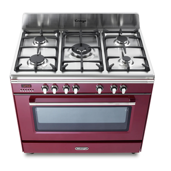
1 - COOKING HOB Fig. 1.1 GAS BURNERS Auxiliary burner (A) 1,00 kW Semi-rapid burner (SR) 1,75 kW Rapid burner (R) 3,00 kW Double-ring compact burner (DCC) 4,00 kW Notes: • The electric ignition is incorporated in the knobs. • The appliance has a safety valve system fitted, the flow of gas will be stopped if and when the flame should accidentally go out. -
Page 28: Control Panel
2 - CONTROL PANEL Fig. 2.1 CONTROLS DESCRIPTION Front right burner control knob Rear right burner control knob Central burner control knob Rear left burner control knob Front left burner control knob Multifunction oven thermostat control knob Multifunction oven function selector control knob Electronic programmer Pilot lamp: Oven temperature indicator light... -
Page 29: Use Of The Hob Burners
3 - USE OF THE HOB BURNERS GAS BURNERS Gas flow to the burners is adjusted by turning the knobs (illustrated in fig. 3.1) which control the safety valves. Make the symbol of the knob match with the indicator on the control panel to obtain: - symbol closed valve maximum... - Page 30 LIGHTING THE BURNERS CHOICE OF THE BURNER ignite burner, following On the control panel, near every knob instructions are to be followed: there is a diagram that indicates which burner is controlled by that knob. Press in the corresponding knob and The suitable burner must be chosen turn counter-clockwise (fig.
- Page 31 CORRECT USE OF THE DOUBLE-RING COMPACT BURNER Only flat bottom pans of the correct size are to be placed on the pan support above the Double-ring compact burner. When using a WOK, the supplied wok stand must be placed onto the pan stand to avoid any faulty operation of the triple-ring burner (fig.
-
Page 32: Gas Oven
4 - MULTIFUNCTION ELECTRIC OVEN OPERATING PRINCIPLES Attention: The oven door becomes Heating cooking very hot during operation. MULTIFUNCTION oven are obtained in the Keep children away. following ways: by normal convection GENERAL FEATURES The heat is produced by the upper and As its name indicates, this is an oven lower heating elements. - Page 33 Fig. 4.1 Fig. 4.2 TEMPERATURE KNOB (fig. 4.2) To turn on the heating elements of the oven, set first the function selector to the required setting and then the thermostat knob to the desired temperature. To set the temperature, line up the temperature knob indicator with the required temperature.
- Page 34 UPPER HEATING ELEMENT In this position only the upper element is switched on. Heat is distributed by natural convection. The temperature must be regulated between 50°C and the maximum position with the thermostat knob. Recommended for: To complete cooking of dishes that require higher temperature at the top. GRILLING The infra-red heating element is switched on.
- Page 35 HOT AIR COOKING The circular element and the fan are on. The heat is diffused by forced convection and the temperature must be regulated between 50°C and 250 °C with the thermostat knob. It is not necessary to preheat the oven. Cooking temperature may be reduced for fan assisted ovens, see “OVEN TEMPERATURE GUIDE”.
-
Page 36: Oven Temperature Guide
5 - OVEN TEMPERATURE GUIDE Electric oven temperature Cooking process Oven heat Gas mark °C °F Keeping food hot, very cool ½ milk puddings Egg custards cool Rich fruit cakes, cool braising Low temperature moderate roasting, shortbread Victoria sandwich, plain fruit cake, moderate baked fish Small cakes, choux... -
Page 37: Electronic Programmer
6 - ELECTRONIC PROGRAMMER The electronic programmer is a device which groups together the following functions: • 24 hours clock with illuminated display • Timer (up to 23 hours and 59 minutes) • Program for automatic oven cooking • Program for semi-automatic oven cooking Description of the buttons: Description illuminated... - Page 38 ELECTRONIC CLOCK ELECTRONIC TIMER (fig. 6.2) The programmer is equipped with an The timer program consists only of a electronic clock with illuminated numbers buzzer which may be set for a maximum which indicates hours and minutes. period of 23 hours and 59 minutes. Upon immediate connection of the oven or If the AUTO symbol is flashing push the after a power cut, three zeros will flash on...
- Page 39 AUTOMATIC OVEN COOKING Set the temperature and the cooking program by using the switch and To cook food automatically in the oven, it is thermostat knobs of the oven (see necessary to: specific chapters). Set the length of the cooking period. oven programmed Set the end of the cooking time.
- Page 40 SEMI-AUTOMATIC COOKING At the end of the cooking time the oven will turn off automatically, the symbol This is used to automatically switch off the will turn off, AUTO will flash and a buzzer oven after the desired cooking time has will be sound, which can be turned off by elapsed.
- Page 41 IMPORTANT – MAIN OVEN NOT WORKING If the main Oven is not working, it may have been accidently set to “AUTOMATIC” or the power to the appliance was interrupted. If the Timer is showing the letter “AUTO” as below or the time of day is flashing, the Oven may not turn on or be delayed in its operation. Before requesting a service call, please refer to the timer set up instructions in this handbook and ensure the timer is set to “MANUAL”...
-
Page 42: Cleaning And Maintenance
7 - CLEANING AND MAINTENANCE GENERAL ADVICE CLEANING • Before you begin cleaning, you • Stainless steel hob: Spillage on must ensure that the appliance is the hob can usually be removed by switched off at the cooker switch. a damp soapy cloth. More obstinate stains can be removed by using a •... - Page 43 BURNERS AND PAN SUPPORTS • Inside of oven: The oven should always be cleaned after use when it These parts must be cleaned using a has cooled down. The cavity should be sponge and soapy water or other suitable cleaned using a mild detergent solution non-abrasive products.
- Page 44 Fig. 7.1 Fig. 7.2 Fig. 7.3 Fig. 7.4 Fig. 7.5...
- Page 45 OVEN FITTING OUT • Assemble the wire racks to the oven walls using the 2 screws (fig. 7.6). • Slide the rack into the runners (fig. 7.7). The rack must be fitted so that the safety notch, which stops it sliding out, faces the inside of the oven;...
- Page 46 REPLACING THE OVEN LAMPS WARNING: Ensure the appliance is switched off before replacing the lamp to avoid the possibility of electric shock. • Let the oven cavity and the heating elements to cool down; • Switch off the electrical supply; •...
- Page 47 GREASE FILTER A special screen is provided at the back of the oven to catch grease particles, mainly when meat is being roasted (fig. 7.9). • When baking pastry etc. this filter should be removed. • Slide in the grease filter on the back of the oven as in fig. 7.9. Clean the filter after any cooking! •...
- Page 48 TELESCOPIC SLIDING SHELF SUPPORTS The telescopic sliding shelf supports make it safer and easier to insert and remove the oven shelves and trays. They stop when they are pulled out to the maximum position. Important! When fitting the sliding shelf supports, make sure that you fit: •...
- Page 49 To remove the telescopic sliding shelf supports: • Remove the side racks by unscrewing the fixing screws (fig. 7.12). • Lay down the telescopic sliding shelf support and side racks, with the telescopic sliding shelf support underneath. • Find the safety locks. These are the tabs that clip over the wire of the side rack (arrow 1 in fig.
- Page 50 REMOVING THE OVEN DOOR The oven door can easily be removed as follows: • Open the door to the full extent (fig. 7.14). • Open the lever “A” completely on the left and right hinges (fig. 7.15). • Hold the door as shown in fig. 7.17. •...
- Page 51 REFIT THE DOOR Hold the door firmly (fig. 7.20). Insert the hinge tongues into the slots, making sure that the groove drops into place as shown in the figure 7.20. Open the door to its full extent. Fully close the levers “A” on the left and right hinges, as shown in the figure 7.21. Close the door and check that it is properly in place.
-
Page 52: Guarantee & After Sales Service
8 - GUARANTEE Your new “De’Longhi” product comes with 12-month guarantee covering all parts and labour. If your appliance proves to be defective as a result of faulty materials or workmanship during the guarantee period, these parts will be repaired or replaced free of charge. AFTER SALES SERVICE IMPORTANT –... - Page 56 De scri pt io n s a n d il lu st ra tio ns in th is b o ok let ar e g iv en a s simply indicati ve. Th e m an u fa ctu rer re se rv es th e r igh t,...
Need help?
Do you have a question about the DVRS 916-DF Series and is the answer not in the manual?
Questions and answers