
Related Manuals for xFusion Digital Technologies FusionServer 2288H V7


Summary of Contents for xFusion Digital Technologies FusionServer 2288H V7
- Page 1 FusionServer 2288H V7 Server Technical White Paper Issue Date 2023-05-25 xFusion Digital Technologies Co., Ltd.
- Page 2 Notice In this document, "xFusion" is used to refer to "xFusion Digital Technologies Co., Ltd." for concise description and easy understanding, which does not mean that "xFusion" may have any other meaning. Any "xFusion" mentioned or described hereof may not be understood as any meaning other than "xFusion Digital Technologies Co., Ltd.", and xFusion Digital Technologies Co., Ltd.
-
Page 3: About This Document
About This Document Purpose This document describes the appearance, features, performance parameters, and hardware and software compatibility of FusionServer 2288H V7, so that users can have an in-depth and detailed understanding of FusionServer 2288H V7. Intended Audience This document is intended for pre-sales engineers. - Page 4 FusionServer 2288H V7 Server Technical White Paper About This Document Change History Issue Release Date Change Description 2021-06-21 This issue is the first official release. Issue 02 (2023-05-25) Copyright © xFusion Digital Technologies Co., Ltd.
-
Page 5: Table Of Contents
5.5.1.3 12 x 3.5" Drive Pass-Through Configurations..................43 5.5.1.4 12 x 3.5" Drive EXP Configurations..................... 53 5.5.1.5 24 x 2.5" Drive Pass-Through Configurations..................58 5.5.1.6 24 x 2.5" Drive NVMe Configurations....................61 Issue 02 (2023-05-25) Copyright © xFusion Digital Technologies Co., Ltd. - Page 6 A.1.1.3 Quick Access Label...........................131 A.1.2 Chassis Internal Label..........................132 A.1.3 Chassis Tail Label..........................132 A.2 Product SN.............................. 133 A.3 Operating Temperature Limitations......................135 A.4 Nameplate............................... 149 A.5 RAS Features............................149 A.6 Sensor List...............................150 Issue 02 (2023-05-25) Copyright © xFusion Digital Technologies Co., Ltd.
- Page 7 B.1 A-E................................157 B.2 F-J................................158 B.3 K-O................................158 B.4 P-T................................158 B.5 U-Z................................159 C Acronyms and Abbreviations..................160 C.1 A-E................................160 C.2 F-J................................161 C.3 K-O................................162 C.4 P-T................................163 C.5 U-Z................................165 Issue 02 (2023-05-25) Copyright © xFusion Digital Technologies Co., Ltd.
-
Page 8: Overview
Technical White Paper 1 Overview Overview FusionServer 2288H V7 (2288H V7) is a new-generation 2U 2-socket rack server designed for the Internet, Internet Data Center (IDC), cloud computing, enterprise business, and telecom. The 2288H V7 server is ideal for IT core services, cloud computing, virtualization, high-performance computing, distributed storage, big data processing, enterprise or telecom applications, and other complex workloads. -
Page 9: Features
RAID 0, 1, 1E, 10, 5, 50, 6, and 60, depending on the RAID controller card used. It also uses a supercapacitor to protect the RAID cache data against power failures. Issue 02 (2023-05-25) Copyright © xFusion Digital Technologies Co., Ltd. - Page 10 ® ● Intel Software Guard Extensions (SGX) technology allows applications to run in their own independent space without being affected by other software running in the system, thereby enhancing security. Issue 02 (2023-05-25) Copyright © xFusion Digital Technologies Co., Ltd.
- Page 11 The improved thermal design with energy-efficient fans ensures optimal heat dissipation and reduces system power consumption. ● The server is protected with power capping and power control measures. ● Staggered spinup of drives reduces the server boot power consumption. Issue 02 (2023-05-25) Copyright © xFusion Digital Technologies Co., Ltd.
-
Page 12: Physical Structure
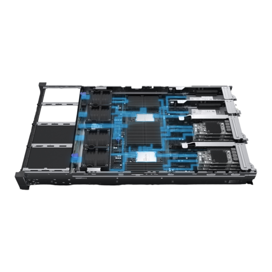
Intrusion sensor NOTE The air duct cannot be installed on a server configured with built-in drives or built-in cards. Front-drive backplane Left mounting ear plate Front drives Right mounting ear plate Issue 02 (2023-05-25) Copyright © xFusion Digital Technologies Co., Ltd. - Page 13 FusionServer 2288H V7 Server Technical White Paper 3 Physical Structure Fan modules Fan module brackets Fan board Processor heat sink Processor Cable organizer Mainboard Memory modules TPM/TCM OCP 3.0 NIC BMC card Issue 02 (2023-05-25) Copyright © xFusion Digital Technologies Co., Ltd.
-
Page 14: Logical Structure
● The BMC management chip integrated on the mainboard supports ports such as a video graphic array (VGA) port, a management network port, and a serial port. Issue 02 (2023-05-25) Copyright © xFusion Digital Technologies Co., Ltd. -
Page 15: Hardware Description
5.5 Storage 5.6 Network 5.7 I/O Expansion 5.8 PSUs 5.9 Fan Modules 5.10 LCD 5.11 Boards 5.1 Front Panel 5.1.1 Appearance ● 8 x 2.5" drive configuration Figure 5-1 Front view Issue 02 (2023-05-25) Copyright © xFusion Digital Technologies Co., Ltd. - Page 16 SN label) ● 12 x 3.5" drive configuration Figure 5-3 Front view Drive Slide-out label plate (with an SN label) ● 24 x 2.5" drive configuration: Figure 5-4 Front view Issue 02 (2023-05-25) Copyright © xFusion Digital Technologies Co., Ltd.
-
Page 17: Indicators And Buttons
Fault diagnosis LED FlexIO card 1 presence FlexIO card 2 presence indicator indicator iBMC direct connect management port indicator ● 12 x 2.5" drive configuration (4 x SAS/SATA + 8 x NVMe) Issue 02 (2023-05-25) Copyright © xFusion Digital Technologies Co., Ltd. - Page 18 Health status indicator Power button/indicator Fault diagnosis LED FlexIO card 1 presence FlexIO card 2 presence indicator indicator iBMC direct connect management port indicator ● 24 x 2.5" drive configuration: Issue 02 (2023-05-25) Copyright © xFusion Digital Technologies Co., Ltd.
- Page 19 Figure 5-10 Indicators and buttons on the front panel UID button/indicator Health status indicator Power button/indicator Fault diagnosis LED FlexIO card 1 presence FlexIO card 2 presence indicator indicator iBMC direct connect management port indicator Issue 02 (2023-05-25) Copyright © xFusion Digital Technologies Co., Ltd.
- Page 20 ● Blinking green at 2 Hz: The FlexIO card is detected and has just been inserted. ● Steady green: The FlexIO card is detected and the power supply is normal. Issue 02 (2023-05-25) Copyright © xFusion Digital Technologies Co., Ltd.
- Page 21 ● You can press this button to turn on or off the UID indicator. ● You can press and hold down this button for 4 to 6 seconds to reset the iBMC. Issue 02 (2023-05-25) Copyright © xFusion Digital Technologies Co., Ltd.
-
Page 22: Ports
Figure 5-11 Ports on the front panel USB 3.0 port iBMC direct connect management port VGA port ● 12 x 2.5" drive configuration (4 x SAS/SATA + 8 x NVMe) Issue 02 (2023-05-25) Copyright © xFusion Digital Technologies Co., Ltd. - Page 23 VGA port ● 24 x 2.5" drive configuration Figure 5-14 Ports on the front panel USB 3.0 port iBMC direct connect management port VGA port ● 25 x 2.5" drive configuration Issue 02 (2023-05-25) Copyright © xFusion Digital Technologies Co., Ltd.
- Page 24 ● For details about how to connect a USB device to the iBMC direct connect management port, see the FusionServer Rack Server iBMC User Guide. Issue 02 (2023-05-25) Copyright © xFusion Digital Technologies Co., Ltd.
-
Page 25: Rear Panel
Figure 5-16 Rear view I/O module 1 I/O module 2 I/O module 3 PSU 2 PSU 1 (Optional) FlexIO card 2 NOTE The FlexIO card slots support only OCP 3.0 NICs. Issue 02 (2023-05-25) Copyright © xFusion Digital Technologies Co., Ltd. - Page 26 OCP 3.0 NICs. NO TE ● For details about the OCP 3.0 NIC, see 5.6.1 OCP 3.0 NIC. ● The figure is for reference only. The actual configuration may vary. Issue 02 (2023-05-25) Copyright © xFusion Digital Technologies Co., Ltd.
-
Page 27: Indicators And Buttons
Figure 5-19 Indicators on the rear panel Data transmission status Connection status indicator for the indicator for the management network management network port port Serial port indicator UID indicator NOTE Reserved and unavailable currently Issue 02 (2023-05-25) Copyright © xFusion Digital Technologies Co., Ltd. - Page 28 The possible causes of no output are as follows: ● Power supply overtemperature protection ● Power output overcurrent or short- circuit ● Output overvoltage ● Short-circuit protection ● Device failure (excluding failure of all devices) Issue 02 (2023-05-25) Copyright © xFusion Digital Technologies Co., Ltd.
-
Page 29: Ports
Figure 5-20 Ports on the rear panel Management network Serial port port VGA port USB 3.0 port Socket for PSU 1 Socket for PSU 2 ● 4-GPU model Figure 5-21 Ports on the rear panel Issue 02 (2023-05-25) Copyright © xFusion Digital Technologies Co., Ltd. - Page 30 However, the USB 3.0 port must comply with the USB specifications. To run advanced peripherals, such as external CD/DVD drives, an external power supply is required. Issue 02 (2023-05-25) Copyright © xFusion Digital Technologies Co., Ltd.
-
Page 31: Processors
● For details about the optional components, consult the local sales representative or see "OS and Parts Compatibility" in the Compatibility Checker. Figure 5-22 Positions of the processors 5.4 Memory Issue 02 (2023-05-25) Copyright © xFusion Digital Technologies Co., Ltd. -
Page 32: Ddr5 Memory
Maximum memory speed ● 4800 MT/s Memory latency parameters ● A = 34-34-34 (CL-nRCD-nRP) ● B = 40-40-40 ● C = 42-42-42 DIMM type ● RD0: reference design for version RDIMM D0 Issue 02 (2023-05-25) Copyright © xFusion Digital Technologies Co., Ltd. -
Page 33: Memory Subsystem Architecture
A (primary) DIMM000(A) DIMM001(I) B (primary) DIMM010(B) DIMM011(J) C (primary) DIMM020(C) DIMM021(K) D (primary) DIMM030(D) DIMM031(L) E (primary) DIMM040(E) DIMM041(M) F (primary) DIMM050(F) DIMM051(N) G (primary) DIMM060(G) DIMM061(O) H (primary) DIMM070(H) Issue 02 (2023-05-25) Copyright © xFusion Digital Technologies Co., Ltd. -
Page 34: Memory Compatibility
® ® ● The memory module can be used with the new-generation Intel Xeon Scalable processors (Sapphire Rapids). The maximum memory capacity supported by all processor models is the same. Issue 02 (2023-05-25) Copyright © xFusion Digital Technologies Co., Ltd. -
Page 35: Dimm Installation Rules
● The memory modules configured must be DDR5 RDIMMs. ● The memory modules must be configured with the same number of ranks. ● Install filler memory modules in vacant slots. Issue 02 (2023-05-25) Copyright © xFusion Digital Technologies Co., Ltd. -
Page 36: Memory Installation Positions
The server supports up to 32 DDR5 memory modules. Observe the memory module installation rules when configuring memory modules. For details, see Memory Configuration Assistant. Figure 5-24 Positions of the memory modules Issue 02 (2023-05-25) Copyright © xFusion Digital Technologies Co., Ltd. - Page 37 FusionServer 2288H V7 Server Technical White Paper 5 Hardware Description Figure 5-25 DDR5 memory module installation guidelines (1 processor) Issue 02 (2023-05-25) Copyright © xFusion Digital Technologies Co., Ltd.
- Page 38 FusionServer 2288H V7 Server Technical White Paper 5 Hardware Description Figure 5-26 DDR5 memory module installation guidelines (2 processors) Issue 02 (2023-05-25) Copyright © xFusion Digital Technologies Co., Ltd.
-
Page 39: Memory Protection Technologies
3: 4 x 2.5" PCH pass- configuration through – Slots 44 – Slots 0 to 47 ● NVMe to 7 support drive: CPU support only pass- only NVMe through SATA drives. drives Issue 02 (2023-05-25) Copyright © xFusion Digital Technologies Co., Ltd. - Page 40 RAID to 7 controller support card SAS/ The PCIe SATA/ plug-in NVMe RAID drives controller card is installed in slot 3 by default. ● NVMe drive: CPU pass- through Issue 02 (2023-05-25) Copyright © xFusion Digital Technologies Co., Ltd.
- Page 41 RAID controller card. This section uses the drive numbers identified by a RAID controller card that adopts the default cabling described in "Internal Cabling" in the FusionServer 2288H V7 Server Maintenance and Service Guide. ● Drive numbering of the 8 x 2.5" drive pass-through configuration 1 in...
- Page 42 Figure 5-27 Drive Numbering Table 5-8 Drive numbering Drive No. Drive Number Displayed on the iBMC WebUI ● Drive numbering of the 8 x 2.5" drive pass-through configuration 2 in Table 5-7 Issue 02 (2023-05-25) Copyright © xFusion Digital Technologies Co., Ltd.
- Page 43 Displayed on the iBMC Identified by the RAID WebUI Controller Card ● Drive numbering of the 8 x 2.5" drive pass-through configuration 3 in Table 5-7 Figure 5-29 Drive numbering Issue 02 (2023-05-25) Copyright © xFusion Digital Technologies Co., Ltd.
- Page 44 Drive Number Displayed on the iBMC Identified by the RAID WebUI Controller Card ● Drive numbering of the configuration 1: 8 x 2.5" drives + 4 x GPU cards in Table Issue 02 (2023-05-25) Copyright © xFusion Digital Technologies Co., Ltd.
- Page 45 Drive numbering of the configuration 2: 8 x 2.5" drives + 4 x GPU cards in Table Figure 5-32 Drive numbering Table 5-13 Drive numbering Drive No. Drive Number Drive Number Displayed on the iBMC Identified by the RAID WebUI Controller Card Issue 02 (2023-05-25) Copyright © xFusion Digital Technologies Co., Ltd.
-
Page 46: 12 X 2.5" Drive Pass-Through Configurations
● NVMe configuration support drive: CPU only pass- SATA through drives. – Slots 4 and 7 support only SATA/ NVMe drives. – Slots 8 to 11 support only NVMe drives. Issue 02 (2023-05-25) Copyright © xFusion Digital Technologies Co., Ltd. - Page 47 ● NVMe configuration support drive: CPU only pass- SATA through drives. – Slots 4 and 7 support only SATA/ NVMe drives. – Slots 8 to 11 support only NVMe drives. Issue 02 (2023-05-25) Copyright © xFusion Digital Technologies Co., Ltd.
- Page 48 RAID controller card. This section uses the drive numbers identified by a RAID controller card that adopts the default cabling described in "Internal Cabling" in the FusionServer 2288H V7 Server Maintenance and Service Guide. ● Drive numbering of the 12 x 2.5" drive (4 x SATA + 8 x NVMe) pass-through configuration 1 and 12 x 2.5"...
- Page 49 2 in Table 5-14. Figure 5-34 Drive numbering Table 5-16 Drive numbering Drive No. Drive Number Drive Number Displayed on the iBMC Identified by the RAID WebUI Controller Card Note Issue 02 (2023-05-25) Copyright © xFusion Digital Technologies Co., Ltd.
-
Page 50: 12 X 3.5" Drive Pass-Through Configurations
– Slots 40 only pass- to 41 SATA through support drives. only SATA drives. ● I/O module 3: 4 x 2.5" – Slots 44 to 47 support only NVMe drives Issue 02 (2023-05-25) Copyright © xFusion Digital Technologies Co., Ltd. - Page 51 The PCIe SAS/ NVMe only plug-in SATA SAS/ drives RAID drives. SATA controller drives. card is installed in slot 3 by default. ● NVMe drive: CPU pass- through Issue 02 (2023-05-25) Copyright © xFusion Digital Technologies Co., Ltd.
- Page 52 SATA/ support ● NVMe NVMe only drive: CPU drives. SAS/ pass- SATA through drives. ● I/O module 3: 4 x 2.5" – Slots 44 to 47 support only NVMe drives Issue 02 (2023-05-25) Copyright © xFusion Digital Technologies Co., Ltd.
- Page 53 RAID controller card. This section uses the drive numbers identified by a RAID controller card that adopts the default cabling described in "Internal Cabling" in the FusionServer 2288H V7 Server Maintenance and Service Guide. ● Drive numbering of the 12 x 3.5" drive pass-through configuration 1 in...
- Page 54 Table 5-18 Drive numbering Drive No. Drive Number Displayed on the iBMC WebUI ● Drive numbering of the 12 x 3.5" drive pass-through configuration 2 in Table 5-17 Figure 5-37 Drive numbering Issue 02 (2023-05-25) Copyright © xFusion Digital Technologies Co., Ltd.
- Page 55 Drive Number Drive Number Displayed on the iBMC Identified by the RAID WebUI Controller Card ● Drive numbering of the 12 x 3.5" drive pass-through configuration 3 in Table 5-17 Issue 02 (2023-05-25) Copyright © xFusion Digital Technologies Co., Ltd.
- Page 56 Technical White Paper 5 Hardware Description Figure 5-38 Drive numbering Table 5-20 Drive numbering Drive No. Drive Number Drive Number Displayed on the iBMC Identified by the RAID WebUI Controller Card Issue 02 (2023-05-25) Copyright © xFusion Digital Technologies Co., Ltd.
- Page 57 Drive numbering of the 12 x 3.5" drive pass-through configuration 1 (4 x NVMe) Table 5-17 Figure 5-39 Drive numbering Table 5-21 Drive numbering Drive No. Drive Number Displayed on the iBMC WebUI Issue 02 (2023-05-25) Copyright © xFusion Digital Technologies Co., Ltd.
- Page 58 Drive numbering of the 12 x 3.5" drive pass-through configuration 2 (4 x NVMe) Table 5-17 Figure 5-40 Drive numbering Table 5-22 Drive numbering Drive No. Drive Number Drive Number Displayed on the iBMC Identified by the RAID WebUI Controller Card Issue 02 (2023-05-25) Copyright © xFusion Digital Technologies Co., Ltd.
- Page 59 Controller Card Note Note Note Note Note: If the slot is configured with a SAS/SATA drive, the RAID controller card can manage the drive and allocate a number to the drive. Issue 02 (2023-05-25) Copyright © xFusion Digital Technologies Co., Ltd.
-
Page 60: 12 X 3.5" Drive Exp Configurations
Slots 42 ● NVMe to 43 drive: CPU support pass- only through SAS/ SATA drives. – I/O module 3: 4 x 2.5" Slots 44 to 47 support only NVMe drives Issue 02 (2023-05-25) Copyright © xFusion Digital Technologies Co., Ltd. - Page 61 RAID controller card. This section uses the drive numbers identified by a RAID controller card that adopts the default cabling described in "Internal Cabling" in the FusionServer 2288H V7 Server Maintenance and Service Guide. Issue 02 (2023-05-25)
- Page 62 Drive numbering of the 12 x 3.5" drive EXP configuration 1 in Table 5-23 Figure 5-41 Drive numbering Table 5-24 Drive numbering Drive No. Drive Number Drive Number Displayed on the iBMC Identified by the RAID WebUI Controller Card Issue 02 (2023-05-25) Copyright © xFusion Digital Technologies Co., Ltd.
- Page 63 Drive numbering of the 12 x 3.5" drive EXP configuration 2 in Table 5-23 Figure 5-42 Drive numbering Table 5-25 Drive numbering Drive No. Drive Number Drive Number Displayed on the iBMC Identified by the RAID WebUI Controller Card Issue 02 (2023-05-25) Copyright © xFusion Digital Technologies Co., Ltd.
- Page 64 Controller Card Note Note Note Note Note: If the slot is configured with a SAS/SATA drive, the RAID controller card can manage the drive and allocate a number to the drive. Issue 02 (2023-05-25) Copyright © xFusion Digital Technologies Co., Ltd.
-
Page 65: 24 X 2.5" Drive Pass-Through Configurations
RAID controller card. This section uses the drive numbers identified by a RAID controller card that adopts the default cabling described in "Internal Cabling" in the FusionServer 2288H V7 Server Maintenance and Service Guide. ● Drive numbering of the 24 x 2.5" drive pass-through configuration (3 x RAID... - Page 66 Technical White Paper 5 Hardware Description Figure 5-43 Drive numbering Table 5-27 Drive numbering Drive No. Drive Number Drive Number Displayed on the iBMC Identified by the RAID WebUI Controller Card Issue 02 (2023-05-25) Copyright © xFusion Digital Technologies Co., Ltd.
- Page 67 FusionServer 2288H V7 Server Technical White Paper 5 Hardware Description Drive No. Drive Number Drive Number Displayed on the iBMC Identified by the RAID WebUI Controller Card Issue 02 (2023-05-25) Copyright © xFusion Digital Technologies Co., Ltd.
-
Page 68: 24 X 2.5" Drive Nvme Configurations
SATA through drives. – Slots 4 to 11 support only NVMe drives. – Slots 12 to 15 support only SATA drives. – Slots 16 to 23 support only NVMe drives. Issue 02 (2023-05-25) Copyright © xFusion Digital Technologies Co., Ltd. - Page 69 3 by only default. NVMe ● NVMe drives. drive: CPU – Slots 12 pass- to 15 through support only SAS/ SATA drives. – Slots 16 to 23 support only NVMe drives. Issue 02 (2023-05-25) Copyright © xFusion Digital Technologies Co., Ltd.
- Page 70 NVMe drives. – Slots 4 to 11 support only NVMe drives. – Slots 12 to 15 support only SATA/ NVMe drives. – Slots 16 to 23 support only NVMe drives. Issue 02 (2023-05-25) Copyright © xFusion Digital Technologies Co., Ltd.
- Page 71 3: 4 x 2.5" PCH pass- configuration through – Slots 0 – Slots 44 to 23 to 47 ● NVMe support support drive: CPU only only pass- NVMe SATA through drives. drives. Issue 02 (2023-05-25) Copyright © xFusion Digital Technologies Co., Ltd.
- Page 72 RAID controller card. This section uses the drive numbers identified by a RAID controller card that adopts the default cabling described in "Internal Cabling" in the FusionServer 2288H V7 Server Maintenance and Service Guide. ● Drive numbering of the 24 x 2.5" drive NVMe configuration 1 (8 x SATA + 16 x NVMe) and 24 x 2.5"...
- Page 73 Drive No. Drive Number Displayed on the iBMC WebUI ● Drive numbering of the 24 x 2.5" drive NVMe configuration 2 (8 x SAS/SATA + 16 x NVMe) in Table 5-28 Issue 02 (2023-05-25) Copyright © xFusion Digital Technologies Co., Ltd.
- Page 74 Technical White Paper 5 Hardware Description Figure 5-45 Drive numbering Table 5-30 Drive numbering Drive No. Drive Number Drive Number Displayed on the iBMC Identified by the RAID WebUI Controller Card Issue 02 (2023-05-25) Copyright © xFusion Digital Technologies Co., Ltd.
- Page 75 Figure 5-46 Drive numbering Table 5-31 Drive numbering Drive No. Drive Number Drive Number Displayed on the iBMC Identified by the RAID WebUI Controller Card Note Note Note Note Note Note Note Note Issue 02 (2023-05-25) Copyright © xFusion Digital Technologies Co., Ltd.
- Page 76 Drive numbering of the 24 x 2.5" drive NVMe configuration 5 in Table 5-28 Figure 5-47 Drive numbering Table 5-32 Drive numbering Drive No. Drive Number Displayed on the iBMC WebUI Issue 02 (2023-05-25) Copyright © xFusion Digital Technologies Co., Ltd.
- Page 77 Technical White Paper 5 Hardware Description Drive No. Drive Number Displayed on the iBMC WebUI ● Drive numbering of the 24 x 2.5" drive NVMe configuration 6 in Table 5-28 Issue 02 (2023-05-25) Copyright © xFusion Digital Technologies Co., Ltd.
- Page 78 Technical White Paper 5 Hardware Description Figure 5-48 Drive numbering Table 5-33 Drive numbering Drive No. Drive Number Drive Number Displayed on the iBMC Identified by the RAID WebUI Controller Card Issue 02 (2023-05-25) Copyright © xFusion Digital Technologies Co., Ltd.
- Page 79 FusionServer 2288H V7 Server Technical White Paper 5 Hardware Description Drive No. Drive Number Drive Number Displayed on the iBMC Identified by the RAID WebUI Controller Card Issue 02 (2023-05-25) Copyright © xFusion Digital Technologies Co., Ltd.
-
Page 80: 25 X 2.5" Drive Exp Configurations
● b: NVMe drives are supported when CPU 2 is configured. A single-CPU server does not support NVMe drives. ● For details about the optional components, consult the local sales representative or see "OS and Parts Compatibility" in the Compatibility Checker. Issue 02 (2023-05-25) Copyright © xFusion Digital Technologies Co., Ltd. - Page 81 RAID controller card. This section uses the drive numbers identified by a RAID controller card that adopts the default cabling described in "Internal Cabling" in the FusionServer 2288H V7 Server Maintenance and Service Guide. ● Drive numbering of the 25 x 2.5" drive EXP configuration in Table 5-34.
- Page 82 FusionServer 2288H V7 Server Technical White Paper 5 Hardware Description Drive No. Drive Number Drive Number Displayed on the iBMC Identified by the RAID WebUI Controller Card Issue 02 (2023-05-25) Copyright © xFusion Digital Technologies Co., Ltd.
-
Page 83: Drive Indicators
Data on the secondary drive is being Hz synchronously rebuilt. Red steady on A drive in a RAID array is removed. Steady on Red steady on The drive is faulty. Issue 02 (2023-05-25) Copyright © xFusion Digital Technologies Co., Ltd. - Page 84 Table 5-38 NVMe drive indicator description (VMD function disabled) Activity Fault Indicator Description Indicator (Red/Blue) (Green) The NVMe drive is not detected. Steady on The NVMe drive is detected and operating properly. Issue 02 (2023-05-25) Copyright © xFusion Digital Technologies Co., Ltd.
-
Page 85: Raid Controller Card
PCIe cards provide ease of expandability and connection. ● The server with a drive module or a PCIe riser module on the rear panel supports up to eight standard PCIe expansion slots. Issue 02 (2023-05-25) Copyright © xFusion Digital Technologies Co., Ltd. -
Page 86: Pcie Slots
I/O module 2 provides slots 4, 5, and 6. If the module with 2 x 2.5" drives and one PCIe riser card is used, slots 4 and 5 are unavailable. – I/O module 3 provides slots 7 and 8. ● 4-GPU model Figure 5-53 PCIe slots Issue 02 (2023-05-25) Copyright © xFusion Digital Technologies Co., Ltd. - Page 87 Provides PCIe slots 1, 2, and 3 when installed in I/O module 1. – Provides PCIe slots 4, 5, and 6 when installed in I/O module 2. Figure 5-55 PCIe riser card 1 Issue 02 (2023-05-25) Copyright © xFusion Digital Technologies Co., Ltd.
- Page 88 PCIe riser card 4 of I/O module 1/2 – Provides PCIe slot 3 when installed in I/O module 1. – Provides PCIe slot 6 when installed in I/O module 2. Issue 02 (2023-05-25) Copyright © xFusion Digital Technologies Co., Ltd.
- Page 89 – Provides slots 7 and 8 when one PCIe riser card 2 is installed. – Provides slots 7, 8, 9, and 10 when two PCIe riser cards 2 are installed. Issue 02 (2023-05-25) Copyright © xFusion Digital Technologies Co., Ltd.
- Page 90 4-GPU built-in adapter board. – Provides PCIe slot 4 when installed in the card slot-4CHP connector (J10). – Provides PCIe slot 9 when installed in the card slot-4CHP connector (J12). Issue 02 (2023-05-25) Copyright © xFusion Digital Technologies Co., Ltd.
-
Page 91: Pcie Slot Description
● The PCIe port numbers in table 1 correspond to CPUs. For details about the PCIe port number displayed on the BIOS screen, see the Server Eagle Stream Platform BIOS Parameter Reference. Issue 02 (2023-05-25) Copyright © xFusion Digital Technologies Co., Ltd. - Page 92 Slot 2 PCIe 5.0 CPU 1 Port 1A FHFL riser card module 1 x16 (x 3 of I/O module Slot 3 PCIe 5.0 CPU 1 Port 2A FHHL x16 (x Issue 02 (2023-05-25) Copyright © xFusion Digital Technologies Co., Ltd.
- Page 93 FlexIO PCIe 4.0 Port 0A OCP 3.0 card 1 x16 (x8, specificat ions , x8 + x8 FlexIO PCIe 4.0 Port 2A OCP 3.0 card 2 x16 (x8, specificat ions Issue 02 (2023-05-25) Copyright © xFusion Digital Technologies Co., Ltd.
- Page 94 Slot or Port PCle 4 x GPU Slot 1/ PCIe 4.0 Port 2A/ FHFL riser card built-in slot 7 x16 (x16) 1/CPU 2 Port 2A 1 of rear adapter board module Issue 02 (2023-05-25) Copyright © xFusion Digital Technologies Co., Ltd.
- Page 95 (HHHL) PCIe cards. ● The FHHL PCIe slots are compatible with FHHL PCIe cards and HHHL PCIe cards. ● The maximum power supply of each PCIe slot is 75 W. Issue 02 (2023-05-25) Copyright © xFusion Digital Technologies Co., Ltd.
-
Page 96: Psus
CCC certification. ● For details about the optional components, consult the local sales representative or see "OS and Parts Compatibility" in the Compatibility Checker. Figure 5-65 Positions of PSUs Issue 02 (2023-05-25) Copyright © xFusion Digital Technologies Co., Ltd. -
Page 97: Fan Modules
IP address of the iBMC management network port on the server. The LCD and the server iBMC form an LCD subsystem. The LCD directly obtains device information from the iBMC. The LCD subsystem does not store device data. Issue 02 (2023-05-25) Copyright © xFusion Digital Technologies Co., Ltd. - Page 98 Functions Status Displays the port 80 status, serial number, component status, and component alarms of the server. Monitor Displays the current power, CPU temperature, and inlet temperature of the server. Issue 02 (2023-05-25) Copyright © xFusion Digital Technologies Co., Ltd.
-
Page 99: Boards
SNs, asset information, and firmware version. Setting Sets the IP address of the iBMC management network port. For details about how to use the LCD, see FusionServer Rack Server LCD User Guide. 5.11 Boards Issue 02 (2023-05-25) Copyright © xFusion Digital Technologies Co., Ltd. -
Page 100: Mainboard
(LIQUID CONN/ (VROC KEY/J6066) J6078) Cell battery holder (U6222) CPU 2 UBC DD connector (UBCDD2-7/J6053) OCP 3.0 NIC 2 connector RAID & M.2 mezzanine (OCP2 CONN/J6073) card signal connector (RAID&M.2/J6063) Issue 02 (2023-05-25) Copyright © xFusion Digital Technologies Co., Ltd. - Page 101 CPU 1 southbound UBC connector (UBC1-2/J49) connector (UBC1-1/J48) Intrusion sensor connector CPU 2 southbound UBC (INTRUDER CONN/S2) connector (UBC2-4/J45) CPU 2 southbound UBC CPU 2 southbound UBC connector (UBC2-3/J44) connector (UBC2-2/J41) Issue 02 (2023-05-25) Copyright © xFusion Digital Technologies Co., Ltd.
-
Page 102: Drive Backplane
2.5" drive pass-through configuration 2, 8 x 2.5" drive + 4 x GPU card configuration 1, and 8 x 2.5" drive + 4 x GPU card configuration 2 in section 5.5.1.1 8 x 2.5" Drive Pass-Through Configurations. Issue 02 (2023-05-25) Copyright © xFusion Digital Technologies Co., Ltd. - Page 103 This backplane is supported by 8 x 2.5" drive pass-through configuration 3 and 8 x 2.5" drive pass-through configuration 4 in section 5.5.1.1 8 x 2.5" Drive Pass- Through Configurations. Issue 02 (2023-05-25) Copyright © xFusion Digital Technologies Co., Ltd.
- Page 104 J20) UBC connector 1 Slots 0 to 1 (UBC1/J1) Power connector (HDD_POWER/J21) Mini-SAS HD connector Slots 0 to 3 (PORT A/J6) Mini-SAS HD connector Slots 4 to 7 (PORT B/J7) Issue 02 (2023-05-25) Copyright © xFusion Digital Technologies Co., Ltd.
- Page 105 Mini-SAS HD connector Slots 4 to 7 (PORT B/J601) ● 12 x 3.5" drive pass-through backplane All drive configurations in 5.5.1.3 12 x 3.5" Drive Pass-Through Configurations support this backplane. Issue 02 (2023-05-25) Copyright © xFusion Digital Technologies Co., Ltd.
- Page 106 (UBC1/J1) UBC connector 2 Slots 10 to 11 (UBC2/J2) ● 12 x 3.5" drive EXP backplane All drive configurations in 5.5.1.4 12 x 3.5" Drive EXP Configurations support this backplane. Issue 02 (2023-05-25) Copyright © xFusion Digital Technologies Co., Ltd.
- Page 107 UBC connector (J1) ● 24 x 2.5" drive NVMe backplane All drive configurations in 5.5.1.6 24 x 2.5" Drive NVMe Configurations support this backplane. Figure 5-75 24 x 2.5" drive NVMe backplane Issue 02 (2023-05-25) Copyright © xFusion Digital Technologies Co., Ltd.
- Page 108 24 x 2.5" drive pass-through backplane This backplane is supported by the 24 x 2.5" drive pass-through configuration (3 x RAID controller cards) in 5.5.1.5 24 x 2.5" Drive Pass-Through Configurations. Issue 02 (2023-05-25) Copyright © xFusion Digital Technologies Co., Ltd.
- Page 109 Figure 5-77 25 x 2.5" drive EXP backplane Low-speed signal connector for I/O module 1 (REAR_BP0/J2302) UBC connector (J2201) Low-speed signal connector for I/O module 2 (REAR_BP1/J2301) Issue 02 (2023-05-25) Copyright © xFusion Digital Technologies Co., Ltd.
- Page 110 Slots 38 to 39 (PORT B/J401) Mini-SAS HD connector Slots 36 to 37 (PORT A/J28) Backplane signal cable connector (HDD BP/ J19) Power connector (HDD_POWER/J21) Rear-Drive Backplanes ● 2 x 2.5" drive backplane Issue 02 (2023-05-25) Copyright © xFusion Digital Technologies Co., Ltd.
- Page 111 ● Management slot for (PORT A/J28) I/O module 1: slots 40 to 41 ● Management slot for I/O module 2: slots 42 to 43 ● 2 x 3.5" drive backplane Issue 02 (2023-05-25) Copyright © xFusion Digital Technologies Co., Ltd.
- Page 112 (PORT A/J28) I/O module 1: slots 40 to 41 ● Management slot for I/O module 2: slots 42 to 43 Power connector (HDD PWR/J21) ● 4 x 2.5" SAS/SATA/NVMe drive backplane Issue 02 (2023-05-25) Copyright © xFusion Digital Technologies Co., Ltd.
- Page 113 UBC connector 2 Slots 46 to 47 (UBC2/J2) UBC connector 1 Slots 44 to 45 (UBC1/J1) ● 4 x 2.5" NVMe drive backplane Figure 5-82 4 x 2.5" drive backplane Issue 02 (2023-05-25) Copyright © xFusion Digital Technologies Co., Ltd.
-
Page 114: Fan Board
(J10 currently GND_BLACK/J11 POWER_RED) Reserved and unavailable Fan connector (FAN1/J7) currently Fan connector (FAN2/J6) Fan connector (FAN3/J5) Fan connector (FAN4/J4) 5.11.4 Adapter Board ● Built-in 4-card module adapter board Issue 02 (2023-05-25) Copyright © xFusion Digital Technologies Co., Ltd. - Page 115 (UBC2/J4) ● 4 x GPU built-in adapter board Figure 5-85 4 x GPU built-in adapter board Card slot-4CHP Card slot-4CHP connector (Riser4/J13) connector (Riser3/J12) Power connector Power connector (PWR_3/J18) (PWR_4/J19) Issue 02 (2023-05-25) Copyright © xFusion Digital Technologies Co., Ltd.
- Page 116 UBC connector 1 UBC connector 2 (UBCDD1-8-1/J3) (UBCDD1-8-2/J4) UBC connector 3 UBC connector 4 (UBC1-3/J5) (UBC1-4/J6) UBC connector 5 UBC connector 6 (UBC2-3/J8) (UBC2-4/J7) UBC connector 7 UBC connector 8 (UBCDD2-8-2/J20) (UBCDD2-8-1/J9) Issue 02 (2023-05-25) Copyright © xFusion Digital Technologies Co., Ltd.
-
Page 117: Product Specifications
● Min. 1.875 MB L3 cache per core ● Max. 350 W thermal design power (TDP) NOTE The preceding information is for reference only. For details, see "Search Parts" in the Compatibility Checker. Issue 02 (2023-05-25) Copyright © xFusion Digital Technologies Co., Ltd. - Page 118 For details about the RAID controller card, see the Server RAID Controller Card User Guide. NOTE If the BIOS is in legacy mode, the 4K drive cannot be used as the boot drive. Issue 02 (2023-05-25) Copyright © xFusion Digital Technologies Co., Ltd.
- Page 119 – One RJ45 management network port ● Built-in ports: – One USB 2.0 port – Two SATA ports NOTE You are not advised to install the OS on the USB storage media. Issue 02 (2023-05-25) Copyright © xFusion Digital Technologies Co., Ltd.
- Page 120 Security feature ● Power-on password ● Administrator password ● TPM (for China and outside China)/TCM (only for China) ● Secure boot ● Front bezel (optional) ● Chassis cover opening detection Issue 02 (2023-05-25) Copyright © xFusion Digital Technologies Co., Ltd.
-
Page 121: Environmental Specifications
1ºC (1.8°F) for every increase of 125 m (410.10 ft). ● HDDs cannot be used at an altitude of over 3050 m (10,006.56 ft). Issue 02 (2023-05-25) Copyright © xFusion Digital Technologies Co., Ltd. - Page 122 6 months in unpacked/packed and powered-off state ● The maximum preservation duration is determined according to the preservation specifications provided by drive vendors. For details, see the manuals provided by drive vendors. Issue 02 (2023-05-25) Copyright © xFusion Digital Technologies Co., Ltd.
-
Page 123: Physical Specifications
● The measuring method for chassis with 3.5" drives and that for chassis with 2.5" drives are the same. The chassis with 3.5" drives is used as an example. Issue 02 (2023-05-25) Copyright © xFusion Digital Technologies Co., Ltd. - Page 124 ● Packaging materials: 5 kg (11.03 lb) Power consumption The power consumption parameters vary with hardware configurations (including the configurations complying with EU ErP). Use the Power Calculator to obtain specific information. Issue 02 (2023-05-25) Copyright © xFusion Digital Technologies Co., Ltd.
-
Page 125: Software And Hardware Compatibility
● If the customer has requirements on hardware performance consistency, specify the specific configuration requirements (for example, specific drive models, RAID controller cards, or firmware versions) in the presales phase. Issue 02 (2023-05-25) Copyright © xFusion Digital Technologies Co., Ltd. -
Page 126: Safety Instructions
Do not carry the weight that exceeds the maximum load per person allowed by local laws or regulations. Before moving a device, check the maximum device weight and arrange required personnel. Issue 02 (2023-05-25) Copyright © xFusion Digital Technologies Co., Ltd. - Page 127 Fasten the strap buckle and ensure that the ESD wrist strap is in contact with your skin. Insert the ground terminal attached to the ESD wrist strap into the jack on the grounded cabinet or chassis. Issue 02 (2023-05-25) Copyright © xFusion Digital Technologies Co., Ltd.
- Page 128 Transportation precautions include but are not limited to: ● The logistics company engaged to transport the device must be reliable and comply with international standards for transporting electronics. Ensure that the Issue 02 (2023-05-25) Copyright © xFusion Digital Technologies Co., Ltd.
-
Page 129: Maintenance And Warranty
● Female: 10/22.05 of the People's Republic of China (AQSIQ) For more information about safety instructions, see Server Safety Information. 8.2 Maintenance and Warranty For details about maintenance, see Customer Support Service. Issue 02 (2023-05-25) Copyright © xFusion Digital Technologies Co., Ltd. - Page 130 FusionServer 2288H V7 Server Technical White Paper 8 Safety Instructions For details on warranty, see Warranty. Issue 02 (2023-05-25) Copyright © xFusion Digital Technologies Co., Ltd.
-
Page 131: System Management
NMS platform to collect the fault information about the server. – If the server is configured with the LCD module, the LCD can directly obtain device information from the iBMC. ● Security management methods Issue 02 (2023-05-25) Copyright © xFusion Digital Technologies Co., Ltd. - Page 132 License management allows advanced features to be used by authorized users. The advanced edition of the iBMC provides the following features: – Use Redfish to deploy the OS. – Use Redfish to collect raw data for intelligent diagnosis. Issue 02 (2023-05-25) Copyright © xFusion Digital Technologies Co., Ltd.
-
Page 133: Certifications
EN 55032:2015+A1:2020 CISPR 32:2015+A1:2019 EN IEC 61000-3-2:2019+A1:2021 EN 61000-3-2:2013+A2:2021 EN 61000-3-2:2014 EN 61000-3-3:2013 EN 55035:2017+A11:2020 CISPR 35:2016 EN 55024:2010+A1:2015 CISPR 24:2010+A1:2015 RoHS: EN IEC 63000:2018 ErP: Commission Regulation (EU) No 2019/424 Issue 02 (2023-05-25) Copyright © xFusion Digital Technologies Co., Ltd. - Page 134 EN 55035:2017+A11:2020 CISPR 35:2016 EN 55024:2010+A1:2015 CISPR 24:2010+A1:2015 RoHS: BS EN IEC 63000:2018 ErP: Commission Regulation (EU) No 2019/424 China GB4943.1-2011 GB/T 9254.1-2021 GB17625.1-2012 FCC PART 15 Japan VCCI VCCI 32-1 Issue 02 (2023-05-25) Copyright © xFusion Digital Technologies Co., Ltd.
-
Page 135: A Appendix
For details, see A.2 Product SN Reserved space for customized Pressure-proof label label NOTE This label warns users not to place any objects on top of a rack- mounted device. Issue 02 (2023-05-25) Copyright © xFusion Digital Technologies Co., Ltd. -
Page 136: Nameplate
Figure A-2 Nameplate example Table A-1 Nameplate description Description Server model NOTE For details, see Nameplate. Device name Power supply requirements Vendor information Certification marks A.1.1.2 Certificate Figure A-3 Certificate example Issue 02 (2023-05-25) Copyright © xFusion Digital Technologies Co., Ltd. - Page 137 ● Letters A to H indicate the 10th to 17th. ● Letters J to N indicate the 18th to 22nd. ● Letters P to Y indicate the 23rd to 31st. Issue 02 (2023-05-25) Copyright © xFusion Digital Technologies Co., Ltd.
-
Page 138: Quick Access Label
Subnet mask of the iBMC management network port Default iBMC user name Default iBMC password Default BIOS password Technical support website P/N code QR code NOTE Scan the QR code to obtain technical support resources. Issue 02 (2023-05-25) Copyright © xFusion Digital Technologies Co., Ltd. -
Page 139: Chassis Internal Label
● The quick start guide is optional. For details, see the actual product. A.1.3 Chassis Tail Label Figure A-7 Chassis tail label NO TE For details about the warning label, see the Server Safety Information. Issue 02 (2023-05-25) Copyright © xFusion Digital Technologies Co., Ltd. -
Page 140: Product Sn
– Digits 1 to 9 indicate January to September respectively. – Letters A to C indicate October to December respectively. Serial number (six characters) RoHS compliance status (one character). Y indicates RoHS compliant. Internal model, that is, product name. Issue 02 (2023-05-25) Copyright © xFusion Digital Technologies Co., Ltd. - Page 141 – Letters A to C indicate October to December respectively. Serial number (six characters) RoHS compliance status (one character). Y indicates RoHS compliant. Nameplate (six characters). Serial number. The number of digits depends on the actual product. Issue 02 (2023-05-25) Copyright © xFusion Digital Technologies Co., Ltd.
-
Page 142: Operating Temperature Limitations
● PCIe than 205 NICs ● PCIe W are whose NICs rate is whose supporte greater rate is d when than 100 greater the built- Gbit/s than 25 Issue 02 (2023-05-25) Copyright © xFusion Digital Technologies Co., Ltd. - Page 143 CPUs with greater than 205 greater W are than 205 W are supporte d when supporte the built- d when in 4-card the built- module in 4-card module configur configur Issue 02 (2023-05-25) Copyright © xFusion Digital Technologies Co., Ltd.
- Page 144 250 W are supporte ● GPU cards are not supporte ● OCP 3.0 NICs whose rate is greater than 100 Gbit/s are not supporte Issue 02 (2023-05-25) Copyright © xFusion Digital Technologies Co., Ltd.
- Page 145 25 Gbit/s are not supporte ● PCIe NICs whose rate is greater than 100 Gbit/s are not supporte ● Superca pacitors are not Issue 02 (2023-05-25) Copyright © xFusion Digital Technologies Co., Ltd.
- Page 146 250 x GPUs W are configuratio supporte ● GPU cards are not supporte ● OCP 3.0 NICs whose rate is greater than 100 Gbit/s are not supporte Issue 02 (2023-05-25) Copyright © xFusion Digital Technologies Co., Ltd.
- Page 147 W are supporte supporte d when ● PCIe the built- NICs in 4 x whose 3.5" rate is drives or greater 4-card than 100 module Gbit/s are not Issue 02 (2023-05-25) Copyright © xFusion Digital Technologies Co., Ltd.
- Page 148 (104°F) (113°F) (118 °F) configur supporte ● 6434/64 CPUs CPUs with greater than 205 W are supporte d when the built- in 4 x 3.5" drives or 4-card module configur Issue 02 (2023-05-25) Copyright © xFusion Digital Technologies Co., Ltd.
- Page 149 100 the built- Gbit/s in 4 x are not 3.5" supporte drives or 4-card ● PCIe module NICs whose configur rate is greater than 100 Gbit/s are not Issue 02 (2023-05-25) Copyright © xFusion Digital Technologies Co., Ltd.
- Page 150 (95°F) (104°F) (113°F) (118 °F) supporte ● 6434/64 CPUs CPUs with greater than 205 W are supporte d when the built- in 4 x 3.5" drives or 4-card module configur Issue 02 (2023-05-25) Copyright © xFusion Digital Technologies Co., Ltd.
- Page 151 NICs ● PCIe whose NICs rate is whose greater rate is than 100 greater Gbit/s than 100 are not Gbit/s supporte are not supporte ● Superca pacitors are not supporte Issue 02 (2023-05-25) Copyright © xFusion Digital Technologies Co., Ltd.
- Page 152 ● NICs supporte whose rate is ● PCIe Gbit/s NICs are not whose supporte rate is greater than 100 ● Superca Gbit/s pacitors are not are not supporte supporte Issue 02 (2023-05-25) Copyright © xFusion Digital Technologies Co., Ltd.
- Page 153 100 whose Gbit/s rate is are not greater supporte than 100 Gbit/s ● 6434/64 are not supporte CPUs ● Superca CPUs pacitors with are not supporte greater than 205 Issue 02 (2023-05-25) Copyright © xFusion Digital Technologies Co., Ltd.
- Page 154 W are ● 6434/64 supporte CPUs d when the built- CPUs in 4-card with module greater configur than 205 W are supporte d when the built- in 4-card module configur Issue 02 (2023-05-25) Copyright © xFusion Digital Technologies Co., Ltd.
- Page 155 100 whose Gbit/s rate is are not greater supporte than 100 Gbit/s ● 6434/64 are not supporte CPUs ● Superca CPUs pacitors with are not supporte greater than 205 Issue 02 (2023-05-25) Copyright © xFusion Digital Technologies Co., Ltd.
-
Page 156: Nameplate
The server supports a variety of Reliability, Availability, and Serviceability (RAS) features. You can configure these features for better performance. For details about RAS features, see the FusionServer Sapphire Rapids Platform Server RAS Feature Technical White Paper. Issue 02 (2023-05-25) Copyright © xFusion Digital Technologies Co., Ltd. -
Page 157: Sensor List
CPU N indicates the CPU number. The value is 1 or CPUN Status CPU status detection CPUN N indicates the CPU number. The value is 1 or Issue 02 (2023-05-25) Copyright © xFusion Digital Technologies Co., Ltd. - Page 158 CPU VRD temperature Mainboard N indicates the CPU number. The value is 1 or CPUN FIVRA Temp CPU FIVRA temperature CPUN N indicates the CPU number. The value is 1 or Issue 02 (2023-05-25) Copyright © xFusion Digital Technologies Co., Ltd.
- Page 159 PSN Temp Status PSU presence status PSU N N indicates the PSU number. The value is 1 or PS Redundancy Redundancy failure due PSUs to PSU removal Power Server input power PSUs Issue 02 (2023-05-25) Copyright © xFusion Digital Technologies Co., Ltd.
- Page 160 Voltage dip status Mainboard PwrOn TimeOut Power-on timeout Mainboard PwrCap Status Power capping status Mainboard HDD Backplane Entity presence Drive backplane HDD BP Status Drive backplane health Drive backplane status Issue 02 (2023-05-25) Copyright © xFusion Digital Technologies Co., Ltd.
- Page 161 PCIe card chip PCIe card temperature PCIe FC$ Temp PCIe card chip PCIe card temperature IB$ Temp IB NIC temperature IB card M2 Adapter Temp M.2 adapter temperature M.2 adapter card Issue 02 (2023-05-25) Copyright © xFusion Digital Technologies Co., Ltd.
- Page 162 Memory usage BMC Boot Up BMC startup event BMC Time Hopping Time hopping NTP Sync Failed NTP synchronization failure and recovery events SEL Status SEL full or events being cleared Issue 02 (2023-05-25) Copyright © xFusion Digital Technologies Co., Ltd.
- Page 163 Operation log full or events being cleared Sec. Log Full Security log full or events being cleared Host Loss System monitoring software (BMA) link loss detection ProductID Status Product identification status Issue 02 (2023-05-25) Copyright © xFusion Digital Technologies Co., Ltd.
-
Page 164: B Glossary
DEC. Ethernet uses the Carrier Sense Multiple Access/Collision Detection (CSMA/CD) access method and allows data transfer over various cables at 10 Mbit/s. The Ethernet specification is the basis for the IEEE 802.3 standard. Issue 02 (2023-05-25) Copyright © xFusion Digital Technologies Co., Ltd. -
Page 165: F-J
A PCI system can be transformed to a PCIe system by modifying the physical layer instead of software. PCIe delivers a faster speed and can replace almost all AGP and PCI buses. Issue 02 (2023-05-25) Copyright © xFusion Digital Technologies Co., Ltd. -
Page 166: U-Z
A unit defined in International Electrotechnical Commission (IEC) 60297-1 to measure the height of a cabinet, chassis, or subrack. 1U = 44.45 mm (1.75 in). UltraPath A point-to-point processor interconnect developed by Interconnect (UPI) Intel. Issue 02 (2023-05-25) Copyright © xFusion Digital Technologies Co., Ltd. -
Page 167: C Acronyms And Abbreviations
Advanced Encryption Standard New Instruction Set Address Resolution Protocol Advanced Vector Extensions backup battery unit BIOS Basic Input/Output System baseboard management controller China Compulsory Certification calendar day Conformite Europeenne Common Information Model command-line interface Issue 02 (2023-05-25) Copyright © xFusion Digital Technologies Co., Ltd. -
Page 168: F-J
ID European Efficiency enterprise resource planning European Telecommunication Standards C.2 F-J FB-DIMM Fully Buffered DIMM Fiber Channel Federal Communications Commission FCoE Fibre Channel over Ethernet File Transfer Protocol Gigabit Ethernet Issue 02 (2023-05-25) Copyright © xFusion Digital Technologies Co., Ltd. -
Page 169: K-O
Internet Group Message Protocol IOPS input/output operations per second Internet Protocol Intelligent Power Capability IPMB Intelligent Platform Management Bus IPMI Intelligent Platform Management Interface C.3 K-O keyboard, video, and mouse Issue 02 (2023-05-25) Copyright © xFusion Digital Technologies Co., Ltd. -
Page 170: P-T
Network Controller Sideband Interface Open Compute Project C.4 P-T PCIe Peripheral Component Interconnect Express power distribution unit physical layer PMBUS power management bus Power OK pulse-width modulation Preboot Execution Environment Issue 02 (2023-05-25) Copyright © xFusion Digital Technologies Co., Ltd. - Page 171 LAN SONCAP Standards Organization of Nigeria-Conformity Assessment Program solid-state drive Streaming SIMD Extension TACH tachometer signal Turbo Boost Technology Trusted Computing Group trusted cryptography module total cost of ownership Issue 02 (2023-05-25) Copyright © xFusion Digital Technologies Co., Ltd.
-
Page 172: U-Z
Voluntary Control Council for Interference by Information Technology Equipment Video Graphics Array VLAN virtual local area network voltage regulator-down VROC Virtual RAID on CPU WEEE waste electrical and electronic equipment Issue 02 (2023-05-25) Copyright © xFusion Digital Technologies Co., Ltd. - Page 173 FusionServer 2288H V7 Server Technical White Paper C Acronyms and Abbreviations WSMAN Web Service Management Issue 02 (2023-05-25) Copyright © xFusion Digital Technologies Co., Ltd.
Need help?
Do you have a question about the FusionServer 2288H V7 and is the answer not in the manual?
Questions and answers