
Related Manuals for Bosch Digital Congress Network


Summary of Contents for Bosch Digital Congress Network
- Page 1 Digital Congress Network - DCN Security Systems Installation and Operating Manual Digital Congress Network Get other manuals https://www.bkmanuals.com...
- Page 2 Get other manuals https://www.bkmanuals.com...
- Page 3 Reproduction by third parties in any form is strictly forbidden, unless prior written authorisation has been given. In Bosch Security Systems B.V. the continuing quest for product improvement BOSCH reserves the right to change the specification of any article or system without prior notice.
- Page 4 | ii IMPORTANT SAFEGUARDS Prior to installing or operating this product always read the Safety Instructions, which are available as a separate document. Bosch Security Systems | 04-2003 | 3922 988 43318 en Get other manuals https://www.bkmanuals.com...
- Page 5 DCN system. Microsoft® Windows® are registered trademarks of the Microsoft Corporation. IBM is a registered trademark. Pentium is a registered trademark of Intel Corporation. Bosch Security Systems | 04-2003 | 3922 988 43318 en Get other manuals https://www.bkmanuals.com...
- Page 6 | iv This page has been left blank intentionally Bosch Security Systems | 04-2003 | 3922 988 43318 en Get other manuals https://www.bkmanuals.com...
-
Page 7: Table Of Contents
| v Digital Congress Network | Installation and Operating Manual | Table of Contents Table of Contents LBB 3547/00 Chairman Conference Unit (Concentus) ....................... 2-7 2.5.1 Adjustment setting conference (Concentus) units ...2-9 Chapter 1. Introduction Digital Congress Network (DCN) ......1-1 LBB 3549/00, LBB 3549/50 Pluggable Microphones ...... - Page 8 | vi Digital Congress Network | Installation and Operating Manual | Table of Contents CCU Trunk Communication Board (TCB4) ..........4-6 6.2.4.2DCN PC controlled system with single CCU ....6-8 4.5.1 Installation ................... 4-6 Switching options using a personal computer ........... 6-8 4.5.2...
- Page 9 | vii Digital Congress Network | Installation and Operating Manual | Table of Contents 10.9 Remote Controller ..................10-16 11.10.1 Incoming Channel Selection ............11-17 11.10.2 Assigning Pre-select keys ............11-17 10.9.1 Installation ..................10-16 11.10.3 Incoming Floor switch and Auto-relay ........11-17 10.9.2 Typical examples using the Remote Controller ......
- Page 10 | viii Digital Congress Network | Installation and Operating Manual | Table of Contents 13.3.2 LBB 3526/10 FM Electronic Channel Selector Panel ... 13-4 13.3.3 LBB 3537/00 and LBB 3537/50 Microphone with FM Control Panel ..............13-5 13.3.4 LBB 3537/10 FM Chairman Priority Control Panel ..13-5 13.3.5 LBB 3539/00 Blank panel ...........
-
Page 11: Chapter 1. Introduction Digital Congress Network (Dcn)
| 1-1 Digital Congress Network | Installation and Operating Manual | Chapter 1 - Introduction to DCN Chapter 1. Introduction Digital Contribution equipment Contribution equipment describes the units which participants use to contribute to a conference. Congress Network Depending on the type of contribution unit, delegates can access the DCN’s wide range of facilities to... -
Page 12: Simultaneous Interpretation And Language Distribution Equipment
| 1-2 Digital Congress Network | Installation and Operating Manual | Chapter 1 - Introduction to DCN 1.3 Simultaneous Interpretation and Language 1.5 Application software packages Distribution Equipment A comprehensive range of software packages is available for use with centrally controlled PC-systems. -
Page 13: Installation Equipment
| 1-3 Digital Congress Network | Installation and Operating Manual | Chapter 1 - Introduction to DCN 1.6 Installation equipment. PC-bus Fast cost-saving installation is an important benefit of the DCN’s digital technology. A thin twin-coaxial cable carries all the system’s digital signals, eliminating the need for the costly and vulnerable multi- core cables used in conventional analogue installations. -
Page 14: Quick Reference To Dcn's Functions
| 1-4 Digital Congress Network | Installation and Operating Manual | Chapter 1 - Introduction to DCN 1.7 Quick reference to DCN’s functions 1.8 DCN Software packages Stand-alone System 1.8.1 Microphone Management software A discussion system; delegates control their own microphone actions - without the need of a non- Microphone management software provides a text-based solution (delegates’... -
Page 15: Language Distribution
| 1-5 Digital Congress Network | Installation and Operating Manual | Chapter 1 - Introduction to DCN 1.8.4 Language Distribution Display facilities for video signals and graphic information such as seating plans and statistical voting representations can also be added to the system, using hall displays such as projection or direct view Language distribution describes the means by which delegates listen to the floor speaker in the... -
Page 16: Multi-Ccu Control
| 1-6 Digital Congress Network | Installation and Operating Manual | Chapter 1 - Introduction to DCN 1.8.15 Multi-CCU Control Multi-CCU Control software allows to use up to 16 CCU’s in a DCN system for a max. of 3840 contribution units. -
Page 17: Glossary Of Abbreviations And Acronyms
| 1-7 Digital Congress Network | Installation and Operating Manual | Chapter 1 - Introduction to DCN 1.9 Glossary of Abbreviations and Acronyms Personal Computer Power Consumption Factor ACN-1, ACN-2, ACN-3 Integrated Circuit (IC) PCF value The value assigned to a specific unit or system... - Page 18 | 1-8 Digital Congress Network | Installation and Operating Manual | Chapter 1 - Introduction to DCN This page has been left blank intentionally Bosch Security Systems | 04-2003 | 3922 988 43318 en Glossary of Abbreviations and Acronyms...
-
Page 19: Chapter 2. Contribution Equipment
| 2-1 Digital Congress Network | Installation and Operating Manual | Chapter 2 - Contribution Equipment Chapter 2. Contribution CONTRIBUTION EQUIPMENT The DCN range of contribution equipment falls into 3 categories: table-top, table-top + flush Equipment mounted (universal) and flush mounted. -
Page 20: Delegate Unit
| 2-2 Digital Congress Network | Installation and Operating Manual | Chapter 2 - Contribution Equipment 2.1.2 Delegate unit 2.1.4 ‘Microphone Only’ Function For use by delegates to actively participate in discussion/conference proceedings - ranging from small A microphone ‘only’ function is for use by Podium and mobile floor speakers, or in installations where discussion groups to multi-national conferences. -
Page 21: Lbb 3530/Xx And Lbb 3531/Xx Delegate Discussion Unit
| 2-3 Digital Congress Network | Installation and Operating Manual | Chapter 2 - Contribution Equipment LBB 3530/xx and LBB 3531/xx LBB 3533/xx and LBB 3534/xx Delegate Discussion Unit Chairman Discussion Unit Delegate units LBB 3530/xx and LBB 3531/xx enable delegates to speak, register a request-to-speak The Chairman units LBB 3533/xx and LBB 3534/xx have the same functions as a delegate unit with and listen to the floor speaker. -
Page 22: Lbb 3533/Xx And Lbb 3534/Xx Chairman Discussion Unit
| 2-4 Digital Congress Network | Installation and Operating Manual | Chapter 2 - Contribution Equipment 2.3.1 Adjustment setting discussion units The operational functionality of the delegate discussion units LBB 3530/xx, LBB 3531/xx and the chairman discussion units LBB 3533/xx, LBB 3534/xx, can be set by a solder spot J1. If a flashing LED ring is required when the speaker has only 60 seconds of speech time remaining, then the solder spot J1 must be closed. -
Page 23: Interconnection Details Discussion Units
| 2-5 Digital Congress Network | Installation and Operating Manual | Chapter 2 - Contribution Equipment 2.3.2 Interconnection details discussion units Rear view Discussion unit All discussion units include connectors for loop-through connection of one unit to the other (i.e. ‘daisy chain’). -
Page 24: Lbb 3544/00, Lbb 3545/00 And Lbb 3546/00
| 2-6 Digital Congress Network | Installation and Operating Manual | Chapter 2 - Contribution Equipment LBB 3544/00, LBB 3545/00 and LBB 3546/00 Rear, side and under views (FIG. 2-9 FIG. 2-10) 12. *1 x 3.5 mm jack socket for headset/external microphone Delegate conference units (Concentus) 13. -
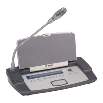
Page 25: Lbb 3547/00 Chairman Conference Unit (Concentus)
| 2-7 Digital Congress Network | Installation and Operating Manual | Chapter 2 - Contribution Equipment LBB 3547/00 Chairman Conference Unit Rear, side and under views (FIG. 2-9 FIG. 2-10) 12. 1 x 3.5 mm jack socket for headset/external microphone (Concentus) 13. - Page 26 | 2-8 Digital Congress Network | Installation and Operating Manual | Chapter 2 - Contribution Equipment Transportable state (collapsed) Rear Left side Microphone release screw (for transportation) Under Right side Not applicable DE-INIT to LBB 3544/00 From next unit...
-
Page 27: Adjustment Setting Conference (Concentus) Units
| 2-9 Digital Congress Network | Installation and Operating Manual | Chapter 2 - Contribution Equipment 2.5.1 Adjustment setting conference (Concentus) units Concentus PCB (Top view rotated 90°) The operational functionality of the delegate conference (Concentus) units LBB 3544/00, LBB 3545/00, LBB 3546/00, and the chairman conference units LBB 3547/00 can be set by solder spots 1070, 1170, 1171 and 1172 located on the units PCB. -
Page 28: Lbb 3549/00, Lbb 3549/50 Pluggable Microphones
| 2-10 Digital Congress Network | Installation and Operating Manual | Chapter 2 - Contribution Equipment LBB 3549/00, LBB 3549/50 Pluggable Microphones LBB 3555/00 Intercom handset The pluggable flexible stem microphones LBB 3549/00 and LBB 3549/50 are unidirectional The Intercom handset enables private two-way vocal communication between conference microphones intended for use with delegate units LBB 3544/00, LBB 3545/00, LBB 3546/00, chairman participants. -
Page 29: Flush-Mounted Contribution Equipment
| 2-11 Digital Congress Network | Installation and Operating Manual | Chapter 2 - Contribution Equipment Flush-mounted Contribution equipment All flush-mounted units are available in standard sizes of 40 x 120 mm (1.57 x 4.72 in) with the exception of the flush-mounted loudspeaker unit LBB 3538/00 which has a dimension of 80 x 120 mm (3.14 x 4.72 in) and the Delegate/chairman voting control panel LBB 3542/00 which has a... -
Page 30: Lbb 3535/00 Dual Audio Interface Unit
| 2-12 Digital Congress Network | Installation and Operating Manual | Chapter 2 - Contribution Equipment LBB 3535/00 Dual Audio Interface unit 10. Initialization LED indicator. The LED illuminates when the unit is not being initialized. The LED is Off when the unit has been initialized. -
Page 31: Flush Mounting Solutions
| 2-13 Digital Congress Network | Installation and Operating Manual | Chapter 2 - Contribution Equipment 2.9.1 Flush Mounting Solutions Connection details: 8-pole 262° DIN-socket PIN 1 - 3 Symmetrical input (PIN 1(signal +), PIN 3 (signal -) Flush mounted solution No.1 (serving two delegate positions) FIG. - Page 32 | 2-14 Digital Congress Network | Installation and Operating Manual | Chapter 2 - Contribution Equipment Flush mounted solution No.3 (floor stand with (interruption) microphones General FIG. 2-20 A hand-held microphone LBB 3536/00 with 5 m cable or LBB 3536/10 with coiled cable can be used instead of a flush mounted Microphone Control Panel with microphone (fixed...
-
Page 33: Lbb 3536/00, /10 Hand-Microphones
| 2-15 Digital Congress Network | Installation and Operating Manual | Chapter 2 - Contribution Equipment 2.10 LBB 3536/00, /10 Hand-microphones 2.11 LBB 3540/15 Multi-purpose connection unit Unidirectional back-plate electret microphones with built-in pop and wind-shield. Both microphones The LBB 3540/15 is intended for use in tailored flush mounted solutions. Its versatility enables a include a microphone on/off button and indicator lamps (LEDs). - Page 34 | 2-16 Digital Congress Network | Installation and Operating Manual | Chapter 2 - Contribution Equipment 4. 20-pole Micromatch connector for connection to: - LBB 3541/00 FM Delegate voting control panel - LBB 3542/00 FM Delegate/Chairman voting control panel with LC-display - Custom-built solutions including push-button and LEDs 5.
-
Page 35: Flush Mounting Solutions
| 2-17 Digital Congress Network | Installation and Operating Manual | Chapter 2 - Contribution Equipment 2.11.1 Flush Mounting Solutions Flush mounted solution No.6 (delegate position) FIG. 2-27 Flush mounted solution No.5 (delegate position) FIG. 2-26 LBB 3540/15 Multi-purpose connection unit LBB 3537/00 Microphone control panel with microphone stem (310mm/12.2 in) - Page 36 | 2-18 Digital Congress Network | Installation and Operating Manual | Chapter 2 - Contribution Equipment Flush mounted solution No.7 (delegate position) FIG. 2-28 Flush mounted solution No.8 (Chairman position) FIG. 2-29 LBB 3540/15 Multi-purpose connection unit LBB 3540/15...
- Page 37 | 2-19 Digital Congress Network | Installation and Operating Manual | Chapter 2 - Contribution Equipment Applicable to solution No.8 1. Jumper J01 on the Multi-purpose connection unit is used to assign the unit for a chairman position. 2. If the chairman needs to view the number of delegates currently speaking or requesting to speak, then the LBB 3542/00 or LBB 3542/20 Voting control panel with alphanumeric LC-display can be used.
-
Page 38: Lbb 3537/00, Lbb 3537/50 Delegate Microphone With Control Panel
| 2-20 Digital Congress Network | Installation and Operating Manual | Chapter 2 - Contribution Equipment 2.12 LBB 3537/00, LBB 3537/50 Delegate microphone with control panel Microphone stem length: The LBB 3537/00 and LBB 3537/50 are uni-directional condenser microphones, mounted on a flush LBB 3537/00 (310 mm / 12.2 in) -
Page 39: Lbb 3537/10 Chairman Microphone With Control Panel
| 2-21 Digital Congress Network | Installation and Operating Manual | Chapter 2 - Contribution Equipment 2.13 LBB 3537/10 Chairman microphone with control 2.14 LBB 3537/20 Pluggable Microphone control panel panel The Pluggable Microphone Control Panel LBB 3537/20 is intended for use with pluggable microphones type LBB 3549/00 and LBB 3549/50. -
Page 40: Lbb 3538/00 Fm Loudspeaker Panel
| 2-22 Digital Congress Network | Installation and Operating Manual | Chapter 2 - Contribution Equipment 2.15 LBB 3538/00 FM Loudspeaker panel 2.16 LBB 3541/00 FM Delegate Voting Control panel The LBB 3538/00 is used to distribute the floor signal when used with flush-mounted units. The panel The LBB 3541/00 includes voting facilities enabling delegates to participate in set voting sessions. -
Page 41: Lbb 3542/00, Lbb 3542/20 Fm Delegate/Chairman Voting Control Panel With Lc-Display
| 2-23 Digital Congress Network | Installation and Operating Manual | Chapter 2 - Contribution Equipment 2.17 LBB 3542/00, LBB 3542/20 1. Assigned Delegate 5 soft-keys marked 1-5 with confirmation indicators (yellow LEDs) for use in combination with FM Delegate/Chairman voting control panel with... -
Page 42: Lbb 3543/15 Fm Chip-Card Reader
| 2-24 Digital Congress Network | Installation and Operating Manual | Chapter 2 - Contribution Equipment 2.18 LBB 3543/15 FM Chip-Card Reader 2.19 LBB 4159/00 Set of 100 Chip Cards Intended for use with the Multi-Purpose Connection UnIt LBB 3540/15, the Flush Mounted Chip The Chip Cards allow delegate identification to the system and access control to the delegate... -
Page 43: Lbb 4157/00 Chip Card Encoder
| 2-25 Digital Congress Network | Installation and Operating Manual | Chapter 2 - Contribution Equipment 2.20 LBB 4157/00 Chip Card Encoder 2.20.1 Position of the DIP switches • Open the DIP compartment under the encoder by lifting the lid. - Page 44 | 2-26 Digital Congress Network | Installation and Operating Manual | Chapter 2 - Contribution Equipment Installing the External Encoder (see FIG. 2-43): CAUTION: Prior to any installation switch-off the computer and remove the mains supply. Serial 1. Connect the serial cable by plugging the RJ46 connector...
-
Page 45: Lbb 3524/00, Lbb 3524/10 And Lbb 3526/10Fm Electronic Channel Selector Panel
| 2-27 Digital Congress Network | Installation and Operating Manual | Chapter 2 - Contribution Equipment 2.21 LBB 3524/00, LBB 3524/10 and LBB 3526/10 FM Electronic channel selector panel All channel selector panels include a 1.5-digit numeric built-in display with up/down select keys for selection of the required language channel. - Page 46 | 2-28 Digital Congress Network | Installation and Operating Manual | Chapter 2 - Contribution Equipment Auto Switch-Off function The unit’s ‘Auto Switch-Off ’ function can be enabled or disabled. If enabled, the unit is switched off by Top view removing headphones from the jack socket.
-
Page 47: Lbb 3525/00 Table Top Housing For Channel Selector Or Voting Control Panel
| 2-29 Digital Congress Network | Installation and Operating Manual | Chapter 2 - Contribution Equipment 2.22 LBB 3525/00 Table top housing for 2.24 LBB 3527/00 Table top housing Channel selector or Voting control panel The table top housing LBB 3527/00 can accommodate 2 flush mounted units with dimensions (H x W) 40 x 120 am (1.57 x 4.72 in). - Page 48 | 2-30 Digital Congress Network | Installation and Operating Manual | Chapter 2 - Contribution Equipment This page has been left blank intentionally Bosch Security Systems | 04-2003 | 3922 988 43318 en LBB 3527/00 Table top housing Get other manuals https://www.bkmanuals.com...
-
Page 49: Interpretation Equipment
| 3-1 Digital Congress Network | Installation and Operating Manual | Chapter 3 - Interpretation Equipment Chapter 3. Interpretation Equipment The DCN system offers comprehensive facilities for simultaneous interpretation and distribution of the interpreted languages to delegates, allowing the system to meet all the demands of international conference and congress venues. - Page 50 | 3-2 Digital Congress Network | Installation and Operating Manual | Chapter 3 - Interpretation Equipment Controls and Indicators LBB 3520/10 VIEWING FUNCTION (see 3-2): 18. Alphanumeric 2-line by 40-character LC-display with back-lighting LISTENING FUNCTIONS Loudspeaker Controls Interconnections 1. Built-in loudspeaker.
- Page 51 | 3-3 Digital Congress Network | Installation and Operating Manual | Chapter 3 - Interpretation Equipment LBB 3520/10 Side view LBB 3520/10 Interconnection Interconnecting Interpreter desks To previous unit From next unit From Intercom handset FIG 3-2 LBB 3520/10 Interpreter desk...
-
Page 52: Removal Cable Guide (Interpreter Desk Lbb 3520/10)
| 3-4 Digital Congress Network | Installation and Operating Manual | Chapter 3 - Interpretation Equipment 3.1.1 Removal cable guide (FIG 3-3) (Interpreter desk LBB 3520/10) Key to Symbols To access the cable guide proceed as follows: 1. Screws A 1. -
Page 53: Lbb 3513/00 Analog Audio Input/Output Module
Digital Congress Network | Installation and Operating Manual | Chapter 3 - Interpretation Equipment 3.1.3 LBB 3513/00 Analog Audio Input/output Module The Analog Audio Input/Output Module type LBB 3513/00 has been designed for use in the BOSCH Digital Congress Network (DCN) system. The module is used to connect external analog audio equipment for distribution through one of the DCN audio distribution channels. - Page 54 | 3-6 Digital Congress Network | Installation and Operating Manual | Chapter 3 - Interpretation Equipment This page has been left blank intentionally Bosch Security Systems | 04-2003 | 3922 988 43318 en LBB 3520/10 Interpreter desk with back-lighting LC-display...
-
Page 55: Central Control Equipment
| 4-1 Digital Congress Network | Installation and Operating Manual | Chapter 4 - Central Control Equipment Chapter 4. Central Control LBB 3500/05, LBB 3500/00(D) and LBB 3500/15, LBB 3500/15(D) Equipment Introduction Central control equipment The Central Control Unit (CCU) is at the heart of the DCN system, and has control facilities for up to 240 contribution units, such as delegate and chairman units, interpreter desks, as well as audio and multipurpose interface units. -
Page 56: Lbb 3500/05, Lbb 3500/05(D) Basic Central Control Unit
| 4-2 Digital Congress Network | Installation and Operating Manual | Chapter 4 - Central Control Equipment LBB 3500/05, LBB 3500/05(D) LBB 3500/15, LBB 3500/15(D) Basic Central Control Unit Central Control Unit The LBB 3500/15 can be used for use in both ‘stand-alone’ discussion systems and PC controlled The LBB 3500/05 is intended for use in stand-alone discussion systems only (i.e. - Page 57 | 4-3 Digital Congress Network | Installation and Operating Manual | Chapter 4 - Central Control Equipment Front panel 1. Mains On/Off switch with indicator (green LED). 2. ‘Active Micros’ 3 indicators (yellow LEDs) and a push-button selector switch to select the maximum number of delegate microphones which may be activated concurrently 1, 2 or 4.
- Page 58 | 4-4 Digital Congress Network | Installation and Operating Manual | Chapter 4 - Central Control Equipment Port 2 not applicable for CCU type LBB 3500/05 Euro mains Euro mains socket socket I/O Control Board I/O Control Board LBB 3500/05 and LBB 3500/15...
-
Page 59: Ccu Mains Voltage And Adjustment
| 4-5 Digital Congress Network | Installation and Operating Manual | Chapter 4 - Central Control Equipment 4.4.1 CCU Mains voltage and adjustment 4.4.2 CCU Mains cable, plug and socket Depending on the CCU version, the CCU on delivery is set ready for use on one of the following... -
Page 60: Ccu Trunk Communication Board (Tcb4)
| 4-6 Digital Congress Network | Installation and Operating Manual | Chapter 4 - Central Control Equipment CCU Trunk Communication Board (TCB4) DIP-switch S14 TCB 4 location 8 7 6 5 4 3 2 1 All CCU’s (LBB 3500/05, LBB 3500/15, LBB 3500/35) include an in-built ‘Trunk Communication Chapter 4.3... -
Page 61: S9 Dip-Switch Settings
| 4-7 Digital Congress Network | Installation and Operating Manual | Chapter 4 - Central Control Equipment 4.5.2 S9 DIP-Switch settings 4.5.3 Jumper settings FIG 4-5 for location, and Table 4-3: for functionality of the DIP-switches. FIG 4-5 for location, and Table 4-4: for functionality of the jumpers. -
Page 62: Cu Protocol And Serial Port Settings
| 4-8 Digital Congress Network | Installation and Operating Manual | Chapter 4 - Central Control Equipment CU Protocol and Serial Port settings 4.6.2 LBB 3500/15 and LBB 3500/35 (TCB 4) - Port 1 : DCN Control PC Port 2 : Camera Control... -
Page 63: Multi-Ccu Card
| 4-9 Digital Congress Network | Installation and Operating Manual | Chapter 4 - Central Control Equipment Multi-CCU card DIP-Switch S13 Table 4-10: DIP-switch S13 The Multi-CCU card installed in the Central Control Unit LBB 3500/35 and LBB 3500/35(D) allows other Multi-CCU’s (max.16) to be connected, thus extending the capacity of the DCN system. - Page 64 | 4-10 Digital Congress Network | Installation and Operating Manual | Chapter 4 - Central Control Equipment DIP-Switch S12 DIP Switch S12 The decimal value assigned to each DIP-switch is as follows: Address Settings 0 to 31 8 7 6 5 4 3 2 1 Select a different address for every CCU installed.
-
Page 65: Connecting Peripheral Equipment To The Ccu
| 4-11 Digital Congress Network | Installation and Operating Manual | Chapter 4 - Central Control Equipment Connecting peripheral equipment to the CCU This section of the page has been left blank intentionally The Central Control Unit can connect to the following external equipment: •... -
Page 66: Ccu Audio Routing Modes
| 4-12 Digital Congress Network | Installation and Operating Manual | Chapter 4 - Central Control Equipment CCU Audio Routing Modes Installation: To set the CCU for the Mix-Minus mode Dip-switch ‘S9’ on the Trunk Communication Board must be set as follows: To provide additional functionality in the CCU, the DCN software from release version 7.01 includes... -
Page 67: Audio Routing Insertion Mode
| 4-13 Digital Congress Network | Installation and Operating Manual | Chapter 4 - Central Control Equipment 4.9.1 Audio Routing INSERTION mode (FIG 4-9) Installation To set the CCU for the ‘INSERTION’ mode DIP-switch ‘S9’ on the Trunk Communication Board (TCB 4) must be set as follows: In the ‘INSERTION’... -
Page 68: Lbb 4106/00, Lbb 4106/00D Extension Power Supply Unit
| 4-14 Digital Congress Network | Installation and Operating Manual | Chapter 4 - Central Control Equipment 4.10 LBB 4106/00, LBB 4106/00D Front view Extension power supply unit The Extension power supply unit is remotely controlled by the CCU and enables systems to be extended. -
Page 69: Lbb 3508/00 & Lbb 3508/00D Audio Media Interface And Power Supply Unit
| 4-15 Digital Congress Network | Installation and Operating Manual | Chapter 4 - Central Control Equipment 4.11 LBB 3508/00 & LBB 3508/00D Audio Media Interface and Power Supply Unit The Audio Media Interface Unit is remotely controlled by the CCU and enables external analogue equipment to be connected to DCN’s digital network - such as broadcast, recording, and sound... -
Page 70: 19" Rack Mounting Dcn Control Units
| 4-16 Digital Congress Network | Installation and Operating Manual | Chapter 4 - Central Control Equipment 4.12 19” Rack Mounting DCN Control Units The Central Control Unit can be rack-mounted into a 19” rack or simply placed on a table-top or similar type surface close to the mains supply. -
Page 71: Chapter 5. Dcn Control Using Personal Computers
| 5-1 Digital Congress Network | Installation and Operating Manual | Chapter 5 - Control using PC Chapter 5. DCN Control using Minimum Software and hardware requirements Table 5-1: PC requirements Personal DCN Control PC For Windows 95, 98 Computers •... -
Page 72: Lbb 3510/00 Pc Network Card
| 5-2 Digital Congress Network | Installation and Operating Manual | Chapter 5 - Control using PC LBB 3510/00 PC Network card When installed into the 8-bit ISA-bus expansion slot of a personal computer (PC) running ‘Windows’ 95 or 98 operating system, the PC network card provides the interface between a PC and the ‘DCN’... -
Page 73: Installing Pc-Network Card
| 5-3 Digital Congress Network | Installation and Operating Manual | Chapter 5 - Control using PC 5.2.1 Installing PC-Network card DCN PC WARNING: Before connecting a computer to the DCN network cabling, ensure the following: Refer also to the ‘Safety Precautions’ found at the front of this manual. -
Page 74: Lbb 3511/00 Pc Card For Multi-Ccu Systems
| 5-4 Digital Congress Network | Installation and Operating Manual | Chapter 5 - Control using PC LBB 3511/00 PC Card for Multi-CCU Systems LED indications (Yellow) Output port 1 indicator, The interface card LBB 3511/00 provides the interface between a master PC and interconnected (Green) Output port 1 indicator, CCUs type LBB 3500/35 only. -
Page 75: Lbb 3511/00 Dip-Switch S12 And S13 Settings
| 5-5 Digital Congress Network | Installation and Operating Manual | Chapter 5 - Control using PC 5.4.2 LBB 3511/00 DIP-switch S12 and S13 settings DIP-switch S13 Table 5-3: DIP-switch S13 For location details see FIG 5-5 LBB 3511/00 PC-card for Multi-CCU systems... -
Page 76: Connection Pc To Ccu
| 5-6 Digital Congress Network | Installation and Operating Manual | Chapter 5 - Control using PC Connection PC to CCU Two methods for connecting the DCN Control PC to the CCU are available: 1. ‘DIRECT’ connection from a serial COM-port of the DCN Control PC to the serial COM-port of the CCU (not applicable for CCU type LBB 3500/05). - Page 77 | 5-7 Digital Congress Network | Installation and Operating Manual | Chapter 5 - Control using PC EXAMPLE 1: SINGLE-CCU system with control PC and Camera control Control PC with Windows 95, 98, NT 4.0 or 2000 9-pole D-type cable connections...
- Page 78 | 5-8 Digital Congress Network | Installation and Operating Manual | Chapter 5 - Control using PC EXAMPLE 2: Multi-CCU System with control PC and Camera control IMPORTANT: The LBB 3510/00 PC Network card CANNOT be used in a PC running...
-
Page 79: Pc Network System
| 5-9 Digital Congress Network | Installation and Operating Manual | Chapter 5 - Control using PC PC NETWORK SYSTEM Software configuration Master CCU PC (OS/2) (Serial Ports 1 and 2) The example below show a typical PC network installation providing more operator control positions. - Page 80 | 5-10 Digital Congress Network | Installation and Operating Manual | Chapter 5 - Control using PC Table 5-9: Two COM-ports (Port 1 and Port 2) Table 5-7: Example CCU_CFG file for ‘DIRECT’ PC and camera control COM-port Remote control...
- Page 81 | 5-11 Digital Congress Network | Installation and Operating Manual | Chapter 5 - Control using PC Table 5-10: DCN Printer and COM-ports for systems using PC-control with PC-Network card LBB 3510/00 (see Chapter 5.7 Chapter 5.8) LASER PRINTER MATRIX PRINTER CARD ENCODER/ AUX.- INTERFACE...
- Page 82 | 5-12 Digital Congress Network | Installation and Operating Manual | Chapter 5 - Control using PC Table 5-11: DCN Printer and COM-ports for systems using ‘DIRECT’ PC control (see Chapter 5.7 Chapter 5.8) LASE RPRINTER MATRIX PRINTER CARD ENCODER/ AUX.- INTERFACE...
-
Page 83: Connecting Peripheral Devices
| 5-13 Digital Congress Network | Installation and Operating Manual | Chapter 5 - Control using PC Connecting Peripheral devices Serial Printer/Card encoder 9-pole - 25 pole MATRIX printer (COM 1* or COM 2*) Connects via a serial port (COM1* or COM... - Page 84 | 5-14 Digital Congress Network | Installation and Operating Manual | Chapter 5 - Control using PC This page has been left blank intentionally Bosch Security Systems | 04-2003 | 3922 988 43318 en Connecting Peripheral devices Get other manuals https://www.bkmanuals.com...
-
Page 85: Chapter 6. Dcn Camera Control
| 6-1 Digital Congress Network | Installation and Operating Manual | Chapter 6 - DCN Camera Control Chapter 6. DCN Camera Series 19” rack height European version US version (220 - 240 VAC) (120 VAC) Control LTC 8100 LTC 8100/50 LTC 8100/60 The ‘DCN Automatic Camera Control (DACC) directs video cameras toward speaking conference... -
Page 86: Installation
| 6-2 Digital Congress Network | Installation and Operating Manual | Chapter 6 - DCN Camera Control A maximum of 4 audience video displays can be connected to the Allegiant video switcher (not applicable for video switcher LTC 8100 series) using outputs 2 to 5. The actual number set is defined Rear Panel Video Switcher LTC8100 in the DCN Camera Control software LBB 3562 or LBB 3588. - Page 87 | 6-3 Digital Congress Network | Installation and Operating Manual | Chapter 6 - DCN Camera Control ALLEGIANT® VIDEO SWITCHING/CONTROL EQUIPMENT DACC for Camera Configuration only: Software Stand-alone systems Manuals Front Panel Video Switcher LTC8200 LBB 3562/00 ALLEGIANT Video System...
-
Page 88: Set-Up Camera Configuration
| 6-4 Digital Congress Network | Installation and Operating Manual | Chapter 6 - DCN Camera Control 6.1.4 Set-up Camera configuration 9 pole D-type Video Switcher Single CCU to Video Switcher Reference: To configure and set-up camera positions according to delegate/chairman... - Page 89 | 6-5 Digital Congress Network | Installation and Operating Manual | Chapter 6 - DCN Camera Control Camera Control 6.1.4.6 Installation of Camera Control in DCN system with PC control CCU = 1 // COM-port 1 . . 4 1.
-
Page 90: Direct Camera Control
| 6-6 Digital Congress Network | Installation and Operating Manual | Chapter 6 - DCN Camera Control Direct Camera Control AutoDome Camera With Direct Camera Control (DCC) it is possible to connect one AutoDome camera directly to a Single CCU AutoDome Camera CCU. -
Page 91: Set-Up Camera Configuraion
| 6-7 Digital Congress Network | Installation and Operating Manual | Chapter 6 - DCN Camera Control 6.2.4 Set-up Camera Configuraion 8. Disconnect the CCU from the PC. 9. Connect the AutoDome to the CCU. Reference: To configure and set-up camera positions according to delegate/chairman... -
Page 92: Switching Options Using A Personal Computer
| 6-8 Digital Congress Network | Installation and Operating Manual | Chapter 6 - DCN Camera Control Switching options using a personal computer Key to symbols Using the communication port (COM-port 2) of a PC, a wide variety of communication and 1. -
Page 93: Dcn Installation Accessories
| 7-1 Digital Congress Network | Installation and Operating Manual | Chapter 7 - DCN Installation Accessories Chapter 7. DCN Installation Introduction Installation accessories DCN’s installation accessories allows system installation to be simplified with the use of ready made accessories cables complete with connectors. -
Page 94: Lbb 4114/00 Trunk-Cable Splitter
| 7-2 Digital Congress Network | Installation and Operating Manual | Chapter 7 - DCN Installation Accessories 7.1.1 LBB 4114/00 Trunk-cable splitter 7.1.2 LBB 4115/00 Tap-off Unit For use in combination with the systems installation cabling, the splitter is used to divide the trunk-line The LBB 4115/00 is used to create short-circuit proof tap-off points on the trunk-line cabling. -
Page 95: Cable Assemblies And Connectors
| 7-3 Digital Congress Network | Installation and Operating Manual | Chapter 7 - DCN Installation Accessories 7.1.3 Cable assemblies and connectors Cable Connection details: The following Cable assemblies are available with the DCN system. LBB 4116/00 Installation cable (100 m (328 ft.) without connectors) -
Page 96: Connectors
| 7-4 Digital Congress Network | Installation and Operating Manual | Chapter 7 - DCN Installation Accessories 7.1.4 Connectors The 6-pole moulded circular connectors, male and female include a plug locking facility for use with cable locking clamps LBB 4117/00. -
Page 97: Information Displays
| 8-1 Digital Congress Network | Installation and Operating Manual | Chapter 8 - Information Displays Chapter 8. Information LBB 3512/00 Data Distribution Board The data distribution board provides the communication interface between the DCN system and Displays externally connected peripheral equipment - such as hall displays, remote switching panels and tailored conference solutions. - Page 98 | 8-2 Digital Congress Network | Installation and Operating Manual | Chapter 8 - Information Displays Electrical requirements 9. Parallel output connector via 20 solder pads (open collector outputs). • Supply voltage (optional):10 - 40 V d.c. 10. Initialization button with LED indicator to indicate the none initialized mode.
-
Page 99: Remote Switching Solutions
| 8-3 Digital Congress Network | Installation and Operating Manual | Chapter 8 - Information Displays Data Format Specifications: RS232 Output 8.1.1 Remote Switching Solutions • 9600/19200 baud (selected by dip switch) Using the Data Distribution Board LBB 3512/00 an interface facility is provided for the control of •... -
Page 100: Installing Data Distribution Board Lbb 3512/00
| 8-4 Digital Congress Network | Installation and Operating Manual | Chapter 8 - Information Displays 8.1.2 Installing Data Distribution board LBB 3512/00. 8.1.3 Connecting Hall Displays to the DCN System To install the board, first mount and secure the board in a convenient position inside the relevant hall... -
Page 101: Interconnection For Video Hall Displays And Video Projectors
| 8-5 Digital Congress Network | Installation and Operating Manual | Chapter 8 - Information Displays 8.1.4 Interconnection for Video hall displays and Video Projectors Refer to FIG 8-9. To display information on a Video hall display or Video projector: Use the VGA/SVGA output of a client computer, other than the one used as the main DCN central computer. - Page 102 | 8-6 Digital Congress Network | Installation and Operating Manual | Chapter 8 - Information Displays This page has been left blank intentionally Bosch Security Systems | 04-2003 | 3922 988 43318 en LBB 3512/00 Data Distribution Board Get other manuals https://www.bkmanuals.com...
-
Page 103: Dcn Peripheral Equipment
| 9-1 Digital Congress Network | Installation and Operating Manual | Chapter 9 - DCN Peripheral Equipment Chapter 9. DCN Peripheral Equipment Front view Introduction Peripheral Equipment The DCN system can be connected to various external devices including a telephone coupler. - Page 104 | 9-2 Digital Congress Network | Installation and Operating Manual | Chapter 9 - DCN Peripheral Equipment This page has been left blank intentionally Bosch Security Systems | 04-2003 | 3922 988 43318 en Introduction Peripheral Equipment Get other manuals https://www.bkmanuals.com...
-
Page 105: Installation Techniques
| 10-1 Digital Congress Network | Installation and Operating Manual | Chapter 10 - Installation Techniques Chapter 10. Installation 10.1 Introduction Installation Techniques The primary focus of this chapter is to provide system installation techniques, typical examples, and Techniques... -
Page 106: Power Handling Capacity
| 10-2 Digital Congress Network | Installation and Operating Manual | Chapter 10 - Installation Techniques 10.2 Power Handling Capacity To understand the power handling capacity of a system, individual DCN units have been assigned with LBB 3500/xx Central Control Unit LBB 3508/00 Audio Media Interface Unit a Power Consumption Factor (PCF). -
Page 107: Trunk Outlets And Tap-Offs
| 10-3 Digital Congress Network | Installation and Operating Manual | Chapter 10 - Installation Techniques 10.3 Trunk outlets and Tap-offs The Extension Power Supply Unit LBB 4106/00, Audio Media Interface Unit LBB 3508/00, Trunk-cable splitter LBB 4114/00 and Tap-off Unit LBB 4115/00 all have Trunk outlets and Tap-offs. Trunk-outlets LBB 3508 Audio Media Interface Unit are used for loop-through of the DCN trunk-line, and tap-offs are used for trunk-cable splitting. - Page 108 | 10-4 Digital Congress Network | Installation and Operating Manual | Chapter 10 - Installation Techniques Max. number of units connected in series (without the use of extension cables) LBB 3500/xx Central Control Unit The maximum number of units connected in series to a Trunk outlet or Tap-off of a CCU (LBB 3500), Extension Power Supply unit (LBB 4106/00) and Audio Media Interface unit (LBB 3508/00) is: Rec.
-
Page 109: Using Tap-Off Unit Lbb 4115/00
| 10-5 Digital Congress Network | Installation and Operating Manual | Chapter 10 - Installation Techniques 10.3.2 Using Tap-Off unit LBB 4115/00 10.3.3 Maximum cable lengths using Trunk-outlets and/or Tap-offs The Tap-off unit LBB 4115/00 (FIG 10-5) provides short-circuit protection on the Tap-off connector. -
Page 110: Calculating The Pcf Of A System With Respect To Cable Length
| 10-6 Digital Congress Network | Installation and Operating Manual | Chapter 10 - Installation Techniques 10.4 Calculating the PCF of a System with respect to cable Calculation Method • Using the PCF table (Table 10.1) and the graph... - Page 111 | 10-7 Digital Congress Network | Installation and Operating Manual | Chapter 10 - Installation Techniques SYSTEM USING SYSTEM USING Port 1 Rec. Line Rec. Line Trunk Port 1 Trunk DISCUSSION UNITS CONCENTUS LBB 3505/05 LBB 3500/15, LBB 3500/35...
-
Page 112: Graph Explanation
| 10-8 Digital Congress Network | Installation and Operating Manual | Chapter 10 - Installation Techniques Rec. Line Port 1 Trunk 115 V-T4A 230 V -T2A Symmetrical LBB 3500/xx Trunk splitter LBB 4114/00 100 m (328 ft.) Regenerative ‘Tap-offs’... -
Page 113: Graph Reference Examples
| 10-9 Digital Congress Network | Installation and Operating Manual | Chapter 10 - Installation Techniques 10.4.3 Graph reference examples GRAPH REFERENCE Y axis X axis (max.) Ext. Cable (m) BLOCK DIAGRAMS PCF CALCULATION FIG 10-12 in combination with the PCF graph... -
Page 114: Control Capacity
| 10-10 Digital Congress Network | Installation and Operating Manual | Chapter 10 - Installation Techniques 10.5 Control Capacity 10.6 Stand-alone Systems The Central Control Unit LBB 3500/05 has a power handling capacity to power up to 90 DCN units,... -
Page 115: System Layout (Without Extension Units)
| 10-11 Digital Congress Network | Installation and Operating Manual | Chapter 10 - Installation Techniques 10.6.2 System layout (without extension units) 10.6.3 System with Extension units Using extension cables, Trunk-splitters and Tap-off units, the length of cable on a system unit can be... -
Page 116: Computer Based Systems
| 10-12 Digital Congress Network | Installation and Operating Manual | Chapter 10 - Installation Techniques 10.7 Computer Based Systems IN-DIRECT Connection using PC Network card LBB 3510/0 The DCN 2000 system offers two methods for connecting a central control PC to the DCN system: DIRECT and IN-DIRECT. - Page 117 | 10-13 Digital Congress Network | Installation and Operating Manual | Chapter 10 - Installation Techniques PC system for 270 PCF This page has been left blank intentionally FIG 10-18 shows a PC system catering for 270 PCF. An Audio Media Interface Unit LBB 3508/00 is used to extend the system by 90 PCF.
-
Page 118: Pc Network System
| 10-14 Digital Congress Network | Installation and Operating Manual | Chapter 10 - Installation Techniques 10.7.1 PC Network System In installations where more than one PC operator control position is required, an additional PC can LBB 3500/15 or LBB 3500/35 be connected via a ‘Peer-to-Peer’... -
Page 119: Multi-Ccu System
| 10-15 Digital Congress Network | Installation and Operating Manual | Chapter 10 - Installation Techniques FIG 10-19 Typical solution providing more control positions PC dedicated for Multi-CCU’s 10.8 Multi-CCU system Multi-CCU caters for situations where more than 240 contribution units are required. Multi-CCU UPS (Uninterrupted Power Supply) recommended systems are controlled from a separate, dedicated PC running OS.2 version 3.00 Warp operating... -
Page 120: Remote Controller
| 10-16 Digital Congress Network | Installation and Operating Manual | Chapter 10 - Installation Techniques FIG 10-20 Multi-CCU configuration and connection and the ‘Remote controller’ should not exceed 5 m (16.4 ft.). Where longer distances are required an ‘interface unit’... -
Page 121: Typical Examples Using The Remote Controller
| 10-17 Digital Congress Network | Installation and Operating Manual | Chapter 10 - Installation Techniques OPEN INTERFACE PC dedicated for Multi-CCU’s 2. Multi- CCU System (FIG 10-22) Remote PC UPS (Uninterrupted Power Supply) A null-modem RS-232 cable is used to connect the ‘Master CCU PC’ to the remote controller. The recommended maximum cable length between the ‘Master CCU PC’... -
Page 122: Interconnecting Interpretation Equipment
| 10-18 Digital Congress Network | Installation and Operating Manual | Chapter 10 - Installation Techniques 10.10 Interconnecting Interpretation Equipment A maximum of six desks can be installed per interpreter booth. The desk can be used stand-alone or From next unit as part of a more comprehensive system.). -
Page 123: Language Distribution Equipment
| 10-19 Digital Congress Network | Installation and Operating Manual | Chapter 10 - Installation Techniques 10.11 Language Distribution Equipment Integrus digital infra red system An infra-red system comprises an infra-red transmitter, several radiators and infra-red receivers carried by delegates. A well balanced installation should be based on sufficient direct radiation 10.11.1 Introduction... -
Page 124: Installation
| 10-20 Digital Congress Network | Installation and Operating Manual | Chapter 10 - Installation Techniques 10.11.2 Installation Flush Mounted Language Distribution The main component in a flush-mounted wired language distribution system is the Electronic Channel Distribution of the interpreted languages to conference delegates can be distributed by using a wired Selector Panel LBB 3524/xx. - Page 125 | 10-21 Digital Congress Network | Installation and Operating Manual | Chapter 10 - Installation Techniques 2. Integrus digital Infra red system For further detailed information when installing an IIntegrus digital infra-red system - particularly on positioning radiators, and operating the system - refer to the Installation and Operating Manual Integrus Digital Infra Red Distribution System, Code No.
- Page 126 | 10-22 Digital Congress Network | Installation and Operating Manual | Chapter 10 - Installation Techniques This page has been left blank intentionally Bosch Security Systems | 04-2003 | 3922 988 43318 en Language Distribution Equipment Get other manuals https://www.bkmanuals.com...
-
Page 127: Chapter 11. System Set-Up & Operation
| 11-1 Digital Congress Network | Installation and Operating Manual | Chapter 11 - System Set-up and Operation Chapter 11. System Set-up & NOTE: After the initialization process, it is recommended that the function of each active unit installed is checked individually. -
Page 128: Setting Up A Stand-Alone System
| 11-2 Digital Congress Network | Installation and Operating Manual | Chapter 11 - System Set-up and Operation 11.2 Setting up a stand-alone system 2. .‘Override’ mode When the ‘Override mode is selected, delegates activate their microphones by pressing the The Central Control unit, in stand alone systems enables four basic conference procedures to be microphone button on their delegate units. -
Page 129: Multi-Ccu Set-Up For The First-Time
| 11-3 Digital Congress Network | Installation and Operating Manual | Chapter 11 - System Set-up and Operation 11.3 Multi-CCU Set-up for the first-time. 11.3.1 Downloading Control PC-software Before you begin to work for the first time, ensure that all CCU’s have the same firmware. To Proceed as follows: download the software from the DCN control PC to all CCU’s in the system, select the ‘Single’... -
Page 130: To Set System Default Language
| 11-4 Digital Congress Network | Installation and Operating Manual | Chapter 11 - System Set-up and Operation When the selected units <RETURN> softkey has been pressed the CCU reverts back into the 4. To select and confirm the default congress operational mode. -
Page 131: Sound Management
| 11-5 Digital Congress Network | Installation and Operating Manual | Chapter 11 - System Set-up and Operation 11.5 Sound Management REMARKS: 1.The frequency response of a room is dependent on the position of microphone and loud- 11.5.1 Equalizer function speaker used, particularly if a microphone is relative close to a loudspeaker. -
Page 132: Additional Stand-Alone Operations (Applicable To Conference Units Only)
| 11-6 Digital Congress Network | Installation and Operating Manual | Chapter 11 - System Set-up and Operation 11.6 Additional stand-alone operations (applicable to confer- ence units only) 11.6.1 Voting modes The DCN system in stand-alone operation offers an electronic voting procedure to meet the majority of conference requirements. -
Page 133: Delegate/Chairman Unit Operation (Conference Units Only)
| 11-7 Digital Congress Network | Installation and Operating Manual | Chapter 11 - System Set-up and Operation 11.7 Delegate/Chairman unit operation (Conference units only) 11.7.1 Introduction Microphone management as its term suggest, refers to the technique of managing and controlling the different methods by which delegates are able to use their microphone units. -
Page 134: Operation Delegate Units Lbb 3544/00, Lbb 3545/00, Lbb 3546/00
| 11-8 Digital Congress Network | Installation and Operating Manual | Chapter 11 - System Set-up and Operation 11.7.2 OPERATION Delegate Units LBB 3544/00, LBB 3545/00, LBB 3546/00 Microphone ON ID Chip-card reader indicator** Side view Loudspeaker (muted when... - Page 135 | 11-9 Digital Congress Network | Installation and Operating Manual | Chapter 11 - System Set-up and Operation OPERATION Delegate units LBB 3544/00, LBB LANGUAGE CHANNEL SELECT* LBB 3546/00 unit with display Insert headphones to switch-on the units numeric LC display. In...
- Page 136 | 11-10 Digital Congress Network | Installation and Operating Manual | Chapter 11 - System Set-up and Operation MAIN MENU LED status during voting procedure MICRO MESSAGE only displayed if MESSAGE ( FLASHING message sent from PC-operator) INTERCOM OPERATION...
- Page 137 | 11-11 Digital Congress Network | Installation and Operating Manual | Chapter 11 - System Set-up and Operation 11.7.3 OPERATION Chairman Unit LBB 3547/00 Microphone ON ID Chip-card reader indicator** Side view Loudspeaker (muted when microphone is ON) Graphic LC-display...
-
Page 138: Operation Chairman Unit Lbb 3547/00
| 11-12 Digital Congress Network | Installation and Operating Manual | Chapter 11 - System Set-up and Operation OPERATION CHAIRMAN UNIT LBB 3547/00 LANGUAGE CHANNEL SELECT • MESSAGE Use the units numeric LC display in combination with its select up/ A yellow LED flashes (adjacent softkey 4) , if a message has been... - Page 139 | 11-13 Digital Congress Network | Installation and Operating Manual | Chapter 11 - System Set-up and Operation MAIN MENU LED status during voting procedure VOTING MICRO MESSAGE FLASHING Press key Incoming MESSAGE Indication (yellow flashing) VOTING MENU MICRO MENU from PC operator.
-
Page 140: Operating Delegate/Chairman Units (Discussion Units Only)
| 11-14 Digital Congress Network | Installation and Operating Manual | Chapter 11 - System Set-up and Operation 11.8 Operating Delegate/Chairman units (Discussion units only) For unit description (see Chapter 2.2 Chapter 2.2) 11.8.1 Microphone • Press the microphone button to switch on the microphone. -
Page 141: Interpretation
| 11-15 Digital Congress Network | Installation and Operating Manual | Chapter 11 - System Set-up and Operation 11.9 Interpretation 11.9.4 Microphone locks In its programming mode, the desk can be programmed with a microphone ‘Override’ or microphone The interpreter desk has two functional modes: the operational mode and the programming mode. In ‘Interlock’... - Page 142 | 11-16 Digital Congress Network | Installation and Operating Manual | Chapter 11 - System Set-up and Operation Out-going B-select Incoming channel Out-going A-select External message Microphone with Alphanumeric Incoming channel key with LED preselect keys with key with LED...
-
Page 143: Operating The Interpreter Desk
| 11-17 Digital Congress Network | Installation and Operating Manual | Chapter 11 - System Set-up and Operation 11.10 Operating the Interpreter Desk 11.10.1 Incoming Channel Selection ENGLISH Using the desks three Incoming channel pre-select keys, , the interpreter can quickly select, English one of three familiar incoming languages for translations. -
Page 144: Interpreter Desk Listening
| 11-18 Digital Congress Network | Installation and Operating Manual | Chapter 11 - System Set-up and Operation 11.10.6 Outgoing Channel Selection The display below shows the interpreter’s desk in its operational mode, displaying three incoming language channels. Channel 2ENG, channel 3FR, and Channel 4GER. For a list of language... -
Page 145: Typical Displays Showing Outgoing Channels
| 11-19 Digital Congress Network | Installation and Operating Manual | Chapter 11 - System Set-up and Operation 11.10.7 Typical Displays showing outgoing channels When programmed None, no override or interlock facility is available, this means that interpreters assigned with the same outgoing channel are able to access the output channel and switch on their The following display shows the interpreter desk displaying both the incoming language channels and microphones simultaneously. -
Page 146: Programming The Interpreter Desk
| 11-20 Digital Congress Network | Installation and Operating Manual | Chapter 11 - System Set-up and Operation 11.11 Programming the Interpreter desk In PC based systems only the Menu (Select booth number) and the Menu (select desk number) need to be programmed manually on each desk. -
Page 147: Entering The Desks Programming Mode
| 11-21 Digital Congress Network | Installation and Operating Manual | Chapter 11 - System Set-up and Operation 11.11.2 Entering the desks programming mode 11.11.3 Menu Programming procedures Before attempting to program the interpreter desk, ensure that the system has first been initialized Initializing). - Page 148 | 11-22 Digital Congress Network | Installation and Operating Manual | Chapter 11 - System Set-up and Operation MENUS Menu b. SELECT BOOTH NUMBER To assign the interpreter desk to a specific booth. Each interpreter desk installed in the system needs Menu a.
- Page 149 | 11-23 Digital Congress Network | Installation and Operating Manual | Chapter 11 - System Set-up and Operation Menu c. SELECT DESK NUMBER WITHIN A BOOTH Menu d. SELECT NUMBER OF CHANNELS To assign the interpreter desk with a specific number within a booth. Each interpreter desk installed To set the number of language channels.
- Page 150 | 11-24 Digital Congress Network | Installation and Operating Manual | Chapter 11 - System Set-up and Operation Menu e. Select language list Menu f. Select language for channel To select a list of languages and their abbreviations for display in either ‘English’, ‘French’ or in their To assign languages (up to 11 channels for stand-alone systems) to a channel for selection by the ‘Original’...
- Page 151 | 11-25 Digital Congress Network | Installation and Operating Manual | Chapter 11 - System Set-up and Operation Table 11.1 Language and Abbreviations Menu g. Select outgoing channel via A-output To set the desk’s A-output channel number. The number set is only for the desk being programmed.
- Page 152 | 11-26 Digital Congress Network | Installation and Operating Manual | Chapter 11 - System Set-up and Operation Menu h. Select outgoing channel(s) via B-output Menu j. Select number of auto-relay booth(s) To set the interpreter’s B-output. The B-output can be assigned to NONE or to ALL channels Selecting this menu the number of booths supplying an auto-relay function can be assigned.
- Page 153 | 11-27 Digital Congress Network | Installation and Operating Manual | Chapter 11 - System Set-up and Operation Menu k. Select auto-relay booth Menu l. Select microphone locks between booths This function is only available if in Menu J, ‘Select number of auto-relay booth(s)’ is set to either Using this menu ‘Select microphone locks between booths’...
- Page 154 | 11-28 Digital Congress Network | Installation and Operating Manual | Chapter 11 - System Set-up and Operation This page has been left blank intentionally Bosch Security Systems | 04-2003 | 3922 988 43318 en Programming the Interpreter desk...
-
Page 155: Environmental Conditions And Maintenance
| 12-1 Digital Congress Network | Installation and Operating Manual | Chapter 12 - Environmental Conditions & Maintenance Chapter 12. Environmental NOTE: Acoustic feedback, causing ‘Larsen’ effect (howling), is possible when connected headphones/headsets reproducing the floor channel with a high volume, come too close to an activated microphone. -
Page 156: Interpreter Booths
| 12-2 Digital Congress Network | Installation and Operating Manual | Chapter 12 - Environmental Conditions & Maintenance 12.4 Interpreter booths 12.5 Ventilation Pressure and speed of work at most international conferences means that interpreters have to take Maintain good ventilation. Ventilation holes are provided on top of the central control units. Place the turn and turn about to keep pace and ensure a steady flow of smooth interpretation. -
Page 157: Technical Data
| 13-1 Digital Congress Network | Installation and Operating Manual | Chapter 13 - Technical Data Chapter 13. Technical Data 13.1.2 Mounting brackets (included with type No.s LBB 3500/xx, LBB 4106/00, LBB 3508) Mounting brackets used for mounting central control equipment, and extension units. -
Page 158: Lbb 4106/00 And Lbb 4106/00 (D)
| 13-2 Digital Congress Network | Installation and Operating Manual | Chapter 13 - Technical Data 13.1.3 LBB 4106/00 and LBB 4106/00 (D) 13.2 Table-top units Extension Power Supply Unit 13.2.1 Conference Units Mounting Free standing on a table-top or mounted into a 19-inch rack. -
Page 159: Lbb 3536/Xx Hand Microphones
| 13-3 Digital Congress Network | Installation and Operating Manual | Chapter 13 - Technical Data 13.2.4 LBB 3536/xx Hand microphones 13.2.7 LBB 3527/00 Table-top housing for FM loudspeaker panel Dimensions Diam x H 28 x 265 mm ( 1.1 x 10.4 in) Excl. cable Mounting: Free standing, or fixed on a table using the unit’s screw mounting... -
Page 160: Flush Mounted Equipment
| 13-4 Digital Congress Network | Installation and Operating Manual | Chapter 13 - Technical Data 13.3 Flush Mounted Equipment 13.3.2 LBB 3526/10 FM Electronic Channel Selector Panel Mounting Flush mounting using the units click-to-fit mechanism in a metal 13.3.1 LBB 3524/00 and LBB 3424/10 FM Electronic Channel Selector Panel... -
Page 161: Lbb 3537/00 And Lbb 3537/50 Microphone With Fm Control Panel
| 13-5 Digital Congress Network | Installation and Operating Manual | Chapter 13 - Technical Data 13.3.3 LBB 3537/00 and LBB 3537/50 Microphone with FM Control Panel 13.3.4 LBB 3537/10 FM Chairman Priority Control Panel Mounting Flush mounting using the units click-to-fit mechanism in a metal Mounting Flush mounting using the units click-to-fit mechanism in a metal... -
Page 162: Lbb 3537/20 And Lbb 3537/50 Fm Microphone Control Panel For Microphones Lbb 3549/00 And Lbb 3549/50
| 13-6 Digital Congress Network | Installation and Operating Manual | Chapter 13 - Technical Data 13.3.6 LBB 3537/20 and LBB 3537/50 FM Microphone Control Panel 13.3.7 LBB 3538/00 FM Loudspeaker panel for microphones LBB 3549/00 and LBB 3549/50 Mounting Flush mounting using the units click-to-fit mechanism in a metal... -
Page 163: Lbb 3540/15 Multi-Purpose Connection Unit
| 13-7 Digital Congress Network | Installation and Operating Manual | Chapter 13 - Technical Data 13.3.8 LBB 3540/15 Multi-purpose Connection Unit 13.3.10 LBB 3542/00 FM Delegate/Chairman Voting Control Panel with LC-display Mounting Free standing on a table-top, flush mounting, floor or wall mounting. -
Page 164: Lbb 3543/15 Chip Card Reader
| 13-8 Digital Congress Network | Installation and Operating Manual | Chapter 13 - Technical Data 13.3.11 LBB 3543/15 Chip Card Reader 13.4 Installation Accessories Mounting Flush mounting using the units click-to-fit mechanism in a metal 13.4.1 LBB 4114/00Trunk Cable Splitter LBB 4115/00 Tap-off Unit panel with a thickness of 2 mm (0.07 in), or flush mounting in a... -
Page 165: Electrical Data
| 13-9 Digital Congress Network | Installation and Operating Manual | Chapter 13 - Technical Data 13.5 Electrical data Interpreter headphones LBB9095/30 Impedance:2 x 720 Ohms Frequency response:250 Hz to13 kHz (-10 dB) 13.5.1 Microphones (General) Max. power:200 mW Freq. -
Page 166: Combined Units
| 13-10 Digital Congress Network | Installation and Operating Manual | Chapter 13 - Technical Data 13.5.4 Combined units NOTE: The maximum operational temperature for ALL operational contribution units with LC-display is 40°C. The maximum operational temperature for the Ext. Power supply •... -
Page 167: System Limitations
| 13-11 Digital Congress Network | Installation and Operating Manual | Chapter 13 - Technical Data 13.6 System limitations 13.7 Connection details 13.7.1 Mains cable 1. The maximum length of cable (including the 2 m cable attached to the DCN system units) that can be connected to a tap-off outlet of a Central Control Unit LBB 3500/.., Audio Media Interface... -
Page 168: Concentus Units
| 13-12 Digital Congress Network | Installation and Operating Manual | Chapter 13 - Technical Data 13.7.5 CONCENTUS units 13.7.8 Jack-plug 5-pole XLR connector (female) for 1. TIP: Signal (live) pluggable microphones LBB 3549/xx 2. RING: Signal (return) 3. Sleeve:... -
Page 169: Available Audio Down Link Channels
| 13-13 Digital Congress Network | Installation and Operating Manual | Chapter 13 - Technical Data 13.8 Available Audio Down Link Channels Table 13-1: Available audio down link channels + = Audio outputs Audio Outputs The DCN system has a total of 16 down-link audio channels (numbered 0 - 15). -
Page 170: Template For Table Cut-Out Of Concentus Units
| 13-14 Digital Congress Network | Installation and Operating Manual | Chapter 13 - Technical Data 13.9 TEMPLATE FOR TABLE CUT-OUT OF CONCENTUS UNITS CHECK DIMENSION ! This template is for use in making a cut-out’ in a desk or table-top for flush-mounting CONCENTUS units. - Page 171 Get other manuals https://www.bkmanuals.com...
- Page 172 For more information please visit www.boschsecuritysystems.com © 2003 Bosch Security Systems B.V. Data subject to change without notice 04-2003 | 3922 988 43318 en Get other manuals https://www.bkmanuals.com...
Need help?
Do you have a question about the Digital Congress Network and is the answer not in the manual?
Questions and answers
Where do I find digital congress network in Lagos?