Advertisement
Quick Links
Operator's
Manual
DANGER is used in this manual to warn of high
voltages capable of causing shock, burns, or death.
WARNING is used in this manual to warn
of possible personal injury.
CAUTION is used in this manual to warn
of possible equipment damage.
50 Hanover Road, Florham Park, New Jersey 07932-1591 USA
For sales or service call 1 800 800-2726 (ASCO) www.ascopower.com
ASCO POWER TECHNOLOGIES CANADA PO Box 1238, 17 Airport Road, Brantford, Ontario, Canada N3T 5T3
telephone 519 758-8450, fax 519 758-0876, for service call 1 888 234-2726 (ASCO)
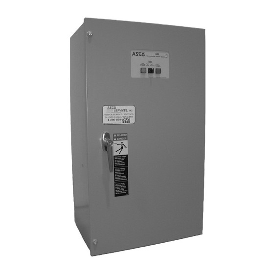
Series 386 Electrically-Operated
Non-Automatic Transfer Switches
D-design 30 through 230 amps
30-200 amp sizes
Get other manuals https://www.bkmanuals.com
Note:
Refer to the outline and wiring drawings
provided with your ASCO Series 386 Non-Automatic
Transfer Switch for all installation and connection
details and accessories.
An experienced licensed electrician must install the Non-
Automatic Transfer Switch.
Rating Label
Each Non-Automatic Transfer Switch contains a rating label
to define the loads and fault circuit withstand/closing ratings.
Refer to the label on the Transfer Switch for specific values.
Do not exceed the values on the rating label.
Exceeding the rating can cause personal injury
or serious equipment damage.
Identification Label
The identification label on the Transfer Switch includes
data for each specific ASCO Series 386. Use the switch only
within the limits shown on identification label.
TABLE OF CONTENTS
. . . . . . . . . . . . . . . . . . . . . . . .
. . . . . . . . . . . . . . . . . . . . . . . .
. . . . . . . . . . . . . . . . . . . . . . .
. . . . . . . . . . . . . . . . . . . . . . .
. . . . . . . . . . . . . . . . . . . . . . . . .
www.asco.ca
1-1
1-2
. . . . . . . . . . .
2-1
. . . . . . . . . . . . . . . . . .
3-1
3-2
4-1
. . . . . . . . . . . . . . . . .
5-1
back cover
381333-230 C
Advertisement

Related Manuals for Asco 386 Series


Summary of Contents for Asco 386 Series
-
Page 1: Table Of Contents
381333–230 C For sales or service call 1 800 800–2726 (ASCO) www.ascopower.com ASCO POWER TECHNOLOGIES CANADA PO Box 1238, 17 Airport Road, Brantford, Ontario, Canada N3T 5T3 telephone 519 758–8450, fax 519 758–0876, for service call 1 888 234–2726 (ASCO) www.asco.ca... - Page 2 Catalog Number Identification Typical ASCO 386 catalog no. for solid neutral, 3 pole, 150 amp, 480 V, N–ATS in Type 1 enclosure: D 386 Neutral Phase Poles Amperes Voltage Controller Enclosure – solid – single Ø – standard – type 1 –...
- Page 3 Catalog Number Identification Typical ASCO 386 catalog no. for solid neutral, 3 pole, 230 amp, 480 V, N–ATS in Type 1 enclosure: D 386 Neutral Phase Poles Amperes Voltage Controller Enclosure – solid – single Ø – standard – type 1 –...
-
Page 4: Installation
(two plugs). the cables being installed. Standard terminal lugs are solderless screw type and will accept the wire sizes listed on the drawings provided with the ASCO 386. Be careful Auxiliary Circuits when stripping insulation from the cables; avoid nicking or ringing the conductor. -
Page 5: Functional Test
INSTALLATION (continued) Functional Test The Functional Test consists of three checks: manual Position of the transfer switch is indicated here operation, voltage checks, and electrical operation. weight marked N (normal) and E (emergency) Do these checks in the order presented to avoid damaging the non–automatic transfer switch. - Page 6 3. Turn the door-mounted Transfer Control switch tor according to the manufacturer’s recommendations. counterclockwise to Transfer To Normal. The ASCO 386 will respond only to the rated voltage specified on the Transfer Switch nameplate. 4. The transfer switch will operate back to the Normal 5.
-
Page 7: Sequence Of Operation
SECTION 2 SEQUENCE OF OPERATION Controller Code 1 Refer to Section 5, Optional Accessories for additional control functions. Refer to Wiring Diagram furnished with the ASCO 386. Note Control Features furnished on this switch, and review operation. Transfer Transfer Control... -
Page 8: Testing & Service
Serial No., Bill of Material No. preventive maintenance program is recommended. (BOM), and Catalog No. from the transfer switch name- plate. Contact your local ASCO Power Technologies sales office or ASI. In the United States call ASCO Services, Inc. -
Page 9: Troubleshooting
5. Disconnect the voltmeter. If the problem is isolated to circuits on the controller or the transfer switch, call your local ASCO Power Technologies sales office or ASI. In the United States, call 1–800–800–2726. In Canada, call 1–888–234–2726. Furnish the Serial No., Bill of Material (BOM) No., &... -
Page 10: Adjustments
Wiring Diagram. The change in these settings may affect the normal operation of the ASCO 386. This frequency setting can be set for 50 or 60 Hz.. To change change could allow the load circuits to this setting, follow the procedure below. -
Page 11: Optional Features
SECTION 5 OPTIONAL FEATURES MOTOR LOAD TRANSFER LOAD DISCONNECT FEATURE Connect external circuits to the terminals indicated on Inphase monitoring logic controls transfer and retransfer the Wiring Diagram in the back of this manual. of motor loads, so that inrush currents do not exceed normal starting currents. -
Page 12: Index
1–1 inphase monitor, 3–2 illustration of, 1–2 disconnect plugs, 3–1 warning, 1–2 HELP 800–800–2726 (ASCO) customercare@asco.com motor load transfer feature, 3–2, 5–1 voltage checks, 1–3 Printed in U.S.A. Copyright --- ASCO Power Technologies, L.P . 2007 Get other manuals https://www.bkmanuals.com...
Need help?
Do you have a question about the 386 Series and is the answer not in the manual?
Questions and answers