Asco 7000 Series Operator's Manual
Automatic transfer switches j–design, 260, 400, & 600 a
Hide thumbs
Also See for 7000 Series:
- Operator's manual (20 pages) ,
- User manual (17 pages) ,
- Installation manual (16 pages)
Table of Contents
Advertisement
Operator's
Manual
DANGER is used in this manual to warn of high
voltages capable of causing shock, burns, or death.
WARNING is used in this manual to
warn of possible personal injury.
CAUTION is used in this manual to
warn of possible equipment damage.
50 Hanover Road, Florham Park, New Jersey 07932-1591 USA
For sales or service call 1 800 800-2726 (ASCO) www.ascopower.com
ASCO POWER TECHNOLOGIES CANADA PO Box 1238, 17 Airport Road, Brantford, Ontario, Canada N3T 5T3
telephone 519 758-8450, fax 519 758-0876, for service call 1 888 234-2726 (ASCO)
Cross Reference RA Part Number PN-234325
Automatic Transfer Switches
J-design, 260, 400, & 600 A
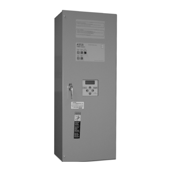
260 amp. size
7000 Series ATS
Refer to the outline and wiring drawings provided
with your 7000 Series ATS for all installation and
connection details and accessories.
Refer to Group 5 Controller User's Guide
381333-126 for ATS status display messages, time
delays, pickup & dropout settings, and adjustments.
Rating Label
Each automatic transfer switch (ATS) has a rating label to
define the loads and fault circuit withstand/closing ratings.
Refer to the label on the transfer switch for specific values.
Do not exceed the values on the rating label.
Exceeding the rating can cause personal injury
or serious equipment damage.
Nameplate
The Transfer Switch nameplate includes data for each
specific ASCO 7000 Series ATS. Use the ATS only within
the limits shown on this nameplate.
An experienced licensed electrician must install the ATS.
TABLE OF CONTENTS
. . . . . . . . . . . . . . . . . . . . . . . .
Mounting and Line Connections
Auxiliary Circuits and Harness
Functional Test
. . . . . . . . . . . . . .
. . . . . . . . . . . . . . . . . . . . . . . . . .
. . . . . . . . . . . . . . . . . . . . . .
. . . . . . . . . . . . . . . . . . . . . . . . .
www.asco.ca
section-page
1-1
. . . . . . . . .
1-1
. . . . . . . . . . .
1-2
. . . . . . . . . . . . . . .
1-2
1-2 through 1-5
. . . . . . . . . . . . . . . . . .
2-1
2-1
. . . . . . . . . . . . . . . .
2-1
. . . . . . . . . . . .
2-1
. . . . . . . . . . . . . . . . . .
2-2
2-2
back cover
381333-283 B
Advertisement
Table of Contents

Related Manuals for Asco 7000 Series


Summary of Contents for Asco 7000 Series
-
Page 1: Table Of Contents
381333–283 B For sales or service call 1 800 800–2726 (ASCO) www.ascopower.com ASCO POWER TECHNOLOGIES CANADA PO Box 1238, 17 Airport Road, Brantford, Ontario, Canada N3T 5T3 telephone 519 758–8450, fax 519 758–0876, for service call 1 888 234–2726 (ASCO) - Page 2 Catalog Number Identification A typical Catalog Number is shown below with its elements explained. The example is for a 7000 Series 7ATS with overlapping neutral, 3 pole, 600 amp, 480 V, in a Type 1 enclosure: 7ATS design prefix letter...
- Page 3 Selector switch for automatic/manual retransfer to 73AC3 Load side protection. (3Ø, 4wire WYE) normal. Automatic bypass if emergency fails. Note: Other distribution voltages available (Contact ASCO). Special Applications Indicators Custom Alphanumeric nameplate mounted on the front 14A/14B Additional auxiliary contact sets to indicate switch of the switch position.
-
Page 4: Installation
SECTION 1 INSTALLATION ASCO 7000 Series Automatic Transfer Switches (ATSs) Testing Power Conductors are factory wired and tested. Field installation requires Do not connect the power conductors to the transfer requires mounting and connection of service cables, switch until they are tested. Installing power cables in and auxiliary control circuits (if required). -
Page 5: Engine Starting Contacts
INSTALLATION (continued) Engine Starting Contacts All customer connections, including the engine control contact connections, are located on terminal block TB which is mounted on the top right side of the enclosure. Refer to the wiring diagram provided with the automatic transfer switch and connect the engine start wires to the appropriate terminals. - Page 6 INSTALLATION (continued) 1 – Manual Operation Test left side of A detachable maintenance handle is provided on the transfer switch frame of the Transfer Switch for maintenance purposes only. Manual operation of the transfer switch should be checked before it is energized (operated electrically). Do not manually operate the transfer switch until both power sources are disconnected: maintenance...
- Page 7 INSTALLATION (continued) GREEN observe these lights GREEN Figure 1-4. Standard controls and indicators. Close the normal source circuit breaker. The Transfer Switch 2 – Voltage Checks Connected To Normal and the First check nameplate on transfer switch; rated voltage Normal Source Accepted lights should come on.
- Page 8 INSTALLATION (continued) operate GREEN this switch observe these lights GREEN Figure 1-5. Standard controls and indicators. 3 – Electrical Operation The Transfer Switch Connected To Normal and Normal Source This procedure will check the electrical operation of Accepted lights should be on. the Automatic Transfer Switch.
-
Page 9: Testing & Service
TESTING & SERVICE TRANSFER TEST DISCONNECTING THE CONTROLLER Operate the 7000 Series ATS at least once a month by The harness disconnect plugs are furnished for repair following the five–step Electrical Operation Transfer purposes only and should not have to be unplugged. If Test procedure on page 1–5. -
Page 10: Manual Load Transfer
* These are factory settings. Refer to the Group 5 Controller User’s Guide. If the problem is isolated to circuits on the controller or the transfer switch, call your local ASCO Power Technologies sales office or ASI. In the United States, call 1–800–800–2726. In Canada, call 1–800–234–2726. -
Page 11: Index
1–3 voltage checks, 1–4 optional accessories voltage, pickup and dropout settings see Controller User’s Guide harness, 1–1 see Controller User’s Guide disconnect plugs, 2–1 HELP 800–800–2726 (ASCO) customercare@asco.com Printed in U.S.A. Copyright --- ASCO Power Technologies, L.P . 2007...
Need help?
Do you have a question about the 7000 Series and is the answer not in the manual?
Questions and answers