Table of Contents
Advertisement
Quick Links
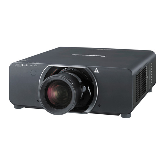
The projection lens is sold separately.
3-chip DLP Based Projector
PT-DZ13KU
Model No.
PT-DZ13KE
PT-DS12KU
PT-DS12KE
PT-DW11KU
PT-DW11KE
PT-DZ10KU
PT-DZ10KE
Replacement lamp unit
■
ET-LAD310A (1 pc)
ET-LAD310AW (2 pcs)
Replacement filter unit
■
ET-EMF320
Replacement lamp unit
■
(for portrait mode)
ET‑LAD320P (1 pc)
ET‑LAD320PW (2 pcs)
© Panasonic Corporation 2013. Unauthorized
copying and distribution is a violation of law.
ORDER NO. VED1304464CE
D10
Rev._2 2013-05
Advertisement
Chapters
Table of Contents

Related Manuals for Panasonic PT-DZ13KU


Summary of Contents for Panasonic PT-DZ13KU
- Page 1 ■ ET-LAD310A (1 pc) ET-LAD310AW (2 pcs) Replacement filter unit ■ ET-EMF320 Replacement lamp unit ■ (for portrait mode) ET‑LAD320P (1 pc) ET‑LAD320PW (2 pcs) © Panasonic Corporation 2013. Unauthorized copying and distribution is a violation of law. Rev._2 2013-05...
- Page 2 IMPORTANT SAFETY NOTICE There are special parts used in Panasonic LCD Projectors which are important for safety. These parts are shaded on the schematic diagram. It is essential that these critical parts should be replaced with manufacturer’s specified parts to prevent shock, fire, or other hazards.
- Page 3 Cautions when transporting ■ ・The projection lens (optional) is susceptible to effects due to vibration or impact. Make sure to remove the lens when transporting. ・When transporting the projector, hold it securely by its bottom and avoid excessive vibration and impacts. They may damage the internal components and result in malfunctions.
-
Page 4: Table Of Contents
CONTENTS COVER PAGE ■ 1. Safety Precautions 2. Specifications SECTION 1 <Service Information> ■ 1. The name of each part 2. Menu Navigation 3. Service Mode 4. External Controls 5. Notification for service operation 6. Troubleshooting ■ SECTION 2 <Disassembly Procedures> 1. -
Page 5: Safety Precautions
1. Safety Precautions 1.1. General Guidelines - For continued safety, no modification of any circuit must be attempted. - Unplug the power cord from the power outlet before disassembling this projector. - Use correctly the supplied power cord and must ground it. - It is advisable to use an isolation transformer in the AC power line before the service. -
Page 6: Specifications
2. Specifications 2. 1. Specifications ・The specifications of the projector are as follows. - Page 7 2. 2. Applicable scanning frequency ・Refer to operating instructions “List of compatible signals” for the types of video signals that can be used with the projector.
- Page 8 2. 3. Terminal...
- Page 10 SECT I ON 1 Service Information PT-DZ13KU / DZ13KE Model No. PT-DS12KU / DS12KE PT-DW11KU / DW11KE PT-DZ10KU / DZ10KE CONTENTS ・・・・・・・・・・・・・・・・・・・・・・・・・・・・・・・・・・・・・・・・・・・・・・・・・・・ 1. The name of each part INF-2 1. 1. Projector body 1. 2. Control panel 1. 3. Connecting terminals 1.
-
Page 11: The Name Of Each Part
1. The name of each part 1. 1. Projector body ■ Front Rear ■ ■ Bottom ■ INF - 2... - Page 12 1. 2. Control panel 1. 3. Connecting terminals INF - 3...
- Page 13 1. 4. Remote control Front ■ ■ ■ Bottom ■ INF - 4...
-
Page 14: Menu Navigation
2. Menu Navigation INF - 5... - Page 15 INF - 6...
- Page 16 INF - 7...
- Page 17 INF - 8...
-
Page 18: Service Mode
3. Service Mode This projector has Service Mode in addition to standard on-screen menus (User Mode). This mode enables some menu settings for the service operation. 3. 1. Setting to Service Mode 1. Please push the main body or the menu (MENU) button of the wireless remote controller. 2. - Page 19 5. SELF CHECK Self-diagnosing information Displays. SELF CHECK * If any error occurs, font of "OK" becomes red. Main microprocessor Software Version Sub microprocessor Software Version Network microprocessor Software Version rootfs/kernel Ballast microprocessor Software Version Intake air temperature check (Celsius/Fahrenheit) DMD temperature check (Celsius/Fahrenheit) Exhaust air temperature check (Celsius/Fahrenheit) Airflow sensor check (Sensor value/AD conversion value/Correction value)
- Page 20 10. CLOG SENSOR CALIBRATION Calibrate the clogging sensor circuit. * Execute this after EEPROM IC3509/IC3518 /A-P.C.Board or clogging sensor (M2-P.C.Board) is replaced. * Please refer to Clause 1 of SECTION 3 (Adjustments) for the procedure. 3. 3. 2. Additional function of each menu 1.
- Page 21 - LAMP1 Lamp1 fan status [Rotational speed] - LAMP2 Lamp2 fan status [Rotational speed] - P-UNIT Power fan status [Rotational speed] - BALLAST Ballast fan status [Rotational speed] - C-MIRROR Composition mirror fan status [Rotational speed] - DMD-EXST DMD exhaust fan status [Rotational speed] - C-PRISM Color prism fan status [Rotational speed] - DMD1...
-
Page 22: External Controls
4. External Controls 4. 1. Control through Serial terminal SERIAL terminals which are on the side of the projector conform to RS-232C standard. This projector can be controlled by a PC which is connected as shown below. Also SERIAL OUT terminal is provided to enable plural projector control. 4. - Page 23 4. 1. 6. Basic format Transmission from the computer starts with STX, then the ID, command, parameter, and ETX are sent in this order. Add parameters according to the details of control. 1. Basic control command (without parameter) Start Separator D...
- Page 24 3. Generate a 32-byte hash value from the following data using MD5 algorithm. xxxxxx Administrator rights user name for Web control (default user name is “admin1”) Password of above administrator rights user (default password is “panasonic”) 8-byte random number obtained in Step 2) : colon : Separator...
- Page 25 2. Receives a response Response = "NTCONTROL 1 1aa6c14e" + (CR) "1aa6c14e" = 8 bytes random characters 3. Generates a hash value (message digest) from "admin1:panasonic:1aa6c14e" by using the MD5 algorism. "admin1" = Administrator authority user-name "panasonic" = Password corresponding to "admin1"...
- Page 26 4. 2. 3. When Web control administrator rights password is not set (Non-protect mode) 4. 2. 3. 1. Connecting 1. Obtain the IP address and port number (Initial setting value = 1024) of the projector and request for a connection to the projector.
- Page 27 ・Panasonic takes no responsibility for any damage or malfunction of the product Notes resulting from use of lamp units which are not manufactured by Panasonic. Use only specified lamp units. ・For the portrait setting, be sure to use the optional Replacement lamp unit (for portrait mode).
- Page 28 5. 1. 4. Lithium battery 1. The lithium battery is used for the internal clock in the A-P.C.Board. So when it consumed it must be replaced. * Use only specified lithium battery. Lithium battery : CR2032 * Used battery must be scrapped according to the instruction. 2.
- Page 29 5. 2. 4. Replacement of A-P.C. board When the replacement of A-P.C.Board (assembly) is needed, back up the memory information such as adjustment data from the old board to PC with the service soft. Then transfer this data to the new A-P.C.Board. For more information refer to the SECTION 3 "Adjustment".
- Page 30 5. 3. 3. Notes on the replacement of the lamp unit 1. Since the luminous lamp is made of glass, it may burst if dropped or hit with a hard object. Handle with care. 2. When replacing the lamp unit, be sure to hold it by the handle because its surface is pointed and its shape is protruded. 3.
- Page 31 5. 3. 5. Air filter maintenance 1. Air filter is clogged by dust, and if the replacement message is displayed on the screen, filter indicator <FILTER> has a red light. In this case perform the maintenance. 2. The proceeds of the air filter clogging, becomes hot of projector inside, and <TEMP>indicator is lit , power shut down. Then <FILTER>Indicator remains red , <TEMP>...
- Page 32 5. 5. Portrait Mode When using the projector in the portrait mode (projection of vertically long images). 1. Install the optional Replacement lamp unit (for portrait mode) to the projector. Replacement lamp unit (for portrait mode) : ET-LAD320P (1 pc)/ ET-LAD320PW (2 pcs) 2.
-
Page 33: Troubleshooting
6. Troubleshooting 6. 1. Shutdown system When something wrong such as stop of fan happens, the projector has a function to be on standby immediately. Indicator indication Shutdown detection Probable cause OSD warning, etc Power fuse Blown out of the fuse ⇒20A (U nodel) ( with some reason ) ⇒10A (E model) - Page 34 6. 2. System log data acquisition method 6. 2. 1. Equipment to be used 1. Computer : Use it for the collect of log data. 2. Communication cable : D-sub 9pin (male/female RS-232C straight) 3. Service Software : [DataLogBackup.exe] Service software is downloaded from the projector service homepage. 6.
- Page 35 5. Select "Log (SYSTEM)" and click "Get" button 6. Log is displayed. INF - 26...
- Page 36 6. 2. 4. Error cord of system log Error code hex Factor Description 00000000 00000001 Intake air temperature warning 00000000 00000002 Optical module high temperature warning The temperature inside this projector has become 00000000 00000004 Exhaust air high temperature warning high or ambient temperature is too low.
- Page 37 20000000 00000000 Unused 40000000 00000000 Unused 80000000 00000000 Unused 00000000 00000001 Portrait lamp warning Portrait mode only lamp is not in use. 00000000 00000002 Unused 00000000 00000004 Unused 00000000 00000008 Dynamic iris error Iris abnormal operation. 00000000 00000010 Unused 00000000 00000020 Unused 00000000 00000040 Unused...
- Page 38 6. 3. Troubleshooting * The letters in the left of inspection items indicate the P.C. Boards related to their respective descriptions. * Inspection should be done with the rear cover attached. (R31 connector = inter lock detection) ■ Power does not turn ON. (Power indicator does not light in red.) Confirm the connection of each connector.
- Page 39 ■ Lamp does not turn ON. (Lamp1 and Lamp2 indicator blink 3 times) *The decline of AC voltage or instant blackout makes the lamp turned off. Confirm the situation of power supply. * After turning off the lamp, the temperature of the lamp is high. Turn the power supply on when the temperature of the lamp is low. Check the status of each lamp unit.
- Page 40 ■ No image appears (picture is abnormal) Check that all the cables are connected properly. Connect the cables properly. Check the input signal. (other than all black picture) No picture appears during VIDEO input. Follow the section "VIDEO input checks". No picture appears during Y/C input.
- Page 41 ● VIDEO input checks Check the picture condition Y/C, RGB1, RGB2, HDMI input. Follow the section "A-P.C.Board operation checks". If all four pictures are abnormal, go to NG. Check and repair FL3001,IC3062 and peripheral Check the waveform at C3013. circuits. Check and repair IC3501, X3501 and the peripheral circuits.
- Page 42 Check the waveform at R3478(G9), R3444(CLK), Follow the section "A-P.C.Board operation checks". R3484(HS,VS). Check the waveform at R3169(G9), R3174(CLK), Check and repair IC3010 and the peripheral circuits. R3173(HS,VS). Check and repair IC3058 and the peripheral circuits. ● RGB2 input checks Check the picture condition VIDEO, RGB1, Y/C, HDMI input.
- Page 43 ● DVI-D input checks Check the picture of SDI2 input. Or select the "P in P" (main RGB1 (no input) and sub RGB2), check the picture of RGB2. Check the waveform on R3259(AE_ACT). Check circuits between JK3005 and IC3020. Check and repair R3493(ACT), IC3058 and the peripheral circuits.
- Page 44 ● SDI1 input checks (DZ13K/DS12K/DZ10K only) Check the voltage on the power lines. Check and repair IC3059,IC3401 and the peripheral IC3059 1pin : Approx 3.3V circuits. IC3401 1pin : Approx 1.2V Voltage on IC3072 7pin is 0.4 V or less. Check and repair IC3071 and the peripheral circuits.
- Page 45 ● PinP of RGB1/RGB2 input checks Turn off a PinP mode. Follow the section "RGB1 input checks". Check the picture condition RGB1, RGB2 input. Follow the section "RGB2 input checks". Check the waveform at Follow the section "A-P.C.Board operation checks". R3487(G9),R3446(CLK),R3493(HS,VS).
- Page 46 ● Main CPU operation checks * CPU : Central Processing Unit Check the clock waveform. Check and repair X3402 and the peripheral circuits. R3575 : 35.455MHz Check and Replace cable between connectors P21 and The voltage of G10 connector. G10. 2pin : 3.3V, 6pin : 5V Replace the P-P.C.Board.
- Page 47 ■ SERIAL IN/OUT does not respond Check RS-232C cable connection. (JK6003/JK6004) Connect the cables properly. When the command is transmitted, the signal can Check and repair IC6011 and the peripheral circuits. be detected at 10,12,17 pins of IC6010. Replace the G-P.C.Board. ■...
- Page 48 SECT I ON 2 Disassembly Procedures PT-DZ13KU / DZ13KE Model No. PT-DS12KU / DS12KE PT-DW11KU / DW11KE PT-DZ10KU / DZ10KE CONTENTS 1. Parts Location ・・・・・・・・・・・・・・・・・・・・・・・・・・・・・・・・・・・・・・・・・・・・・・・・・・・・・・・・・・・・・・・・ DIS-2 1. 1. Electrical Parts Location (P.C.Board) 1. 2. Electrical Parts Location (Fan) 1. 3. Mechanism element parts location 2.
-
Page 49: Electrical Parts Location (P.c.board)
1. Parts Location 1. 1. Electrical parts location (P.C.Board) BQ(Lamp2) BQ(Lamp1) M1(Ext) FG(B) FR(R) FG(G) M1(Int) Function summary Function summary Board Name Board Name A Image processing system / CPU Relay Board (A-WF) Control terminal / Fan,Iris,Motor Drive Front IR Receiver / Status LED W... -
Page 50: Mechanism Element Parts Location
1. 3. Mechanism element parts location Upper Case Engine Block Case(Top) DMD Block Synthesis Block Rear Cover Analysis Block Signal Processing Block Analysis Mirror Power Supply Block Ballast Block Intake Duct Air Filter Lens Mount (Assy) Bottom Cover DIS-3... -
Page 51: Disassembly Instructions ・・・・・・・・・・・・・・・・・・・・・・・・・・・・・・・・・・・・・・・・・・・・・・・・・・・・・・・ Dis-4
2. Disassembly Instructions 2. 1. Flowchart for Disassembly * Before Disassembly the projector, turn off the POWER switch and disconnect the power plug from the wall outlet. * To assemble, reverse the disassembly procedures. * When tore off sticky tapes, please use a new thing without reusing it on the occasion of assembling. Completed Product 2. - Page 52 2. 2. Removal of Lamp Unit 1. Loosen the 1 screw until it idles, then remove the Rear cover (Assy). Rear cover (Assy) 2. Loosen the 2 screws until they idle, hold the handles and pull the lamp unit out from the main unit. Lamp unit 2 Lamp unit 1 2.
-
Page 53: Removal Of Intake Duct (Assy)
3. Unscrew the 8 screws and remove the upper case. XSB4+10FJK XSB4+10FJK R-P.C.Board RM-P.C.Board F-P.C.Board XTW3+8PFJ M2-P.C.Board XYN3+F8FJ Unscrew the 2 screws and remove the R-P.C.Board. Unscrew the 2 screws and remove the RM-P.C.Board. Unscrew the 2 screws and remove the RL-P.C.Board. Unscrew the 1 screw and remove the M2-P.C.Board. -
Page 54: Removal Of Engine Block Case (Top)/Dmd Block
2. 5. Removal of Engine Block Case (Top)/DMD Block 1. Remove the Intake Duct (Assy) according to the section 2.4. "Removal of Intake Duct (Assy) / ACF(Assy)". 2. Unscrew the 3 screws and remove the Engine Block Case (Top). RL-P.C.Board * Depending on the position of the focus, Engine Block Case (Top) there is the case that is hard to come off. -
Page 55: Removal Of Analysis Block/Synthesis Block/Synthetic Mirror
2. 6. Removal of Analysis Block/Synthesis Block/Synthetic Mirror 1. Remove the Lamp Unit according to the section 2.2. "Removal of Lamp Unit". 2. Remove the Engine Block Case (Top) according to the section 2.5. "Removal of Engine Block Case (Top) / DMD Block". 3. -
Page 56: Removal Of Rod(Assy)/Iris Unit (Assy)/Relay Lens
6. Unscrew the 4 screws, and divide Analysis Block and Synthetic Block. XYN4+J12FJ Synthetic Block (lamp case side) ・Unscrew the 3 screws and remove the each synthetic Mirror. XYN3+F8FN Lamp Fan Lamp Fan XYN3+F8FN Synthetic Mirror 2. 7. Removal of Rod (Assy)/Iris Unit (Assy)/Relay Lens 1. - Page 57 4. Unscrew the 4 screws and remove the Analysis Case (Top). Analysis Case (Top) * Analysis case assembling needs the confirmation of the lighting area afterward. Please refer to the SECTION3 adjustments. XYN3+F8FJ ・Unscrew the 2 screws and remove the Iris Unit (Assy). ・Unscrew the 2 hexagon socket head screw and remove the Relay Lens holder.
-
Page 58: Removal Of Analysis Mirror (Assy)
2. 8. Removal of Analysis Mirror (Assy) 1. Remove the Analysis Block according to the steps 1 through 5 in the section 2.6. "Removal of Analysis Block / Synthesis Block / Synthetic Mirror". 2. Unscrew the 4 screws and remove the DMD Block. XYN3+F12FJK DMD Block ・Unscrew the 4 screws and remove the Analysis Mirror (Assy). -
Page 59: Removal Of Signal Processing Block (A/G/Wf/Wl-P.c.board)
2.10. Removal of Signal Processing Block (A/G/WF/WL-P.C.Board) 1. Remove the Terminal Cover according to the section 2.9. "Removal of Terminal Cover". 2. Unscrew the 4 screws and remove the Signal Processing Block. XYN3+F8FJ Signal Processing Block ・Unscrew the 3 screws and remove the WF-P.C.Board. B to B connector (RW-P.C.B) WF-P.C.Board XYN3+F8FJ... -
Page 60: Removal Of Ballast Block (B/Q-P.c.board)
4. Unscrew the 17 screws and remove the Terminal Plate. Terminal Plate THEC084N XYN3+F8FJ XYN3+F8FJ XYN26+C6FJ XTB3+8JFJ XQN2+B5FJ ・Unscrew the 5 screws and remove the A-P.C.Board. XYN3+F8FJ A-P.C.Board 2.11. Removal of Ballast Block (B/Q-P.C.Board) 1. Remove the Lamp Cable Socket (two places) according to the steps 1 through 4 in the section 2.6. "Removal of Analysis Block / Synthesis Block / Synthetic Mirror". -
Page 61: Removal Of Power Supply Block (P-P.c.board)
4. 1) Unscrew the 2 screws and remove the Ballast Fan. 2) Unscrew the 4 screws and remove the Support plate, Ballast mesh. 3) Unscrew the 4 screws, separate the Ballast case 1 and Ballast case 2. XYN3+F6FJK Support plate XYN3+F30FJK Ballast case 1 XYN3+F6FJK... -
Page 62: Removal Of Lens Mount (Assy)
・Unscrew the 7 screws and remove the PC-P.C.Board. XYN3+F8FJ P-P.C.Board 2.13. Removal of Lens Mount (Assy) 1. Remove the Analysis Mirror (Assy) according to the section 2.8. "Removal of Analysis Mirror (Assy)". 2. Remove the Signal Processing Block according to the steps 1 through 3 in the section 2.10. "Removal of Signal Processing Block". -
Page 63: Bottom Case
3. Wiring 3. 1. Bottom case *Clamp *M11-RL10 lead wire is through the inside of bottom case protrusion. *Lead wire is passed through the notch portion of power shield case Composition Mirror Fan *Clamp ・M11-RL10 lead wire ・Composition Mirror Fan Power supply block lead wire *Lead wire (P12-BIMETAL) hang it on... -
Page 64: Dmd Block
3. 3. DMD block *FM Power lead wire (FG1/FG1/FR1-Relay connector *FFC(FG2-WF3) FG1(Blue) *FFC(FG2-WF5) FG1(Black) *FFC(FR2-WF4) *Each flexible cable is tuck down on the downside. *WF4-FR2 flexible cable is through between the absorber bracket. *Clamp ・DMD1 fan-G5 lead wire ・DMD temperature sensor-G14 lead wire ・FM Power lead wire The tip of a clamp is turned to... -
Page 65: Signal Processing Block
3. 4. Signal processing block *DMD2 fan-R2 lead wire is outside of the signal processing block case. *DMD2 fan-R2 and Color prism fan-G7 lead wire is untack (take up the slack) from inside of the Engine block case. *That the FM power lead wire and flexible cables do not overlap. -
Page 66: Rl-P.c.board
3. 6. RL-P.C.Board RL14 RL10 RL6 RL13 RL5 RL12 *The lead wires lets the inside of the line processing sheet go through. *Clamp ・RL3-Intake2 fan lead wire ・RL5-Lamp2 fan lead wire ・RL6-Composition mirror fan lead wire ・RL8-F1 lead wire ・RL9-M21(Air flow sensor) lead wire ・RL10-M11(Intake temperature sensor) lead wire ・RL12-L21(Lamp2 memory) lead wire ・RL13-H1/MR1(Iris) lead wire... - Page 67 SECT I ON 3 Adjustments PT-DZ13KU / DZ13KE Model No. PT-DS12KU / DS12KE PT-DW11KU / DW11KE PT-DZ10KU / DZ10KE CONTENTS 1. Adjustment items and procedure ・・・・・・・・・・・・・・・・・・・・・・・・・・・・・・・・・・・・・・・・・ ADJ-2 1. 1. Lighting area adjustment 1. 2. Electrical convergence adjustment 1. 3. Lens calibration 1.
-
Page 68: Lighting Area Adjustment
1. Adjustment item and a procedure When the following components in this projector are replaced, adjustments are required. Adjust each item according to the table below. Adjustment Item Replaced Component Remarks 1.1. Lighting Area Adjustment DMD Block / Each Analysis Block part 1.2. -
Page 69: Electrical Convergence Adjustment
1. 2. Electrical Convergence Adjustment It is a function to correct a convergence by a pixel unit every R/G/B ingredient. ・When adjust the DZ/DS models, because it uses the entire pixel of DMD, the edge pixel of the projection Note screen is missing. -
Page 70: Eeprom Data Transfer
1. 4. EEPROM data transfer 1. 4. 1. Equipment to be used 1. Computer : Use it for the transfer of backup data. 2. Communication cable : D-sub 9pin (male/female RS-232C straight) 3. Service Software : [DataLogBackup.exe] Service software is downloaded from the projector service homepage. 1. - Page 71 5. 1) Select "Backup (EEPROM)”. 2) Checkmark in "REPLACE A-PWB" of "COPY MODE". 3) Click an [READ EEPROM] button. 6. Select the save place and click the [Save(S)] button. 7. When the progress bar reaches the right-side end, the read of data is completion. Select "File"...
- Page 72 1. 4. 4. Restore the backup EEPROM Data (After circuit board exchange) 1. Switch the projector to "Normal-Standby" mode (POWER indicator is Lighting in red). 2. Start up service software [DataLogBackup.exe] with a computer. 3. Select "Option " ⇒ " Setting" and set Serial Port of the computer, Baud Rate and Parity. 4.
-
Page 73: Model Information Setup
1. 5. Model Information Setup 1. Setting to service mode and select sub menu "MODEL" of main menu "EXTRA OPTION". 2. Select a model and push the “ENTER” button. 3. When to turn off the main power and turned on again, the setting is complete. 1. -
Page 74: Contrast Adjustment
1. 7. Contrast adjustment 1. 7. 1. Equipment to be used 1. Luminance meter : Konica Minolta T-10 or CL-200 2. Projection lens : ET-D75LE20 3. Adjust it in a darkroom. 1. 7. 2. Set up the projector 1. Setting to service mode. 2. - Page 75 2. Software Update procedure * LAN terminal connection, be able to update the Maine, Sub, Network microprocessor software. * Serial terminal connection, be able to update Maine, Sub microprocessor software. 2. 1. Update by the LAN terminal connection (Main/Sub/Network) 2. 1. 1. Equipment to be used 1.
- Page 76 5. Select Microprocessor to update, and click [load] button. 6. Appoint the microcomputer software that took in a computer beforehand, and click [Open] button. 7. When load of the microcomputer software is completed, a checkmark and path and a version are displayed. * When do not do update in Microprocessor Software which did load, exclude a checkmark of Microprocessor to fall under.
- Page 77 8. Click [OK] button and start update. While update it, Lamp1-2 indicator indicates as follows. *Main:Lamp indicator 1-2, alternately flashing red. *Sub:Lamp indicator all lit red. *Network:Lamp indicator 1-2, alternately flashing red. 9. If completion and a message are displayed, click [OK] button. *Rewrite the same version of software will be skipped.
- Page 78 2. 2. Update by the SERIAL terminal connection (Main/Sub/Formatter) 2. 2. 1. Equipment to be used 1. Computer : Use it for the transfer of software. 2. Communication cable : D-sub 9pin (male/female RS-232C straight) 3. Service Software : [MainSubNet Update Tool.exe] Service software is downloaded from the projector service homepage. 4.
- Page 79 5. Select Microprocessor to update, and click [load] button. *Update of the network software by serial terminal connection is not possible. 6. Appoint the microcomputer software that took in a computer beforehand, and click [Open] button. 7. When load of the microcomputer software is completed, a checkmark and path and a version are displayed. * When do not do update in Microprocessor Software which did load, exclude a checkmark of Microprocessor to fall under.
- Page 80 8. Click [OK] button and start update. While update it, Lamp1-2 indicator indicates as follows. *Main:Lamp indicator 1-2, alternately flashing red. *Sub:Lamp indicator all lit red. 9. If completion and a message are displayed, click [OK] button. *Rewrite the same version of software will be skipped.
- Page 81 SECT I ON 4 Schematic Diagram Important Safety Notice Components identified by the international symbol have special characteristics important for safety. PT-DZ13KU / DZ13KE Model No. When replacing any of these components, use only the manufacturer's specified ones. PT-DS12KU / DS12KE ■Notes PT-DW11KU / DW11KE 1.
- Page 82 1. Block Diagram 1. 1. Power Supply and Ballast B/Q-P.C.B(1) Q-P.C.B UART TXD PHOTO- UART RXD ISOLATOR LAMP ON PC9501~4 SYNC IC9801 COLD AC INLET B-P.C.B POWER AC SW D001 Q101.Q107 CODE K001 F001 F101 Q9611 Q9615 F9601 380V LINE 380V RECTIFIER LAMP1...
- Page 83 1. Block Diagram 1. 2. Control and Driving System DMD2 FAN P-UNIT FAN FOCUS MORTOR V_SHIFT MOTOR ZOOM MOTOR POSITION SWITCH H_SHIFT MOTOR S-P.C.Board DATA SERIAL IN PARALLE OUT DRIVER FRONT RM-P.C.B IC100 R-P.C.B DMD-EXHAUST FAN DMD1 FAN BALLAST FAN C-PRISM FAN IC6507 IC6508...
- Page 84 1. Block Diagram 1. 3. Signal Processing A-P.C.B DZ13K/DS12K/DZ10K Only IC3072 IC3501 CABLE IC3508 SDI IN 1 EQUALIZER 128M FLASH MEMORY IC3071 IC3502 IC3513 CABLE SDI IN 2 DDR3 EQUALIZER SDRAM 64M SDRAM IC3503 DZ13K/DS12K Only WF-P.C.B IC3062 DDR3 3.3V 3.3V 1.8V 1.2V_WL...
- Page 85 REMOTE 2 REMOTE 1 REMOTE 1 SERIAL OUT SERIAL IN 3D SYNC RGB1 RGB2 * DZ13K/DS12K/DZ10K only 2. Interconnection Block Diagram R1-P.C.B DMD-2 FAN JK3005 JK3007 JK3003 JK3002 JK3001 JK2001 POWER FAN VIDEO JK3004 DMD EXHAUST FAN F_B- R2-P.C.B F_A+ F_B+ S-P.C.B COLOR PRISM FAN...
- Page 86 +12VB L3007 G1C100K00031 3. Schematic Diagram R300336 R3024 113 J0JHC0000078 IC3058 FPGA1 L3401 C3417 C3414 C3432 1.2V VCCINT VCCAUX J0JJC0000022 G1C2R2ZA0240 6.3V 6.3V 220u 2V J0JJC0000022 L3006 3.3V L3400 R3425 C3423 L3404 C3464 R3004 36 R3025 113 3.3k 1000p 7.3X4.3 C3460 C3435 C3434...
- Page 87 +3.3V_A1_REG +3.3V_B +3.3V_B +3.3V_B +1.2V_SCX2 +3.3V_B +3.3VSTB +1.2V_SCX2 +1.5V_DDR3 R3533 R3539 L3523 J0JJC0000022 3. Schematic Diagram C3819 C3811 0.1u 3. 1. A-P.C.Board (2/3) C3758 +3.3V_BVCC L3504 L3516 L3512 J0JJC0000022 IC3501 ANTHREFIN J0JJC0000022 J0JJC0000022 C3757 C3808 C3536 C3569 C3588 J0JJC0000022 L3519 C3614 RLD_VTT.75V IC3501...
- Page 88 3. Schematic Diagram 3. 1. A-P.C.Board (3/3) +5VSTB NT+5VSTB L2001 J0JHC0000107 +3.3VSTB IC2004 TP2023 Q2001 IC2005 B1CHRC000024 R2213 NT_RST <-- RST# LAN_RESET (SUB CPU) C2035 C2037 0.1u C2036 R2253 NT_GIO5 R2094 0.22u <-- LAN_GIO5 (MAIN CPU) C0EBE0000348 R2204 NT_PWREN --> POWER DELAY C0JBAU000084 LAN_PWREN...
- Page 89 3. Schematic Diagram R8_REMOTE2D R8_REMOTE2C 3. 2. G-P.C.Board (1/2) 1.55- min=5.3V L6022 J0JCC0000168 max=5.76V ZA6001 ZA6002 ZA6003 ZA6004 ZA6005 K4CD01000013 K4CD01000013 K4CD01000013 K4CD01000013 K4CD01000013 C6062 IC6011 0.1u L6025 J0JCC0000168 ECO STB CONTROL PANEL FL6001 C0JBAZ001633 +3.3VECO F1J1E1040022 R6124 K1KA06A00508 /OE1 SUB CPU CURCUIT /OE2 L6001...
- Page 90 3. Schematic Diagram 3. 2. G-P.C.Board (2/2) DMD EXHAUST FAN DMD FAN1 POWER FAN PRISUM FAN BALLAST FAN MAX300mA MAX500mA MAX200mA EXST_L FAN IC6501 MAX300mA +3.3VSTB ZOOM/SHUTTER +18V C0DBAYY00397 L6501 IC6508 IC6510 IC6511 IC6513 +12VB +2.5V G1C100MA0291 IC6507 C0CBCYG00004 C0CBCYG00004 C0CBCYG00004 C0CBCYG00004 D6512...
- Page 91 3. Schematic Diagram 3. 3. S-P.C.Board L-STB3.3V2 L-STNBY3.3V L-STB3.3V FL9953 J0HAAB000036 C9950 KEYSCAN1 0.1u R9950 R9957 R9964 5.6k KEYSCAN2 5.6k 5.6k KEY1 KEYSCAN3 FL9952 HDMI POWER ON J0HAAB000036 SW9956 SW9950 SW9961 L9950 J0JCC0000168 R9951 R9965 EVQ11G05R EVQ11G05R EVQ11G05R R9958 1.5k 1.5k 1.5k K1KA06A00508...
- Page 92 3. Schematic Diagram 3. 4. F-P.C.Board 3. 5. RM-P.C.Board 3. 6. RL-P.C.Board 3. 7. R-P.C.Board 3. 8. R2-P.C.Board 3. 9. R3-P.C.Board To G-P.C.Board (G13) To ZOOM Motor To FOCUS Motor To V-SHIFT Motor K1KA30B00078 Front IR Receiver K1KA11A00178 F_B- F_A+ +3.3VSTB D1006 S_OUT...
- Page 93 4. Circuit Boards Diagram 4. 1. A-P.C.Board (A-side) ZA3003 C3798 C3799 C3776 C3774 C3772 IC3520 C3821 R3772 ZA3006 C3722 C3724 R3560 R3562 R3774 R3770 R3688 R3692 C3719 C3721 IC3517 R3689 R3693 R3771 C3789 IC3518 R3522 R3759 IC3516 R3773 L3594 C3501 Q3502 Q3501 C3509...
- Page 94 4. Circuit Boards Diagram 4. 1. A-P.C.Board (B-side) C3746 TPA04 L3523 C3771 C3773 C3775 C3747 R3673 T O P TP3009 CL004 CL005 T O P R3502 IC3512 IC3510 R3731 R3730 B t o B C3745 C3743 CL003 CL006 C3706 C3704 CL3501 CL3502 CL3504...
- Page 95 4. Circuit Boards Diagram 4. 2. G-P.C.Board (A-side) ZA6002 ZA6003 R6651 R6649 L6530 L6528 TPG2 TPG1 R6586 TP6530 TP6528 FL6005 CL6003 L6549 L6208 L6207 L6206 L6205 L6204 L6203 L6202 L6201 R6226 R6222 R6219 R6215 R6213 R6209 R6206 R6202 R6225 R6221 R6218 R6214 R6212...
- Page 96 4. Circuit Boards Diagram 4. 2. G-P.C.Board (B-side) L6513 L6509 L6514 L6510 C6625 C6551 C6550 IC6513 R6613 R6557 R6556 C6546 C6616 R6548 R6057 R6059 L6551 R6056 R6058 L6543 L6550 C6563 L6545 R6668 L6546 L6603 L6544 R6667 L6604 L6005 C6702 C6562 L6547 R6619 C6631...
- Page 97 SECT I ON 5 Exploded Views & Parts List PT-DZ13KU / DZ13KE Model No. PT-DS12KU / DS12KE PT-DW11KU / DW11KE PT-DZ10KU / DZ10KE CONTENTS 1. Exploded Views ・・・・・・・・・・・・・・・・・・・・・・・・・・・・・・・・・・・・・・・・・・・・・・・・・・・・・・・・ SPL-2 1. 1. Parts Location 1. 2. Packing Parts ・・・・・・・・・・・・・・・・・・・・・・・・・・・・・・・・・・・・・・・・・・・・・・・・・ 2. Replacement Parts List...
- Page 98 1. Exploaded Views 1.1. Part Location (1/3) WF-P.C.Board S-P.C.Board G-P.C.Board WL-P.C.Board 205 x5 RW-P.C.Board A-P.C.Board BQ-P.C.Board P-P.C.Board SPL-2 SPL-2...
- Page 99 1.1. Part Location (2/3) 217 217 RL-P.C.Board M3-P.C.Board L1-P.C.Board 229 x6 L2-P.C.Board 208 x2 53-8 230 x3 53-9 36-2 52-1 RM-P.C.Board 36-1 53-1 53-3 53-5 MR-P.C.Board 53-7 H-P.C.Board 53-2 53-1 53-4 53-5 53-6 SPL-3...
- Page 100 1.1. Part Location (3/3) 60-3 R3-P.C.Board 60-1 60-2 R2-P.C.Board M1-P.C.Board R-P.C.Board M2-P.C.Board F-P.C.Board M1-P.C.Board SPL-4...
- Page 101 1.2. Packing Parts (U model) 301-1 (E model) 302-1 (E model) 302-1 SPL-5...
- Page 102 <DZ K D K DW K DZ K> 2. Replacement Parts List Ref.No. Part No. Part Name & Description Remarks Ref.No. Part No. Part Name & Description Remarks RELAY LENS 3 TKGF5354-2 MECHANICAL PARTS RELAY LENS 4 TKGF5355 TESA350 LENS HOLD SPRING TBMV340 TERMINAL INDICATION SHEET DZ13K / DS12K...
- Page 103 <DZ K D K DW K DZ K> Ref.No. Part No. Part Name & Description Remarks Ref.No. Part No. Part Name & Description Remarks 76 TKFE18201 BOTTOM CASE XYN3+F12FJK SCREW TBLB3500 ADJUSTER LEG REAR XYN3+F20FJ SCREW ADJUSTER SCREW TBLB3081 XYN3+F30FJK INTAKE DUCT TOP SCREW...
- Page 104 <DZ K D K DW K DZ K> Ref.No. Part No. Part Name & Description Remarks Ref.No. Part No. Part Name & Description Remarks C2011 F1J0J2260004 C.CAPACITOR CH 6.3V 22U ■ A C2012 TXN/99VLF9 CIRCUIT BOARD (A) DZ13K / DS12K series F1G1C104A077 C.CAPACITOR CH 16V 0.1U ...
- Page 105 <DZ K D K DW K DZ K> Ref.No. Part No. Part Name & Description Remarks Ref.No. Part No. Part Name & Description Remarks C3178,79 C3601 CERAMIC 12P J 50V F1J1A106A043 C.CAPACITOR CH 10V 10U F1G1H120A789 C3180,81 C3604,05 C.CAPACITOR CH 10V 10U F1G1A105A047 CERAMIC 1U K 10V F1J1A106A043...
- Page 106 <DZ K D K DW K DZ K> Ref.No. Part No. Part Name & Description Remarks Ref.No. Part No. Part Name & Description Remarks D3066 L3023-26 VARISTOR EMI FILTER D4ED11200005 J0JJC0000022 D3068 VARISTOR L3027-33 EMI FILTER D4ED11200005 J0JYC0000024 D3070,71 DIODE L3034 EMI FILTER B0BC5R600003...
- Page 107 <DZ K D K DW K DZ K> Ref.No. Part No. Part Name & Description Remarks Ref.No. Part No. Part Name & Description Remarks R3032 R3178,79 ERJ3GEYJ331 M 330 OHM,J,1/16W ERJ2GEJ103 M 10K OHM, 0.063W R3033 R3180 ERJ3GEYJ222 M 2.2K OHM,J,1/16W EXB28V330J RESISTOR ARRAY 33 OHM R3034...
- Page 108 <DZ K D K DW K DZ K> Ref.No. Part No. Part Name & Description Remarks Ref.No. Part No. Part Name & Description Remarks R3507 R3694 ERJ2GEJ100 M 10 OHM, 0.063W ERJ2GEJ223 M 22K OHM, 0.063W R3509,10 R3695 ERJ2GEJ100 M 10 OHM, 0.063W ERJ6GEY0R00 M 0 OHM, 1/10W R3511...
- Page 109 <DZ K D K DW K DZ K> Ref.No. Part No. Part Name & Description Remarks Ref.No. Part No. Part Name & Description Remarks C3009 C3435 F1J1C106A059 C.CAPACITOR CH 16V 10U F1J1A106A043 C.CAPACITOR CH 10V 10U C3010 C3436 EEEHP1E220P CAPACITOR F1G1C1030008 C.CAPACITOR CH 16V 0.01U C3011-13...
- Page 110 <DZ K D K DW K DZ K> Ref.No. Part No. Part Name & Description Remarks Ref.No. Part No. Part Name & Description Remarks C3789 IC3511 F1J0J2260004 C.CAPACITOR CH 6.3V 22U C0DBAYY01148 C3790 IC3512 F1G1C104A077 C.CAPACITOR CH 16V 0.1U C0DBAYY00893 C3791 C.CAPACITOR CH 16V 0.01U IC3513...
- Page 111 <DZ K D K DW K DZ K> Ref.No. Part No. Part Name & Description Remarks Ref.No. Part No. Part Name & Description Remarks Q3020-23 R3103 TRANSISTOR RESISTOR B1GBCFJJ0007 ERJ3GEYJ393 Q3025 TRANSISTOR R3104 M 10K OHM, 0.063W B1GDCFJJ0008 ERJ2GEJ103 Q3027,28 TRANSISTOR R3105 M 22K OHM, 0.063W...
- Page 112 <DZ K D K DW K DZ K> Ref.No. Part No. Part Name & Description Remarks Ref.No. Part No. Part Name & Description Remarks R3303 R3599 M 4.7K OHM, 0.063W M 56 OHM, 0.063W ERJ2GEJ472 ERJ2GEJ560 R3304 M 1K OHM, 0.063W R3601-04 M 100 OHM, 1/16W ERJ2GEJ102...
- Page 113 <DZ K D K DW K DZ K> Ref.No. Part No. Part Name & Description Remarks Ref.No. Part No. Part Name & Description Remarks ■ A C3143 TXN/99VLK4 CIRCUIT BOARD (A) DZ10K series F1J1A106A043 C.CAPACITOR CH 10V 10U C3145 F1G1C104A077 C.CAPACITOR CH 16V 0.1U C3147 C.CAPACITOR CH 10V 10U...
- Page 114 <DZ K D K DW K DZ K> Ref.No. Part No. Part Name & Description Remarks Ref.No. Part No. Part Name & Description Remarks C3532 D3018 C.CAPACITOR CH 50V 0.015U DIODE F1H1H153A219 B0JCGD000002 C3533 C.CAPACITOR CH 16V 0.1U D3020-24 DIODE F1G1C104A077 B0JCAE000001 C3534...
- Page 115 <DZ K D K DW K DZ K> Ref.No. Part No. Part Name & Description Remarks Ref.No. Remarks Part Name & Description Part No. L3010 R2253 J0JCC0000168 EMI FILTER ERJ2GE0R00 M 0 OHM, 0.063W L3011 R3001,02 J0JYC0000024 EMI FILTER ERJ3GEYJ102 RESISTOR L3012 EMI FILTER...
- Page 116 <DZ K D K DW K DZ K> Ref.No. Part No. Part Name & Description Remarks Ref.No. Part No. Part Name & Description Remarks R3159,60 R3485-93 ERJ2GEJ220 M 22 OHM, 0.063W EXB28V330J RESISTOR ARRAY 33 OHM R3161,62 R3501-04 ERJ2GEJ103 M 10K OHM, 0.063W ERJ3GEY0R00 M 0 OHM, 1/16W R3163...
- Page 117 <DZ K D K DW K DZ K> Ref.No. Part No. Part Name & Description Remarks Ref.No. Part No. Part Name & Description Remarks R3691 C6036 ERJ3EKF1003 M 100KOHM, 1/16W F1G1H221A571 C.CAPACITOR CH 50V 220P R3692 C6037-41 ERJ3EKF1303 RESISTOR F1G1C104A077 C.CAPACITOR CH 16V 0.1U R3693 RESISTOR...
- Page 118 <DZ K D K DW K DZ K> Ref.No. Part No. Part Name & Description Remarks Ref.No. Part No. Part Name & Description Remarks C6645 IC6002 F2G1E3300010 E.CAPACITOR CH 25V 33U C0EBE0000348 C6647 IC6003 F2G1E4R70007 E.CAPACITOR CH 25V 4.7U C0JBAA000377 C6649-56 C.CAPACITOR CH 16V 0.1U IC6004...
- Page 119 <DZ K D K DW K DZ K> Ref.No. Part No. Part Name & Description Remarks Ref.No. Part No. Part Name & Description Remarks Q6509 R6173 B1CHQD000010 TRANSISTOR EXB28V220J RESISTOR ARRAY 22 OHM Q6510-14 R6174-83 B1ABDF000036 TRANSISTOR ERJ2GEJ220 M 22 OHM, 0.063W R6184-92 M 0 OHM, 1/16W ERJ3GEY0R00...
- Page 120 <DZ K D K DW K DZ K> Ref.No. Part No. Part Name & Description Remarks Ref.No. Part No. Part Name & Description Remarks R6602 R6722 ERJ3GEYJ471 M 470 OHM,J,1/16W EXB28V220J RESISTOR ARRAY 22 OHM R6603 R6723 ERJ3GEYJ271 M 270 OHM,J,1/16W ERJ3GEYJ103 RESISTOR R6604...
- Page 121 <DZ K D K DW K DZ K> Ref.No. Part No. Part Name & Description Remarks Ref.No. Part No. Part Name & Description Remarks RL10 K1KA02AA0104 CONNECTOR RL11 C9950 K1KA04A00667 CONNECTOR F1H1C104A041 C.CAPACITOR CH 16V 0.1U RL12 CONNECTOR K1KA04AA0104 RL13 CONNECTOR FL9950-53 EMI FILTER...
Need help?
Do you have a question about the PT-DZ13KU and is the answer not in the manual?
Questions and answers