Table of Contents
Advertisement
Quick Links
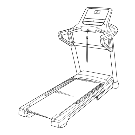
Model No. NETL79019.0
Serial No.
Write the serial number in the space
above for reference.
Serial
Number
Decal
CUSTOMER SERVICE
UNITED KINGDOM
Call: 0330 123 1045
From Ireland: 053 92 36102
Website: iconsupport.eu
E-mail: csuk@iconeurope.com
Write:
ICON Health & Fitness, Ltd.
Unit 4, Westgate Court
Silkwood Park
OSSETT
WF5 9TT
UNITED KINGDOM
AUSTRALIA
Call: 1800 993 770
E-mail: australiacc@iconfitness.com
Write:
ICON Health & Fitness
PO Box 635
WINSTON HILLS NSW 2153
AUSTRALIA
CAUTION
Read all precautions and instruc-
tions in this manual before using
this equipment. Save this manual
for future reference.
USER'S MANUAL
iconeurope.com
Advertisement
Table of Contents

Related Manuals for NordicTrack T7.0 S


Summary of Contents for NordicTrack T7.0 S
- Page 1 Model No. NETL79019.0 Serial No. USER'S MANUAL Write the serial number in the space above for reference. Serial Number Decal CUSTOMER SERVICE UNITED KINGDOM Call: 0330 123 1045 From Ireland: 053 92 36102 Website: iconsupport.eu E-mail: csuk@iconeurope.com Write: ICON Health & Fitness, Ltd. Unit 4, Westgate Court Silkwood Park OSSETT...
-
Page 2: Table Of Contents
305284 NORDICTRACK and IFIT are registered trademarks of ICON Health & Fitness, Inc. App Store is a trademark of Apple Inc., registered in the U.S. and other countries. Android and Google Play are trademarks of Google LLC. -
Page 3: Important Precautions
IMPORTANT PRECAUTIONS WARNING: To reduce the risk of burns, fire, electric shock, or injury to persons, read all important precautions and instructions in this manual and all warnings on your treadmill before using your treadmill. ICON assumes no responsibility for personal injury or property damage sus- tained by or through the use of this product. - Page 4 21. The treadmill is capable of high speeds. frame securely in the storage position. Do Adjust the speed in small increments to not operate the treadmill while it is folded. avoid sudden jumps in speed. 26. Do not change the incline of the treadmill by 22.
-
Page 5: Before You Begin
Thank you for selecting the new NORDICTRACK manual. To help us assist you, note the product model ® T7.0 S treadmill. The T7.0 S treadmill provides an number and serial number before contacting us. The impressive selection of features designed to make your model number and the location of the serial number workouts at home more effective and enjoyable. -
Page 6: Part Identification Chart
PART IDENTIFICATION CHART Use the drawings below to identify small parts used for assembly. The number in parentheses below each draw- ing is the key number of the part, from the PART LIST near the end of this manual. The number following the key number is the quantity used for assembly. -
Page 7: Assembly
ASSEMBLY • Assembly requires two persons. • Left parts are marked “L” or “Left” and right parts are marked “R” or “Right.” • Place all parts in a cleared area and remove the packing materials. Do not dispose of the packing •... - Page 8 3. Lay the Right Upright (90) near the Base (94). Press the Grommet (77) into the square hole (B) in the Right Upright. Make sure not to pinch the ground wire (C). If there is a screw (D) preattached to the Right Upright (90), remove and discard it.
- Page 9 5. Remove and save the four 5/16" x 3/4" Patch Screws (4). Identify the Left and Right Base Covers (82, 83). Slide the Left Base Cover onto the Left Upright (89), and slide the Right Base Cover onto the Right Upright (90). Do not press the Base Covers into place yet.
- Page 10 7. With the help of a second person, set the console base assembly (G) on the Right Upright (90) and the Left Upright (not shown). See the inset drawing. Position the Upright Wire (81) so that it is on the inside of the Upright as shown. Do not pinch the Upright Wire.
- Page 11 9. IMPORTANT: To avoid damaging the Pulse Crossbar (93), do not use power tools and do not overtighten the #10 x 3/4" Screws (9). Attach the Pulse Crossbar (93) to the right hand- rail assembly (I) and the left handrail assembly (not shown) with four #10 x 3/4"...
- Page 12 11. Set the console assembly (L) on the brackets on the console base assembly (G). Do not pinch any wires. Make sure that the wires (O, 81) are inserted into the console assembly. Attach the console assembly (L) with two 5/16"...
- Page 13 13. Tighten the two 5/16" x 3/4" Screws (8). Then, tighten four #8 x 3/4" Screws (2) into the right and left handrail assemblies (I, P) in the locations shown; do not overtighten the Screws. 14. Firmly tighten the two 5/16" x 2 1/2" Screws (28) on each side of the handrail assembly (only one side is shown).
- Page 14 15. Orient the Upright Crossbar (105) as shown. Carefully slide the Upright Crossbar (105) between the Left and Right Uprights (89, 90). Attach the Upright Crossbar (105) with the four 5/16" x 3/4" Patch Screws (4) that you removed in step 5 and four 5/16" Star Washers (11); start all four Patch Screws, and then tighten them.
- Page 15 17. Remove the 5/16" Nut (34) and the 5/16" x 1 3/4" Bolt (6) from the bracket on the Base (94). Next, orient the Storage Latch (53) as shown. Attach the lower end of the Storage Latch (53) to the bracket on the Base (94) with the 5/16" x 1 3/4"...
- Page 16 19. Firmly tighten the four 3/8" x 2 1/4" Screws (7) and the two 3/8" x 1 1/4" Screws (63). Next, tighten the two 3/8" x 1 3/4" Screws (62); the Wheels (101) must turn freely. Next, set the Left Inner Base Cover (99) onto the lower end of the Left Upright (89).
-
Page 17: How To Use The Treadmill
HOW TO USE THE TREADMILL HOW TO PLUG IN THE POWER CORD Follow the steps below to plug in the power cord. This product must be earthed. If it should malfunc- 1. Plug the indicated end of the power cord into the tion or break down, earthing provides a path of least socket on the treadmill. - Page 18 CONSOLE DIAGRAM FEATURES OF THE CONSOLE To turn on the power, see page 19. To use the man- ual mode, see page 19. To use an onboard workout, see page 21. To connect your tablet to the console, The treadmill console offers a selection of features see page 22.
- Page 19 HOW TO TURN ON THE POWER HOW TO USE THE MANUAL MODE IMPORTANT: If the treadmill has been exposed to 1. Insert the key into the console. cold temperatures, allow it to warm to room tem- perature before you turn on the power. If you do See HOW TO TURN ON THE POWER at the left.
- Page 20 5. Follow your progress with the displays. As you exercise, the workout intensity level bar will indicate the approximate intensity level of your As you walk or run on the treadmill, the display can exercise. show the following workout information: •...
- Page 21 7. When you are finished exercising, remove the Each workout is divided into segments. One speed key from the console. setting and one incline setting are programmed for each segment. Note: The same speed setting and/ When you are finished using the treadmill, step or incline setting may be programmed for consecu- onto the foot rails, press the Stop button, and tive segments.
- Page 22 HOW TO CONNECT YOUR TABLET TO THE If the speed or incline setting is too high or too low at any time during the workout, you can manu- CONSOLE ally override the setting by pressing the Speed or Incline buttons; however, when the next seg- The console supports Bluetooth connections to tab- ment of the workout begins, the treadmill will lets via the iFit–Smart Cardio Equipment app and to...
- Page 23 5. Disconnect your tablet from the console if THE SETTINGS MODE desired. The console features an information mode that keeps To disconnect your tablet from the console, first track of treadmill information and allows you to person- select the disconnect option in the iFit–Smart alize console settings.
- Page 24 HOW TO USE THE SOUND SYSTEM WITH A THE OPTIONAL CHEST HEART RATE MONITOR BLUETOOTH DEVICE Whether your 1. Place or hold your Bluetooth-enabled device goal is to near the console. burn fat or to strengthen your 2. Turn on your device’s Bluetooth setting. cardiovascular system, the key 3.
-
Page 25: How To Fold And Move The Treadmill
HOW TO FOLD AND MOVE THE TREADMILL HOW TO FOLD THE TREADMILL HOW TO MOVE THE TREADMILL To avoid damaging the treadmill, adjust the incline Before moving the treadmill, fold it as described at the to zero before you fold the treadmill. Then, remove left. -
Page 26: Maintenance And Troubleshooting
MAINTENANCE AND TROUBLESHOOTING MAINTENANCE SYMPTOM: The power turns off during use Regular maintenance is important for optimal per- a. Check the power switch (see drawing c at the left). formance and to reduce wear. Inspect and properly If the switch has tripped, wait for five minutes and tighten all parts each time the treadmill is used. - Page 27 Next, locate the Reed Switch (116) and the Magnet c. Your treadmill features a walking belt coated with (114) on the left side of the Pulley (49). Turn the high-performance lubricant. IMPORTANT: Never Pulley until the Magnet is aligned with the Reed apply silicone spray or other substances to Switch.
- Page 28 SYMPTOM: The walking belt slips when walked on a. First, remove the key and UNPLUG THE POWER CORD. Using the hex key, turn both idler roller screws clockwise, 1/4 of a turn. When the walk- ing belt is correctly tightened, you should be able to lift each edge of the walking belt 2 to 3 in.
-
Page 29: Exercise Guidelines
EXERCISE GUIDELINES Burning Fat—To burn fat effectively, you must exer- WARNING: cise at a low intensity level for a sustained period of Before beginning this time. During the first few minutes of exercise, your or any exercise program, consult your physi- body uses carbohydrate calories for energy. -
Page 30: Part List
PART LIST Model No. NETL79019.0 R0619A Key No. Qty. Description Key No. Qty. Description #8 x 1/2" Screw 9/32" Plastic Bushing #8 x 3/4" Screw 3/8" Plastic Bushing 5/16" x 2 1/4" Bolt Storage Latch 5/16" x 3/4" Patch Screw Drive Motor #10 Star Washer Motor Belt... - Page 31 Key No. Qty. Description Key No. Qty. Description Wheel #8 x 5/8" Pan Head Screw Key/Clip #8 x 3/4" Pan Head Screw Console Base Frame #8 x 1/2" Machine Screw Cable Tie #8 Nut Upright Crossbar Magnet Incline Motor Spacer Clip Pulse Cover Reed Switch...
-
Page 32: Exploded Drawing
EXPLODED DRAWING A Model No. NETL79019.0 R0619A... - Page 33 EXPLODED DRAWING B Model No. NETL79019.0 R0619A...
- Page 34 EXPLODED DRAWING C Model No. NETL79019.0 R0619A...
- Page 35 EXPLODED DRAWING D Model No. NETL79019.0 R0619A...
-
Page 36: Ordering Replacement Parts
ORDERING REPLACEMENT PARTS To order replacement parts, please see the front cover of this manual. To help us assist you, be prepared to provide the following information when contacting us: • the model number and serial number of the product (see the front cover of this manual) •...
Need help?
Do you have a question about the T7.0 S and is the answer not in the manual?
Questions and answers