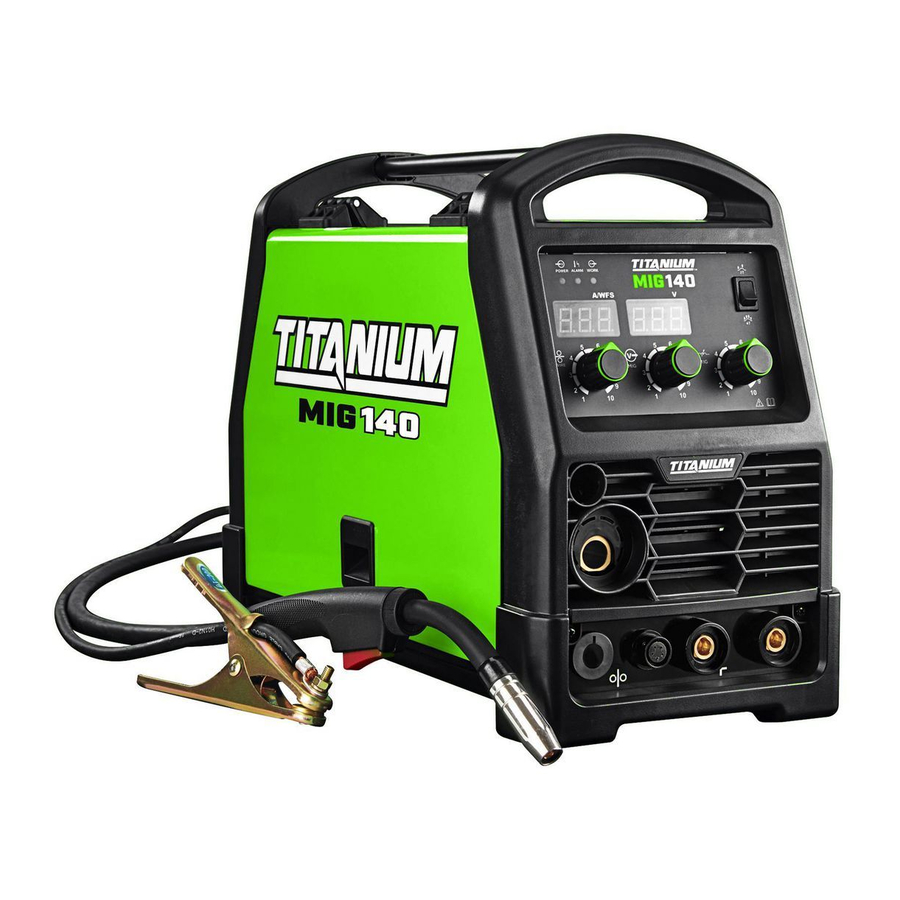
TITANIUM MIG 170, MIG 140, 57863, 57864 - Professional Welder Manual
- Owner's manual & safety instructions (33 pages) ,
- Owner's manual & safety instructions (32 pages)
Advertisement
Symbology
 | Wire Feed (Speed) |
 | Workpiece Ground Cable |
 | Torch Cable |
 | Overheat Shutdown Indicator |
 | Cooling Fan |
 | Housing Ground Point |
| VAC | Volts Alternating Current |
| A | Amperes |
| OCV | Open Circuit Voltage |
| KVA | Kilovolt Amperes (Volts / 1000 * Amperes) |
| IPM | Inches Per Minute |
| AWG | American Wire Gauge |
 | Electric Shock Hazard. Do not touch energized parts. |
 | Inhalation Hazard. Keep head out of fumes and use proper ventilation. |
 | Read manual before setup and/or use. |
 | Fire Hazard. Keep flammable materials away during welding. Spatter can cause accidental fires. |
 | Arc Ray Hazard. Wear welding helmet with properly rated filter lens. |
 | Pacemaker Hazard. Welding processes may interfere with pacemakers. Consult doctor before use. |
Specifications
| Model | Mig 140 | Mig 170 |
| Item | 57863 | 57864 |
| Power Input | 120 VAC / 60 Hz | 120/240 VAC / 60 Hz |
| Current Input | 23 A | 24 A @ 120V 26.8 A @ 240V |
| Welding Current Range | 30 –140 A | 120V: 30-140A 240V: 30-170A |
| Rated Duty Cycle | 30% @ 90 A | 40% @ 90 A, 120V input 25% @ 160A, 240V input |
| Open Circuit Voltage | 69 VDC | |
| Wire Speed | 80 – 275 IPM | 80 – 400 IPM |
| Welding Wire Capacity | Solid Core: 0.025" / 0.030" / 0.035" Flux Cored: 0.030" / 0.035" | |
| Wire Spool Capacity | Up to 12 lb spool | |
Setup
 Read the ENTIRE IMPORTANT SAFETY INFORMATION section at the beginning of this manual including all text under subheadings therein before set up or use of this product.

TO PREVENT SERIOUS INJURY FROM ACCIDENTAL OPERATION:
Turn the power Switch off and unplug the Welder before setup.
Note: Remove the protective foam and cardboard from the Welder before setup.
Wire Spool Installation / Wire Setup
Note: Wire Spool sold separately.
- Turn the power Switch OFF and unplug the Welder before proceeding.

- Pull up on the Door Latch, then open the Door.

- 2 Pound Wire Spool installation:
Remove the Wingnut, Keyed Washers, and Spring. If replacing a Spool, remove the old Spool and all remaining wire from the liners.

- Place the new Wire Spool over the Spool Spindle and against the Spool Brake Pad as illustrated.
To prevent wire feed problems, set the Spool so that it will unwind counterclockwise. - Line up the Keyed Washers with the groove on the Spindle. Replace the Keyed Washers and Spring over the Spool Spindle and secure Spool in place with the Wingnut.


Notice: If Wire Spool can spin freely, Wingnut is too loose. This will cause the welding wire to unravel and unspool which can cause tangling and feeding problems
- 10-12 pound Wire Spool installation:
Remove the Wingnut, Keyed Washers, and Spring. If replacing a Spool, remove the old Spool and all remaining wire from the liners.

- Place the Spool Adapter over the Spool Spindle and against the Spool Brake Pad as illustrated.

- Place the new Wire Spool over the Adapter and line up pin on Adapter with hole in Spool.
To prevent wire feed problems, set the Spool so that it will unwind counterclockwise. - Line up the Keyed Washers with the groove on the Spindle. Replace the Keyed Washers must and Spring over the Spool Spindle and unwind secure Spool in place with the Wingnut.


Notice: If Wire Spool can spin freely, Wingnut is too loose. This will cause the welding wire to unravel and unspool which can cause tangling and feeding problems.
- Screw the Spool Knob into the Spool Adapter.
- DCEN Direct Current Electrode Negative Wire Setup for Flux-Cored (gasless) welding:
Connect the Wire Feed Connector to the Negative Terminal on the front of the Welder.
Connect the Ground Cable to the Positive Terminal on the front of the Welder.

- DCEP Direct Current Electrode Positive Wire Setup for Solid Core (gas shielded) welding:

- Connect the Wire Feed Connector to the Positive Terminal on the front of the Welder.
Connect the Ground Cable to the Negative Terminal on the front of the Welder. - Determine which type of shielding gas would be appropriate for the welding you will do. Refer to the Settings Chart on the inside of the Welder door.
- With assistance, set the cylinder (not included) onto a cabinet or cart near the Welder and secure the cylinder in place with two straps (not included) to prevent tipping.

- Remove the cylinder's cap. Stand to the side of the valve opening, then open the valve briefly to blow dust and dirt from the valve opening. Close the cylinder valve.
- Locate the Regulator (included) and close its valve until it is loose, then thread Regulator onto cylinder and wrench tighten connection.
- Connect the Wire Feed Connector to the Positive Terminal on the front of the Welder.


Note: When using C100 shielding gas, connect a CGA 580/320 adapter (not included) to the inlet connection of the Regulator and wrench tighten. Thread the adapter onto the gas cylinder and wrench tighten.
- Attach the Gas Hose (included) to the Regulator's outlet and the Welder's gas inlet. Wrench-tighten both connections.
- Connect the Wire Feed Gas Hose within the Welder to the Gas Quick Connector. The collar on the Gas Quick Connector must click into place after attaching any hose to it.
- Turn the Feed Tensioner knob counterclockwise to loosen it enough to pull it down to remove tension. The spring-loaded Idler Arm will move up as shown.

- Feed Roller instructions:
Check that the Feed Roller is correct for the type of wire being used (solid core or fluxcored) and that it is turned to properly match the wire size marked on the Wire Spool:

- Unscrew the Feed Roller Knob counterclockwise.
- Remove the Feed Roller Knob to expose the Feed Roller.
- Flip or replace the Feed Roller as needed and confirm that it is the correct Roller for the type of wire being used and that the number showing is the same as the wire diameter on the Spool.
Note: The knurled groove is used for flux-cored wire. The V-grooves are used for solid / MIG wire. - Screw the Feed Roller Knob back into place to secure the Feed Roller.
- Loosen the Knob on the Wire Feed mechanism, then insert the Gun Cable Connector through the hole on the Welder front and into the socket on the Wire Feed.

- Ensure that the Gun Cable Connector is fully inserted into the socket on the Wire Feed mechanism as shown.
No O-ring should be visible.
Tighten the Knob securely.
If Connector is not fully inserted, the gas connection will leak, preventing shielding gas from reaching the welding arc.


NOTICE: To prevent damage, do not overtighten the Knob.
- Connect the Wire Feed Control Cable to the Wire Feed Control Socket located on the front of the machine. Press it in until the collar snaps into place. Note that the plug on the Cable fits into the Socket in one specific orientation only. To disconnect it, pull the collar back first.


Securely hold onto the end of the welding wire and keep tension on it during the following steps.
If this is not done, the welding wire will unravel and unspool which can cause tangling and feeding problems.
- Cut off all bent and crimped wire. The cut end must have no burrs or sharp edges; cut again if needed.
- Keep tension on the wire and guide at least 12 inches of wire into the Wire Inlet Liner and Feed Guide.

- Make sure the welding wire is resting in the groove of the Feed Roller, then push the wire Idler Arm down, and swing the Feed Tensioner up to latch it across the tip of the arm.
After the wire is held by the Tensioner, you may release it.

Note: The tension should be 3 – 5 for solid wire and 2 – 3 for flux-cored wire. Too much force on flux-cored wire will crush it and may cause feeding issues. - Pull and twist the Nozzle to remove it.
- Unscrew the Contact Tip counterclockwise and remove.
- Lay the MIG Gun Cable out in a straight line so that the welding wire moves through it easily. Leave the cover open, so that the feed mechanism can be observed.


Stainless steel wire is less flexible than other welding wire. therefore, it is more difficult to feed through the liner and gun.
It is especially important to keep the gun cable straight while feeding stainless steel wire.

The following steps require applying power to the Welder with the cover open.
To prevent serious injury from fire or electric shock:
- Do not touch anything, especially not the ground clamp, with the gun or welding wire or an arc will be ignited.
- Do not touch internal Welder components while it is plugged in.
- Turn the Power Switch off and do not touch the Gun's Trigger and before connecting Power Cord:
- 57863 only: Plug the Power Cord into a properly grounded, GFCI protected 120 VAC (20 amp rated) receptacle that matches the plug and turn the Power Switch ON.
- 57864 only:
![]()
Change the Voltage Switch on the back of the Welder to the voltage of the outlet you will use.
If using 120VAC, connect the included adapter to the end of the Power Cord. If using 240VAC, do not use the adapter. Plug the Power Cord into a properly grounded and rated receptacle that matches the plug and selected voltage and turn the Power Switch ON.

Voltage switch and plug need to be changed at the same time.
Note: The circuit must be equipped with delayed action-type circuit breaker or fuses.
- Set the MIG Flux / Spool Gun Switch to MIG Flux Gun.

- Point the Gun away from all objects. Press and hold the Trigger until the wire feeds through the end of the Gun two inches.
The wire liner may come out with the welding wire. This is normal, just turn off the Welder and push the wire liner back into the gun.
If the wire does not feed properly and the Spool is stationary, turn OFF and unplug the Welder and slightly tighten the Feed Tensioner clockwise before retrying. - To check the wire's drive tension, press and hold Trigger to feed the wire against a piece of wood from 2 to 3 inches away.
If the wire stops instead of bending, unplug the Welder, slightly tighten the Feed Tensioner clockwise, and try again. If the wire bends from the feed pressure, then the tension is set properly.

- Turn OFF the Power Switch and unplug the Power Cord from its electrical outlet.
- Select a Contact Tip that is compatible with the welding wire used. Slide the Contact Tip over the wire and thread it clockwise into the MIG Gun. Tighten the Contact Tip.

- Replace the Nozzle and cut the wire off at 1/2" from tip (1/2" stickout).
- Close the Door. Make sure Door is securely latched.


Basic Welding
Read the ENTIRE IMPORTANT SAFETY INFORMATION section at the beginning of this manual including all text under subheadings therein before welding.
TO PREVENT SERIOUS INJURY:
Protective gear must be worn when using the Welder; minimum shade number 10 full face shield (or welding mask), ear protection, welding gloves, sleeves and apron, NIOSH-approved respirator, and fire resistant work clothes without pockets should be worn when welding.
Light from the arc can cause permanent damage to the eyes and skin.
Do not breathe arc fumes.

Flux-cored wire welding is used to weld mild steel and stainless steel without shielding gas.
MIG welding uses solid wire and shielding gas, and is used to weld mild steel and stainless steel. MIG welding can also be used to weld thinner workpieces than flux-cored welding can.
Aluminum welding can be performed with an optional Spool Gun (sold separately) using aluminum wire and shielding gas.
Good welding takes a degree of skill and experience. Practice a few sample welds on scrap before welding your first project. Additional practice periods are recommended whenever you weld:
- a different thickness of material
- a different type of material
- a different type of connection
- using a different process (MIG vs. Flux)
Make practice welds on pieces of scrap to practice technique before welding anything of value.

TO PREVENT SERIOUS INJURY, FIRE AND BURNS:
Keep welding tip clear of grounded objects whenever unit is plugged in and turned on.

Practice your welding technique on scrap pieces before welding anything of value.
Front panel controls

Alarm Indicator: Lights up if there is a problem with welder operation.
See Alarm Indicator Error CodeS.
Wire Speed Knob: Controls the speed that the welding wire feeds out of the MIG Gun or Spool Gun and the output amperage of the Welder.
MIG Gun / Spool Gun Cable Socket: The MIG Gun and Spool Gun Cables connect here. The wire, welding current, and shielding gas (if performing MIG) feed to the welding gun through here.
Wire Feed Control Socket: Connect the Wire Feed Control Cable here.
Voltage Knob: This controls the output voltage.
Inductance Knob: This controls the output inductance.
2T/4T Switch: Use this to set the Gun Trigger operation to either 2T or 4T mode:
2T (2 touch) mode:
- Squeeze the trigger to start the welding current.
- Release trigger to stop the welding current.
4T (4 touch) mode:
- Squeeze trigger to start welding.
- Release trigger during welding.
- Squeeze and release trigger to shut welding current off.
Interior Controls

Note: When using an optional Spool Gun (sold separately), disconnect the Wire Feed Gas Hose from the Gas Quick Connector, thread the gas hose from the Spool Gun through the round hole in the front of the Welder and connect it to the Gas Quick Connector, and place the MIG Flux/Spool Gun Switch on the Spool Gun setting. For all other welding, place the MIG Flux/Spool Gun Switch on the MIG Flux Gun setting and connect the Wire Feed Gas Hose to the Gas Quick Connector. The collar on the Gas Quick Connector must click into place after attaching any hose to it.
Weld Settings
Refer to the Settings Chart on the inside of the Welder door for Flux-Cored and MIG Weld settings. The chart is only intended to show general guidelines for different wire sizes and for different thicknesses of material. The initial settings used at the beginning of a weld may need to be adjusted after stopping and carefully inspecting the weld. Proper welding takes experience.
Duty Cycle (Duration of Use)
Avoid damage to the Welder by not welding for more than the prescribed duty cycle time.
The Duty Cycle defines the number of minutes, within a 10 minute period, during which a given welder can produce a particular welding current without overheating.
For example, a welder with a 40% duty cycle at 90 A welding current must be allowed to rest for at least 6 minutes after every 4 minutes of continuous welding.
Failure to carefully observe any duty cycle limitations can easily over-stress a welder's power generation system contributing to premature welder failure.

This Welder has an internal thermal protection system to help prevent this sort of over-stress. When the Welder overheats, it automatically shuts down and the Overload Indicator lights. The Welder automatically returns to service after cooling off. Should this occur, rest the MIG Gun on an electrically non-conductive, heat-proof surface, such as a concrete slab, well clear of the ground clamp.
Allow the Welder to cool with the power Switch on, so that the internal Fan will help cool the Welder.
When the Overload Indicator is no longer lit and the Welder can be used again, use shorter welding periods and longer rest periods to prevent needless wear.

Setting up the Weld
- Make practice welds on pieces of scrap the same thickness as your intended workpiece to practice technique before welding anything of value. Clean the weld surfaces thoroughly with a wire brush or angle grinder; there must be no rust, paint, oil, or other materials on the weld surfaces, only bare metal.
- Use clamps (not included) to hold the workpieces in position so that you can concentrate on proper welding technique. The distance (if any) between the two workpieces must be controlled properly to allow the weld to hold both sides securely while allowing the weld to penetrate fully into the joint. The edges of thicker workpieces may need to be chamfered (or beveled) to allow proper weld penetration.


Notice: When welding equipment on a vehicle, disconnect the vehicle battery power from both the positive connection and the ground before welding.
This prevents damage to some vehicle electrical systems and electronics due to the high voltage and high frequency bursts common in welding.
- Clamp Ground Cable to bare metal on the workpiece near the weld area, or to metal work bench where the workpiece is clamped.

- Set the Wire Speed, Voltage, and Inductance Knobs to the desired settings. Refer to the Settings Chart on the inside of the Welder door.
![]()


Note: The initial settings may need to be adjusted after stopping and carefully inspecting the weld. Proper welding takes experience.

TO PREVENT DEATH FROM ASPHYXIATION:
Do not open gas without proper ventilation.
Fix gas leaks immediately.
Shielding gas can displace air and cause rapid loss of consciousness and death.
Shielding gas without carbon dioxide can be even more hazardous because asphyxiation can start without feeling shortness of breath.
- Gas shielded, solid-core wire only:
- Open gas cylinder valve all the way.
- Set Flow Gauge to SCFH value indicated on Settings Chart.
- Turn the Power Switch off and do not touch the Gun's Trigger and before connecting Power Cord:
- 57863 only: Plug the Power Cord into a properly grounded, GFCI protected 120 VAC (20 amp rated) receptacle that matches the plug and turn the Power Switch ON.
- 57864 only:
![]()
Change the Voltage Switch on the back of the Welder to the voltage of the outlet you will use.
If using 120VAC, connect the included adapter to the end of the Power Cord. If using 240VAC, do not use the adapter. Plug the Power Cord into a properly grounded and rated receptacle that matches the plug and selected voltage and turn the Power Switch ON.

Voltage switch and plug need to be changed at the same time.
Note: The circuit must be equipped with delayed action-type circuit breaker or fuses.
- Set MIG Gun down on nonconductive, nonflammable surface away from any grounded objects. Turn the Power Switch ON.
![]()

Basic Welding technique
- Press (and hold) Trigger and contact the area to be welded with electrode wire to ignite arc.
- For a narrow weld, you can usually draw the wire in a steady straight line.
This is called a stringer bead.
![]()
For a wider weld, draw the wire back and forth across the joint.
This is called a weave bead and takes practice to perform properly.
![]()
- Direct the welding wire straight into the joint. This gives an angle of 90° (straight up and down) for butt (end to end) welds, and an angle of 45° for fillet (T-shaped) welds.

Weld Mig gun angles, viewed from front of weld joint.
- For MIG welding using solid wire and shielding gas, the end of the MIG Gun should be tilted so that wire is angled anywhere in-between straight on and 15° away from the direction you are welding. The amount of tilt is called the push angle.

- When using flux-cored wire without shielding gas, the end of the MIG Gun should be tilted so that wire is angled anywhere in-between straight on and 15° in the direction you are welding.
The amount of tilt is called the drag angle. - The Contact Tip should remain within 1/2' of the work surface. This distance is called CTWD - Contact Tip to Work Distance.
![]()


Note: If Welder is used too long, the Overload Indicator lights up and the unit automatically shuts down. The Welder automatically returns to service after cooling off. Should this occur, rest the MIG Gun on an electrically nonconductive, heat-proof surface, such as a concrete slab, away from the ground clamp.
Allow the Welder to cool with the power Switch on, so that the internal Fan will help cool the Welder.
When the Overload Indicator is no longer lit and the Welder can be used again, use shorter welding periods and longer rest periods to help prevent needless wear.

- After welding the test weld on a piece of scrap for a few seconds, stop, and check your progress. Clean, then compare your weld's appearance with the diagrams and descriptions in the Welding tips section. After making any necessary adjustments, continue to weld while carefully following the DUTY CYCLE guidelines.
![]()
Weld will be hot, do not touch. - When welding is complete, set the MIG Gun down on a heat-proof, electrically non-conductive surface.
Turn the Power Switch OFF.

- Allow Welder to cool down, then unplug the Power Cord.
![]()
- Remove Ground Clamp from workpiece or table and disconnect MIG Gun.
- Respool wire by clipping wire, removing gas nozzle/contact tip on MIG Gun, releasing Idler Arm on Wire Feed mechanism, and rotating the Wire Spool counterclockwise. Be sure to securely hold wire as it is being respooled because the end of wire has a tendency to quickly unravel once it clears the wire feeder.
- MIG ONLY:
Close shielding gas cylinder valve securely. Remove Regulator and replace cap. Disconnect Gas Hose from Welder. Store and secure gas cylinder.
![]()


Welding Tips
A good way to test welding technique is to examine a weld's appearance after it has cooled and the slag has been removed. Then, better welding can be learned by adjusting your weld technique to remedy any problems found.

Cleaning the Weld
TO PREVENT SERIOUS INJURY:
Continue to wear ANSI-approved safety goggles and protective wear when cleaning a weld.
Sparks or chips may fly when cleaning.

- A weld from flux-cored wire will be covered by slag. Use a chipping hammer to knock this off. Be careful not to damage the weld or base material.

- Use a wire brush to further clean the weld or use an angle grinder (sold separately) to shape the weld.

Strike Test
A test weld on a PIECE OF SCRAP can be tested by using the following procedure.
WEAR ANSI-APPROVED SAFETY GOGGLES DURING THIS PROCEDURE.
TO PREVENT SERIOUS INJURY:
This test Will damage the weld it is performed on.
This test is ONLY an indicator of weld technique and is not intended to test working welds.
- After two scraps have been welded together and the weld has cooled, clamp one scrap in a sturdy vise.
- Stay clear from underneath while you strike the opposite scrap with a heavy hammer, preferably a dead-blow hammer.
- A GOOD WELD will deform but not break, as shown on top.
A POOR WELD will be brittle and snap at the weld, as shown on bottom.


Weld Diagnosis
Workpiece Heat Control / Weld Penetration

How to increase workpiece heat and increase penetration: (to weld THICKER workpieces properly)
- Increase weld current
- Decrease travel speed
- Use faster wire feed
- Use shorter CTWD
How to reduce workpiece heat and limit penetration: (to weld THINNER workpieces properly)
- Decrease weld current
- Increase travel speed
- Use slower wire feed
- Use longer CTWD
Example Weld Diagrams

Weld Problems
Penetration (Workpiece Heat Control)

EXCESS PENETRATION OR BURN-THROUGH
POSSIBLE CAUSES AND SOLUTIONS
- Workpiece overheating:
Reduce wire feed speed.
Decrease weld current. - Travel speed too slow:
Increase travel speed and ensure that travel speed is kept steady. - Excessive material at weld:
Reduce wire feed speed.
INADEQUATE PENETRATION
POSSIBLE CAUSES AND SOLUTIONS
- Incorrect welding technique:
Maintain 1/2" or less CTWD.
Keep arc on leading edge of weld puddle.
Hold MIG Gun at proper angles. - Insufficient weld heat:
Reduce travel speed.
Increase weld current. - Workpieces too thick/close:
Bevel thick workpieces, allow slight gap, and weld in several passes. - Insufficient weld material:
Increase wire feed speed.
Bend at Joint

POSSIBLE CAUSES AND SOLUTIONS
- Improper clamping:
Clamp workpieces securely.
Make tack welds to hold workpieces. - Excessive heat:
Weld a small portion and allow to cool before proceeding.
Increase travel speed.
Reduce wire feed speed.
Coat of Slag Over Weld
Slag is a necessary part of a flux-cored wire weld. it shields the weld from impurities.
Clean off the slag with a chipping Hammer and Wire Brush after welding.
Gas-shielded Mig welds are protected by the shielding gas and do not need slag to protect them.

Weld Not Adhering Properly
Gaps present between weld and previous bead or between weld and workpiece. See areas below.

POSSIBLE CAUSES AND SOLUTIONS
- Incorrect welding technique:
Place stringer bead at correct place in joint.
Adjust workpiece position or weld angle to permit proper welding to bottom of piece.
Pause briefly at sides during weave bead.
Keep arc on leading edge of weld puddle.
Hold MIG Gun at proper angles. - Insufficient weld heat:
Increase current. Increase wire feed speed. - Dirty workpiece:
Clean workpiece down to bare metal. - Insufficient weld material:
Increase wire feed speed. - Workpiece gap too narrow:
Widen groove or increase bevel.
Porosity

Small cavities or holes in the bead.
POSSIBLE CAUSES AND SOLUTIONS
- Incorrect polarity: Check that polarity is set correctly for type of welding.
- Insufficient shielding gas (MIG only): Increase flow of gas. Clean nozzle. Maintain proper CTWD.
- Incorrect shielding gas (MIG only): Use shielding gas recommended by wire supplier.
- Dirty workpiece or welding wire: Clean workpiece down to bare metal. Make certain that wire is clean and free from oil, coatings, and other residues.
- Inconsistent travel speed: Maintain steady travel speed.
- CTWD too long: Reduce CTWD.
Excessive Spatter

Fine spatter is normal. Spatter that is grainy and large is a problem.
POSSIBLE CAUSES AND SOLUTIONS
- Dirty workpiece or welding wire:
Clean workpiece down to bare metal.
Make certain that wire is clean and free from oil, coatings, and other residues. - Incorrect polarity:
Check that polarity is set correctly for type of welding. - Insufficient shielding gas (MIG only):
Increase flow of gas.
Clean nozzle.
Maintain proper CTWD. - Wire feeding too fast:
Reduce wire feed speed. - CTWD too long:
Reduce CTWD.
Crooked/Wavy Bead

POSSIBLE CAUSES AND SOLUTIONS
- Inaccurate welding:
Use two hands or rest hand on steady surface. - Inconsistent travel speed:
Maintain steady travel speed. - CTWD too long:
Reduce CTWD.
Burn-Through

Base material melts away, leaving a hole in the weld.
POSSIBLE CAUSES AND SOLUTIONS
- Workpiece overheating:
Reduce current and/or wire feed speed. - Travel speed too slow:
Increase travel speed and ensure that travel speed is kept steady. - Excessive material at weld:
Reduce wire feed speed.
Maintenance
TO PREVENT SERIOUS NIJURY, FIRE AND BURNS:
Unplug the Welder, rest the Mig gun on a heat-proof, electrically non-conductive surface, and allow all parts of the Welder to cool thoroughly before service.
- BEFORE EACH USE, inspect the general condition of the Welder. Check for:
- loose hardware
- misalignment or binding of moving parts
- damaged cord / e lectrical wiring
- frayed or damaged cables
- cracked or broken parts
- any other condition that may affect its safe operation.
- Periodically, have a qualified technician remove the Rear Panel and use compressed air to blow out all dust from the interior.
- Store in a clean and dry location.
- For optimal weld quality, clean and inspect the Contact Tip and Nozzle before each use, as explained below.
Nozzle and Contact Tip Inspection and Cleaning
- Make sure that the entire MIG Gun is completely cool and that the Power Cord is unplugged from the electrical outlet before proceeding.
- Pull the Nozzle to remove it.
- Scrub the interior of the Nozzle clean with a wire brush.
- Examine the end of the Nozzle. The end should be flat and even. If the end is uneven, chipped, melted, cracked, or otherwise damaged, the Nozzle will adversely effect the weld and should be replaced.
- Unscrew the Contact Tip counterclockwise and slide it off the welding wire to remove.
- Scrub the outside of the Tip clean with a wire brush. Clean out the inside of the tip with a tip cleaner (sold separately). Check that the Tip is the proper type for the wire size used.
- Examine the shape of the hole at the end of the Contact Tip. It should be an even circle; it should not be oblong or have any bulges in it.
- If any problems are noted, replace the Contact Tip. Select a new Tip of the correct size for the welding wire used.
- Reinstall the Tip and securely reinstall the Nozzle as well.


Alarm Indicator Error Codes
| Code | Meaning | Solution |
 (Error Voltage) | (57864 only) Input voltage and Voltage Switch setting do not match. | (57864 only) Flip Voltage Switch. |
 (Over-current) | Welder is using too much current. Welder may pull too much current from supply. | Reduce current/wire speed using Wire Speed Knob. |
 (Error Short) | Electrode has shorted against workpiece, no arc is detected. The electrode is stuck against the workpiece, allowing all current to go directly through without welding. | Free the electrode from the plate. |
| Alarm indicator without code. Fan keeps running. | Welder has overheated. Duty Cycle was likely exceeded. | Follow instructions under Duty Cycle (Duration of Use). |
Troubleshooting
Be CERTAIN to shut off the Welder, disconnect it from power, and discharge the MIG Gun to ground before adjusting, cleaning, or repairing the unit.
| Problem | Possible Causes | Likely Solutions |
| Wire feed motor runs but wire does not feed properly |
|
|
Wire creates a bird's nest during operation |
|
|
Wire stops during welding |
|
|
Welding arc not stable |
|
|
Weak arc strength |
|
|
| When switched on, Power Indicator lights but Welder does not function |
|
|
Power ON Indicator does not light when switched on |
|
|
| Follow all safety precautions whenever diagnosing or servicing the equipment. | ||
For technical questions, please call 1-888-380-0318.
Visit our website at: http://www.harborfreight.com
Email our technical support at: productsupport@harborfreight.com
Copyright © 2020 by Harbor Freight Tools. All rights reserved. No portion of this manual or any artwork contained herein may be reproduced in any shape or form without the express written consent of Harbor Freight Tools.
Diagrams within this manual may not be drawn proportionally. Due to continuing improvements, actual product may differ slightly from the product described herein.
Tools required for assembly and service may not be included.

Documents / Resources
References
Download manual
Here you can download full pdf version of manual, it may contain additional safety instructions, warranty information, FCC rules, etc.
Download TITANIUM MIG 170, MIG 140, 57863, 57864 - Professional Welder Manual
Advertisement


Need help?
Do you have a question about the MIG 170 and is the answer not in the manual?
Questions and answers