Table of Contents
Advertisement
Owner's Manual & Safety Instructions
Save This Manual
operating, inspection, maintenance and cleaning procedures. Write the product's serial number in the
back of the manual near the assembly diagram (or month and year of purchase if product has no number).
Keep this manual and the receipt in a safe and dry place for future reference.
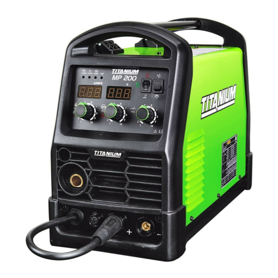
UNLIMITED 200
64806
Email our technical support at: productsupport@harborfreight.com
When unpacking, make sure that the product is intact
and undamaged. If any parts are missing or broken,
please call 1-888-380-0318 as soon as possible.
Copyright
©
2018 by Harbor Freight Tools
No portion of this manual or any artwork contained herein may be reproduced in
any shape or form without the express written consent of Harbor Freight Tools.
Diagrams within this manual may not be drawn proportionally. Due to continuing
improvements, actual product may differ slightly from the product described herein.
Tools required for assembly and service may not be included.
Keep this manual for the safety warnings and precautions, assembly,
Visit our website at: http://www.harborfreight.com
®
. All rights reserved.
™
Read this material before using this product.
Failure to do so can result in serious injury.
SAVE THIS MANUAL.
18g
Advertisement
Table of Contents

Related Manuals for Titanium UNLIMITED 200


Summary of Contents for Titanium UNLIMITED 200
- Page 1 Write the product’s serial number in the back of the manual near the assembly diagram (or month and year of purchase if product has no number). Keep this manual and the receipt in a safe and dry place for future reference. UNLIMITED 200 ™ 64806 Visit our website at: http://www.harborfreight.com...
-
Page 2: Table Of Contents
table of contents Safety ............2 Welding Tips ..........31 Specifications ..........7 Maintenance ..........35 Setup ............10 Parts List and Diagram ......38 Basic Welding ..........17 Warranty ............ 40 Warning SyMBolS and dEFinitionS This is the safety alert symbol. It is used to alert you to potential personal injury hazards. - Page 3 Fume and gas Safety INHALATION HAZARD: Welding and plasma cutting produce toxic fumes. 1. Exposure to welding or cutting exhaust 3. keep head out of fumes. fumes can increase the risk of developing Do not breathe exhaust fumes. certain cancers, such as cancer of the 4.
-
Page 4: Electrical Safety
Electrical Safety ElEctric SHock can kill. 1. turn off, disconnect power, and 6. do not expose welders to rain or wet conditions. discharge electrode to ground before setting Water entering a welder will increase down torch/electrode holder and before service. the risk of electric shock. - Page 5 Welder Use and care 1. do not use the welder if the switch does not turn 4. Store idle welders out of the reach of it on and off. Any welder that cannot be controlled children and do not allow persons unfamiliar with the switch is dangerous and must be repaired.
-
Page 6: Extension Cords
grounding to prEVEnt ElEctric SHock and dEatH FroM incorrEct groUnding WirE connEction: check with a qualified electrician if you are in doubt as to whether the outlet is properly grounded. do not use the Welder if the power cord or plug is damaged. if damaged, have it repaired by a service facility before use. -
Page 7: Specifications
Symbology Wire Feed (Speed) Inches Per Minute American Wire Gauge Workpiece Ground Cable Electric Shock Hazard. Torch Cable Do not touch energized parts. Overheat Shutdown Indicator Inhalation Hazard. Keep head out of fumes and use proper ventilation. Cooling Fan Read manual before Housing Ground Point setup and/or use. -
Page 8: Front Panel Controls
controls Front panel controls Work indicator Mode Switch alarm indicator 2T / 4T power Switch indicator Wire inductance Speed knob knob Voltage / Hot Start knob Mig gun / Spool gun positive cable Socket terminal Wire Feed control Socket negative Wire Feed terminal power cable... - Page 9 interior controls Mig Flux / S pool Gun Switch gas Quick Wire Spool connector Spool knob Feed idler tensioner Feed roller knob Wire inlet Wire Feed liner Mechanism note: When using an optional Spool Gun (sold separately), disconnect the Wire Feed Gas Hose from the Gas Quick Connector, thread the gas hose from the Spool Gun through the round hole in the front of the Welder and connect it to the Gas Quick Connector, and place the MIG Flux/Spool Gun Switch on the Spool Gun setting.
-
Page 10: Setup
Wire Welding read the EntirE iMportant SaFEty inForMation section at the beginning of this manual including all text under subheadings therein before set up or use of this product. to prEVEnt SErioUS inJUry FroM accidEntal opEration: turn the power Switch off and unplug the Welder before setup. note: Remove the protective foam and cardboard from the Welder before setup. - Page 11 6. 10-12 pound Wire Spool installation: Spool knob Remove the Wingnut, Keyed Washers, and Spring. Wingnut If replacing a Spool, remove the old Spool and all remaining wire from the liners. keyed Washer Spring keyed Washer 7. Place the Spool Adapter over the Spool Spindle and against the Spool Brake Pad as illustrated.
- Page 12 12. dcEp direct current Electrode positive Wire Setup for Solid Core (gas shielded) welding: a. Connect the Wire Feed Connector to the Positive Terminal on the front of the Welder. Connect the Ground Cable to the Negative Terminal on the front of the Welder. connect connect Wire Feed...
- Page 13 Feed tensioner idler arm 13. Turn the Feed Tensioner knob counterclockwise to loosen it enough to pull it down to remove tension. The spring-loaded Idler Arm will move up as shown. Feed roller 14. Feed roller instructions: knob Check that the Feed Roller is correct for the type of wire being used (solid core or flux- cored) and that it is turned to properly match the wire size marked on the Wire Spool:...
- Page 14 Wire Feed gun cable knob 15. Loosen the Knob on the Wire Feed Mechanism connector mechanism, then insert the Gun Cable Connector through the hole on the Welder front and into the socket on the Wire Feed. 16. Ensure that the Gun Cable Connector is fully inserted into the socket on the Wire Feed mechanism as shown.
- Page 15 20. Make sure the welding wire is resting in the groove idler arm Feed tensioner of the Feed Roller, then push the wire Idler Arm down, and swing the Feed Tensioner up to latch it across the tip of the arm. After the wire is held by the Tensioner, you may release it.
- Page 16 29. Set the MIG Flux / S pool Gun Switch MIG Flux / Spool gun Switch to MIG Flux Gun. Mig gun 30. Point the Gun away from all objects. Press and hold the Trigger until the wire feeds through the end of the Gun two inches.
-
Page 17: Basic Welding
Basic Welding read the EntirE iMportant SaFEty inForMation section at the beginning of this manual including all text under subheadings therein before welding. to prEVEnt SErioUS inJUry: protective gear must be worn when using the Welder; minimum shade number 10 full face shield (or welding mask), ear protection, welding gloves, sleeves and apron, NIOSH-approved respirator, and fire resistant work clothes without pockets should be worn when welding. - Page 18 Duty Cycle (Duration of Use) avoid damage to the Welder by not welding Failure to carefully observe any duty cycle limitations for more than the prescribed duty cycle time. can easily over-stress a welder’s power generation The Duty Cycle defines the number of minutes, within a system contributing to premature welder failure.
- Page 19 Setting Up the Weld 1. Make practice welds on pieces of scrap the same thickness as your intended workpiece to practice technique before welding anything of value. Clean the weld surfaces thoroughly with a wire brush or angle grinder; there must be no rust, paint, oil, or other materials clamps on the weld surfaces, only bare metal.
- Page 20 dangEr! to prEVEnt dEatH FroM aSpHyXiation: do not open gas without proper ventilation. Fix gas leaks immediately. Shielding gas can displace air and cause rapid loss of consciousness and death. Shielding gas without carbon dioxide can be even more hazardous because asphyxiation can start without feeling shortness of breath.
-
Page 21: Basic Welding Technique
Basic Welding technique 1. Press (and hold) Trigger and contact the area to be welded with electrode wire to ignite arc. stringer bead weave bead 2. For a narrow weld, you can usually draw the wire in a steady straight line. This is called a stringer bead. - Page 22 note: If Welder is used too long, the Overload Indicator lights up and the unit automatically shuts down. The Welder automatically returns to service after cooling off. Should this occur, rest the MIG Gun on an electrically non- Mig gun overload conductive, heat-proof surface, such as a indicator...
-
Page 23: Important Safety Information
TIG / S tick Welding read the EntirE iMportant SaFEty inForMation section at the beginning of this manual including all text under subheadings therein before set up or use of this product. to prEVEnt SErioUS inJUry FroM accidEntal opEration: turn the power Switch off and unplug the Welder before setup. -
Page 24: Connect Shielding Gas
connect Shielding gas 1. Determine which type of shielding gas would be appropriate for the welding you will do. Refer to the Settings Chart on the inside of the Welder door. 2. With assistance, set the cylinder (not included) onto a cabinet or cart near the Welder and secure the cylinder in place with two straps (not included) to prevent tipping. - Page 25 Sharpen tungsten Electrode To avoid Electrode contamination, dedicate a fine grit grinding wheel exclusively to Electrode grinding. Warning! Some Electrodes may contain 5. Lightly press Electrode tip materials that are hazardous to breathe. against the surface of Electrode Wear a respirator and ANSI-approved safety the grinding wheel at an angle.
- Page 26 Stick Setup connect cables Electrode Holder cable in positive Socket Electrode Holder ground clamp cable in negative Socket ground clamp 1. Plug Ground Clamp Cable into Negative Socket. 2. Plug Electrode Holder Cable into Positive Socket. Twist clockwise all the way to lock in place. Twist clockwise all the way to lock in place.
- Page 27 Basic TIG / S tick Welding read the EntirE iMportant SaFEty inForMation section at the beginning of this manual including all text under subheadings therein before set up or use of this product. to prEVEnt SErioUS inJUry: protective gear must be worn when using the Welder; minimum shade number 10 full face shield (or welding mask), ear protection, welding gloves, sleeves and apron, NIOSH-approved respirator, and fire resistant work clothes without pockets should be worn when welding.
- Page 28 Duty Cycle (Duration of Use) avoid damage to the Welder by not welding for more This Welder has an internal thermal protection system to than the prescribed duty cycle time. The Duty Cycle help prevent this sort of over-stress. When the Welder defines the number of minutes, within a 10 minute overheats, it automatically shuts down.
-
Page 29: Tig Welding
tig Welding to prEVEnt SErioUS inJUry and dEatH: do not weld without grounding clamp. When the operator is not holding the torch, it must be sitting on a nonconductive, nonflammable surface. only hold tig rod with an electrically insulated welding glove. to prEVEnt dEatH FroM aSpHyXiation: do not open gas without proper ventilation. -
Page 30: Stick Welding
Stick Welding to prEVEnt SErioUS inJUry and dEatH: do not weld without grounding clamp. When the operator is not holding the Electrode Holder, it must be sitting on a nonconductive, nonflammable surface. 1. Turn the Power Switch to the OFF position. After practice welding on scrap, stop, and 2. -
Page 31: Welding Tips
Welding tips A typical flux-cored wire (FCAW) weld before cleaning. weld bead slag spatter A good way to test welding technique is to examine a weld’s appearance after it has cooled and the slag base metal has been removed. Then, better welding can be learned by adjusting your weld technique to remedy A typical solid wire (GMAW) weld any problems found. - Page 32 Weld diagnosis Workpiece Heat control / Weld penetration EXcESS pEnEtration or inadEQUatE pEnEtration propEr pEnEtration BUrn-tHroUgH not hot enough ideal heat too hot How to increase workpiece heat How to reduce workpiece heat and increase penetration: and limit penetration: (to weld tHickEr workpieces properly) (to weld tHinnEr workpieces properly) a.
- Page 33 Weld problems Penetration (Workpiece Heat Control) EXcESS pEnEtration or propEr pEnEtration inadEQUatE pEnEtration BUrn-tHroUgH Weld is visible underneath and Weld does not penetrate the Weld droops on top and bulges slightly on top. joint fully, just on the surface. underneath, or falls through entirely, making a hole.
- Page 34 porosity Excessive Spatter Small cavities or holes in the bead. Fine spatter is normal. Spatter that is grainy and large is a problem. VIEW VIEW poSSiBlE caUSES and SolUtionS poSSiBlE caUSES and SolUtionS 1. incorrect polarity: Check that polarity is set correctly 1.
-
Page 35: Maintenance
Maintenance to prEVEnt SErioUS inJUry, FirE and BUrnS: Unplug the Welder, rest the Mig gun on a heat-proof, electrically non-conductive surface, and allow all parts of the Welder to cool thoroughly before service. 1. BEForE EacH USE, inspect the general 2. -
Page 36: Troubleshooting
alarm indicator Error codes code Meaning Solution Err Uol Input voltage and Voltage Switch Flip Voltage Switch. setting do not match. (Error Voltage) Our Cur Welder is using too much current. Reduce current/wire speed Welder may pull too much current from supply. using Wire Speed Knob. - Page 37 Troubleshooting (continued) iMportant! Be cErtain to shut off the Welder, disconnect it from power, and discharge the Mig gun to ground before adjusting, cleaning, or repairing the unit. problem possible causes likely Solutions 1. Wire not feeding properly. 1. See first Troubleshooting section above. 2.
-
Page 38: Parts List And Diagram
Troubleshooting (continued) iMportant! Be cErtain to shut off the Welder, disconnect it from power, and discharge the Mig gun to ground before adjusting, cleaning, or repairing the unit. problem possible causes likely Solutions 1. Improper ground connection. 1. Make certain that the workpiece is contacted properly by the Ground Clamp and that the workpiece is properly cleaned near the ground clamp and the welding location. -
Page 39: Assembly Diagram
assembly diagram record Serial number Here: note: If product has no serial number, record month and year of purchase instead. note: Some parts are listed and shown for illustration purposes only, and are not available individually as replacement parts. Parts may not be interchangeable. Specify number when ordering. Item 64806 For technical questions, please call 1-888-380-0318. -
Page 40: Warranty
plEaSE rEad tHE FolloWing carEFUlly THE MANUFACTURER AND/OR DISTRIBUTOR HAS PROVIDED THE PARTS LIST AND ASSEMBLY DIAGRAM IN THIS MANUAL AS A REFERENCE TOOL ONLY. NEITHER THE MANUFACTURER OR DISTRIBUTOR MAKES ANY REPRESENTATION OR WARRANTY OF ANY KIND TO THE BUYER THAT HE OR SHE IS QUALIFIED TO MAKE ANY REPAIRS TO THE PRODUCT, OR THAT HE OR SHE IS QUALIFIED TO REPLACE ANY PARTS OF THE PRODUCT.
Need help?
Do you have a question about the UNLIMITED 200 and is the answer not in the manual?
Questions and answers
How much wattage does it take to run this welder?
The wattage requirement for the Titanium UNLIMITED 200 welder can be estimated using the given current input values:
- At 120V:
- GMAW/FCAW: 22A → 120V × 22A = 2,640W
- SMAW: 24.9A → 120V × 24.9A = 2,988W
- GTAW: 20.8A → 120V × 20.8A = 2,496W
- At 240V:
- GMAW/FCAW: 36A → 240V × 36A = 8,640W
- SMAW: 33.6A → 240V × 33.6A = 8,064W
- GTAW: 28.7A → 240V × 28.7A = 6,888W
Thus, the maximum wattage requirement is approximately 8,640W at 240V.
This answer is automatically generated