Honeywell Home TH6220WF2006 Professional Install Manual
Hide thumbs
Also See for TH6220WF2006:
- Professional install manual (68 pages) ,
- Professional install manual (39 pages) ,
- User manual (108 pages)
Table of Contents
Advertisement
T6 Pro Smart
Programmable Thermostat
TH6220WF2006
TH6320WF2003
Professional Install
Guide
Package Includes:
• T6 Pro Smart Thermostat
• UWP™ Mounting System
• Decorative Cover Plate
• Screws and anchors
• Thermostat literature
Search for local rebates: HoneywellHome.com/Rebates
Read before installing
Compatibility
• Compatible with most heating, cooling, and heat pump systems
• Required: 24 VAC power ("C" wire)
• Input: 24 V ~ @ 60 Hz, 1 A
• Does not work with electric baseboard heat (120V-240V)
• Does not work with millivolt systems
• Android or iOS smartphone or tablet
Customer assistance
WEB customer.resideo.com
PHONE 1-800-633-3991
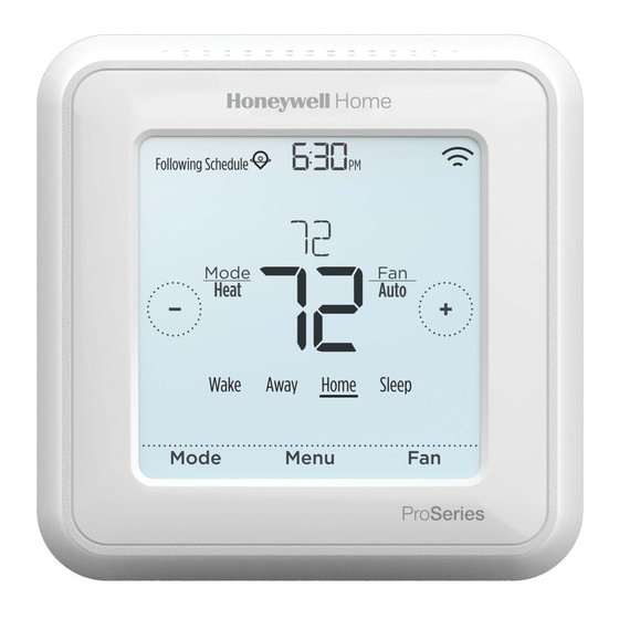
Following Schedule
PM
Mode
Fan
Heat
Auto
Wake Away Home Sleep
Mode
Menu
Fan
33-00392-09
Advertisement
Table of Contents

Related Manuals for Honeywell Home TH6220WF2006


Summary of Contents for Honeywell Home TH6220WF2006
- Page 1 T6 Pro Smart Programmable Thermostat Following Schedule TH6220WF2006 TH6320WF2003 Mode Heat Auto Professional Install Wake Away Home Sleep Guide Mode Menu Package Includes: • T6 Pro Smart Thermostat • UWP™ Mounting System • Decorative Cover Plate • Screws and anchors •...
- Page 2 UWP Mounting System installation 1. Open package to find the UWP. See Figure 1. 2. Position the UWP on the wall. Level and mark hole positions. See Figure 2. Drill holes at marked positions, and then lightly tap supplied wall anchors into wall using a hammer.
-
Page 3: Terminal Designations
Wiring UWP Push down on the tabs to put the wires into the inner holes of their corresponding termi nals on the UWP (one wire per terminal) until they are firmly in place. Gently tug on the wires to verify they are secure. If you need to release the wires again, push down the terminal tabs on the sides of the UWP. - Page 4 Setting Slider Tabs Set R Slider Tab, see Figure 9. • Use built-in jumper (R Slider Tab) to differentiate between one or two transformer systems. • If there is only one R wire, and it is connected to the R, Rc, or RH terminal on the old thermostat, set the slider to the up position (1 wire).
-
Page 5: Conventional Systems
Wiring NOTES: 1 Available wiring configurations differ by product models/product numbers. 2 Use 18- to 22- gauge thermostat wire. Shielded cable is not required. 3 Set the R Slider Tab on the UWP to the up position (1 wire) for 1 transformer systems or the down position (2 wires) for 2 transformer systems. - Page 6 Heat pumps systems 1H/1C Heat Pump System 2H/2C Heat Pump System Power Power [R+Rc joined by Slider Tab] [R+Rc joined by Slider Tab] Compressor contactor Compressor contactor (stage 1) 24VAC common 24VAC common O/B Changeover valve O/B Changeover valve Fan relay Fan relay Compressor contactor (stage 2) Heat pump fault input...
-
Page 7: Ventilation Systems
Ventilation systems NOTE: Ventilation is not available on all models. Using U Slider Tab Wired to ERV/HRV whole Wired to fresh air damper house ventilator with internal powered by furnace power supply. transformer. Mounting thermostat Push excess wire back into the wall opening. - Page 8 Installer setup – using the thermostat Setup using the thermostat • After the thermostat has powered up, touch START SETUP on the thermostat. You’ll be asked if you want to perform setup via app. Touch No. Back • Touch to toggle between Installer Set Up (ISU) options.
-
Page 9: Advanced Menu Options
Enter Contractor Mode To enter Contractor Mode, press and hold the Honeywell Home logo for 5 seconds. Then tap Confirm to begin using Contractor Mode. Follow steps to personally invite your customer to connect their Honeywell Home App. -
Page 10: Key Features
Key features System status Connection status Time, ISU #, or information information Alert # Cool On, Heat On Status of Wi-Fi Emergency Heat On, Connection: Connected, Recovery, or Auto Disconnected, or Wi-Fi Changeover On. is Off. Schedule information Messaging Heat On Recovery Following Schedule Auto Chg. - Page 11 Installer setup options (ISU) – advanced menu Table 1.
- Page 12 Installer setup options (ISU)– advanced menu Table 2.
- Page 13 Installer setup options (ISU)– advanced menu Table 3.
- Page 14 Installer setup options (ISU)– advanced menu Table 4.
- Page 15 Installer setup options (ISU)– advanced menu Table 5.
- Page 16 Installer setup options (ISU)– advanced menu Table 6.
-
Page 17: Performing A System Test
Performing a system test You can test the system setup in ADVANCED MENU under SYSTEM TEST option. Press and hold Menu on the thermostat for 5 seconds to access ADVANCED MENU options. Touch to go to SYSTEM TEST. Touch Select or touch text area. Touch to select system test type. -
Page 18: Troubleshooting
Troubleshooting Screen is blank • Check circuit breaker and reset if necessary. • Make sure power switch at heating and cooling system is on. • Make sure furnace door is closed securely. Screen is difficult • Change screen brightness in thermostat Menu. Increase brightness intensity for to read inactive backlight of the thermostat screen (max. - Page 19 The Wi-Fi signal has been lost. Please wait for the thermostat to reconnect or select a new Wi-Fi network. Follow steps in the Honeywell Home app Wi-Fi Not Configured Please download the Honeywell Home app and follow the steps to connect thermostat to your Wi-Fi network.
-
Page 20: Specifications
33-00392—09 M.S. Rev. 04-20 | Printed in United States © 2020 Resideo Technologies, Inc. All rights reserved. The Honeywell Home trademark is used under license from Honeywell International, Inc. This product is manufactured by Resideo Technologies, Inc. and its affiliates.
Need help?
Do you have a question about the TH6220WF2006 and is the answer not in the manual?
Questions and answers