
Related Manuals for Plum ecoMAX360I


Summary of Contents for Plum ecoMAX360I
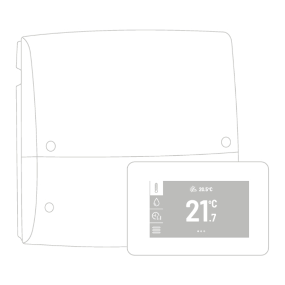
- Page 1 The ecoMAX360I controller for heating and cooling system Additional equipment (optional) OPERATING AND INSTALLATION MANUAL ISSUE: 1.2_EN...
- Page 2 ELECTRIC DEVICE UNDER VOLTAGE! Before any action related to the power supply (cables connection, device installation etc.) check if the controller is not connected to the power mains! Installation should be done by a person with appropriate electrical qualifications. Improper cables connection could result in the controller damage.
-
Page 3: Table Of Contents
TABLE OF CONTENTS RECOMMENDATIONS REGARDING SAFETY ..4 18.2 ......... 39 REVENTION COOLING GENERAL INFORMATION ........5 18.3 ......39 UMP ANTI STANDSTILL FUNCTION INFORMATION ABOUT DOCUMENTATION ..5 ALARMS ............. 40 STORAGE OF DOCUMENTATION ......5 APPLIED SYMBOLS ..........5 DIRECTIVE WEEE 2012/19/UE ...... -
Page 4: Recommendations Regarding Safety
Recommendations regarding safety Use only in heat circulation system Requirements concerning safety are listed in made in accordance with currently particular sections of this instruction. Apart valid regulations. from them it in necessary to fulfill the Electrical system including following requirements. -
Page 5: General Information
General information The ecoMAX360I1 controller is intended for controlling a central heating system and heat source e.g. a gas, oil, pellet boiler and heat pump. Information about documentation Responsibilities after finishing a period of The controller manual is divided into two using product: parts: for user and fitter. -
Page 7: User Settings
USER SETTINGS ecoMAX360I... -
Page 8: The Controller Support
The controller support Domestic hot water. When configuring the controller The controller controls the operation of DHW first time, pump loading a DHW tank up to a user- recommended to use the System defined temperature. Preparation of DHW can configuration assistant in the programmed time intervals. -
Page 9: Circuit Settings
Hysteresis – the circuit will be charged to the preset temperature. After the water temperature in the circuit drops by the value of Hysteresis, the circuit will be switched on again. The parameter is visible only when the circuit is regulated by the thermostat and its operation is enabled. -
Page 10: Time Schedules
DHW work extension – after loading the DHW tank and disabling the DHW pump, a risk of heat pump overheat can occur. In order to cool the heat pump, the operation of DHW pump can be extended by a period of extended operation of DHW pump. -
Page 11: User Settings
Operation mode in order to save heat energy mode resulting from stoppage losses of DHW tank. Preset room temperature is The additional operation mode of the circuit is constant and corresponds to selected by pressing the currently displayed entered Preset symbol on the main screen in the place where temperature value. -
Page 12: Cooperation With The Web Module
ecoNET status - LAN – information on the controller work Wi-Fi Webserver properly, individual room panels www.econet24.com connection status. must have different Wi-Fi settings - configuration of controller subsequent addresses from the Wi-Fi connection, with ecoNET300 module 100…132 pool set. connected. -
Page 13: Cooperation With Additional Devices
7.10 Cooperation with additional devices The controller cooperates with additional system devices, which are optionally offered by the controller manufacturer. Wireless room thermostat. eSTER_x40 Wireless room temperature sensor. eSTER_x20 Room panel with a room thermostat function. It can act as the main control panel. -
Page 15: Installation And Service Settings
INSTALLATION AND SERVICE SETTINGS ecoMAX360I... -
Page 16: Hydraulic Schemes
Hydraulic schemes Basic scheme : 1 – heat source, 2 – heat source pump, 3 – circuit 1 temp. sensor, 4- hydraulic coupling, 5- circuit 1 pump, 6 - circuit 2 pump, 7 – circuit 2 mixer, 8 – circuit 2 temp. sensor, 9 – circuit 2 mixer, 10 – circuit 3 pump, 11 –... - Page 17 Scheme with heat buffer : 1 – heat source, 2 – heat source pump, 3 – circulation pump, 4- controller, 5 – upper buffer temp. sensor, 6 – lower buffer temp. sensor, 7 – circuit 2 and 3 temp. sensor, 8 – circuit 2 and 3 pump, 9 –...
- Page 18 Scheme with heat buffer and HUW tank : 1 – heat source, 2 – heat source pump, 3- circulation pump, 4 – controller, 5 – upper buffer temp. sensor, 6 – lower buffer temp. sensor, 7 – HUW tank temp. sensor, 8 – circuit 2 and 3 temp.
- Page 19 Scheme with heat buffer and HUW tank : 1 – heat source, 2 – heat source pump, 3- circulation pump, 4 – controller, 5 – upper buffer temp. sensor, 6 – lower buffer temp. sensor, 7 – HUW tank temp. sensor, 8 – circuit 2 and 3 temp.
- Page 20 Scheme with one non-adjustable circuit : 1 – heat pump, 2 – controller, 3 – Web module, 4 - 3-way valve, 5 – DHW pump, 6 – DHW tank temp. sensor, 7 – DHW tank, 8 – circulation pump, 9 – circuit 1 pump, 10 –...
- Page 21 Scheme with hydraulic clutch and DHW tank : 1 – heat pump, 2 – controller, 3 – Web module, 4 - 3-way valve, 5 – DHW tank temp. sensor, 6 – DHW tank, 7 – circulation pump, 8 – hydraulic clutch temp. sensor, 9 –...
- Page 22 Scheme with buffer and DHW tank : 1 – heat pump, 2 – controller, 3 – Web module, 4 - 3-way valve, 5 – DHW tank temp. sensor, 6 – DHW tank, 7 – circulation pump, 8 – lower buffer temp. sensor, 9 – upper buffer temp.
- Page 23 Scheme with buffer and DHW tank (cooling function): 1 – heat pump, 2 – controller, 3 – Web module, 4 - 3-way valve, 5 – DHW tank temp. sensor, 6 – DHW tank, 7 – circulation pump, 8 – lower buffer temp. sensor, 9 –...
-
Page 24: Technical Data
Technical data The controller should be installed by a Controller qualified authorized installer, Power supply 230 VAC, 50 Hz accordance with the applicable norms and Current consumption 0,4 A regulations. manufacturer bears Maximum rated current 6 (6) A Protection class IP 20 responsibility for damages caused by failure to Ambient temperature... -
Page 25: Installation Of Module
The controller must not be used as a free-standing device. The controller should be screwed on to the flat surface, e.g. wall. To screw on the controller use mounting holes and proper screws. Location and spacing of mounting holes is Using sharp tool cut out holes in four places of shown in the figure below. -
Page 26: Temperature Sensors Check
CT-10 (NTC 10K) Ambient temp. Rated [°C] [Ω] 33620 20174 12535 8037 5301 3588 2486 1759 Mounting temperature sensor: 1 - pipe, 2 – clamps, 3 - 1270 thermal insulation, 4 - temperature sensor. External temperature sensor. The controller cooperates only with external (weather) temperature sensor type CT6-P. -
Page 27: Connecting The Web Module
recommended to use the control panel as a The ecoNET300 Web module should be room thermostat. Room thermostat or room connected using the ecoLINK2 interface to G2 panel should be assigned to each circuit. socket of the controller. Then enter the menu: User settings →... -
Page 28: Heat Source Output Modulation
In this setup, it is possible to connect a room according to the outside temperature. As a panel which will equalize the inaccuracy of result if the heating curve is appropriate for selecting heating curve, if the selected heating the building, the room temperature remains curve value is too high. -
Page 29: Connecting Electrical System
be equipped with a set of pins control selection ∆ connected to the 230 VAC mains. For safety reasons, the controller must be absolutely connected to 0,5 V the 230 VAC power grid, with the sequence of connecting the phase 1,5 V (L) and neutral (N) wires. -
Page 30: Connecting The Wires
13.1 Connecting the wires Before connecting the wires, remove the terminal cover from the controller’s housing. Disconnect power supply before unscrewing the terminal cover of the controller. Power switch. The controller terminals cover. Cables should be connected to screw terminals of the (5 and 6) connector. The wires should be secured against pulling out using cable clamps (1). -
Page 31: Electrical Scheme
13.2 Electrical scheme Scheme of electrical connections to the controller. L N PE - power supply 230 VAC, H2-S - water temperature sensor of adjustable 2 F1 – main fuse installed inside the controller, circuit type CT-10, H2-M - adjustable 2 circuit servo, H3-S - water temperature sensor of adjustable 3 H3-M - adjustable 3 circuit servo, circuit type CT-10,... -
Page 32: Electric Scheme Addtional Module
Terminals 1-22 are designed to connect devices supplied by the mains 230 VAC voltage. Terminals 23–50 are designed to work with low-voltage devices (< 15 VDC). Connection of the 230 VAC mains voltage to terminals 23-50 or to transmission terminals G1, G2, B results in the regulator damage and poses a threat of electrocution. -
Page 33: Service Menu - Structure
14 Service menu – structure DHW correction temp. Entering the menu requires entering Buffer and circuit correction temp. - service password. Default heating password [0000]. Buffer and circuit correction temp. – When configuring the controller for cooling* the first time, it is recommended to Support min. - Page 34 Circuit cooling* Fixed preset water temperature* Fixed preset water temperature – cooling* Decreasing fixed water temperature Heating curve* Heating curve shift* Minimum temperature Minimum temperature – cooling* Maximum temperature Maximum temperature – cooling* Thermostat Valve opening time Thermostat pump blockade* Mixer input dead zone Proportionality range Constant for integration time...
-
Page 35: Description Of Service Parameters
15 Description of service parameters During the first configuration of the controller has disabled support for all heating circuits, DHW tank, buffer, and circulation pump. Depending on the hydraulic system used, these circuits must be turned Parameters Description The assistant allows you to configure the parameters of the controller the first time you turn on the controller immediately after connecting the central heating system. - Page 36 Pump work extension - boiler pump operation is extension after switching off the main heat source. Pump overrun - time for which to start the circuit pump before turning on the main heat source. This is the time during which only the circuit pump will work. The parameter is available only when the main heat source is a heat pump or an electric boiler.
- Page 37 Settings related to the DHW tank disinfection function. Disinfection is activated from Sunday to Monday at 02:00 am. Note: Users must be informed about activating the function, due to the risk of scalding with hot utility water. Preset temperature – preset DHW tank temperature during disinfection. ...
- Page 38 Fixed preset water temperature - cooling - when Regulation method = Fixed and the cooling function is switching on, main heat source is disabled when Fixed preset water temperature is reached. Parameter is not available if Regulation method = Weather. ...
-
Page 39: Prevention Cooling
16 Replacing components controller’s power supply must disconnected. 16.1 Mains fuse replacement Before starting firmware update all The fuse is located under the controller cover, peripheral devices operating with next to the terminals at high-voltage side. Use the central must be disconnected 230 VAC fuses, anti-surge, made of porcelain: from electric power supply. -
Page 40: Alarms
against immobilization scaling. Therefore, during a break in the use of the controller, the controller power supply should be connected. 19 Alarms The controller reports alarms on the main screen with the symbol. Pressing the symbol will display the list of active alarms. Changes record: The manufacturer reserves a right to make... - Page 41 Installing the module.
- Page 44 Wspólna 19, Ignatki 16-001 Kleosin, Poland plum@plum.pl www.plum.pl www.ecomulti360.com/en/ National Waste Database No. 000009381...
Need help?
Do you have a question about the ecoMAX360I and is the answer not in the manual?
Questions and answers