Table of Contents
Advertisement
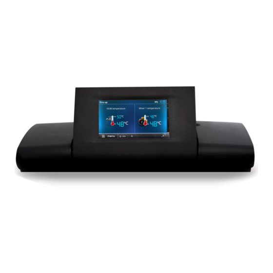
REGULATOR
ecoMAX920P1-K
FOR AUTOMATIC SOLID FUEL FIRED BOILERS
eSTER_x80*
eSTER_x40*
ecoSTER TOUCH*
ecoSTER200*
ecoNET300*
ecoNET.apk
www.econet24.com
* the ecoSTER TOUCH or ecoSTER200 room panel, eSTER_x80 wireless room panel or eSTER_x40
wireless thermostat and ecoNET300 Internet module isn't the standard equipment of the
regulator.
INSTALLATION AND OPERATING MANUAL
ISSUE: 1.3_EN
functions available in the additional
module B
06-2019
Advertisement
Table of Contents

Related Manuals for Plum ecoMAX920P1-K


Summary of Contents for Plum ecoMAX920P1-K
- Page 1 REGULATOR ecoMAX920P1-K FOR AUTOMATIC SOLID FUEL FIRED BOILERS eSTER_x80* eSTER_x40* ecoSTER TOUCH* ecoSTER200* ecoNET300* ecoNET.apk www.econet24.com functions available in the additional module B * the ecoSTER TOUCH or ecoSTER200 room panel, eSTER_x80 wireless room panel or eSTER_x40 wireless thermostat and ecoNET300 Internet module isn’t the standard equipment of the regulator.
- Page 2 ELECTRIC DEVICE UNDER VOLTAGE! Before any action related to the power supply (cables connection, device installation etc.) check if the regulator is not connected to the mains! Installation should be done by a person with appropriate electrical qualifications. Improper cables connection could result in the regulator damage.
-
Page 3: Table Of Contents
TABLE OF CONTENTS 12.10 C ... 29 ONNECTING THE EXHAUST TEMPERATURE SENSOR 12.11 T ......30 EMPERATURE SENSORS CHECKING RECOMMENDATIONS REGARDING SAFETY ..4 12.12 O ......30 PTICAL SENSOR CONNECTION GENERAL INFORMATION ........5 12.13 M .... 30 IXERS ROOM TEMPERATURE CONNECTION 12.14 B .... -
Page 4: Recommendations Regarding Safety
dusts or liquids can cause fire or Recommendations regarding safety explosion. Thus, the regulator should be separated from flammable dusts Requirements concerning safety and gases, e.g. by means of an described in detail in individual chapters of appropriate body. this manual. Apart from them, the following requirements should particular... -
Page 5: General Information
Applied symbols General information In this manual the following graphic symbols The regulator ecoMAX920P1-K is a device are used: designed to control the operation of a boiler - useful information and tips, with automatic feeding of solid fuel with a igniter. -
Page 7: User Settings
USER SETTINGS ecoMAX920P1-K... -
Page 8: User Menu - Structure
Fuel level User menu - structure Alarm level Fuel level calibration Main menu Burner cleaning Information Lambda sensor calibr. * Boiler settings Cleaning intensity HUW settings* Exch. clean start Mixer 1-5 settings* Exch. clean stop Night time decrease Summer/Winter HUW settings* Work schedule... -
Page 9: The Regulator Support
The regulator support preset boiler temperature decrease activated time Buttons description spans, - boiler preset temperature during loading HUW, - boiler preset temperature increase from mixer circulation, - activation of weather control for the boiler circuit, 1. MENU entry buton, active return protection, 2. -
Page 10: Switching On And Off The Boiler
Tip: Fuel level displayed proces is dependand on controller’s settings ecoSTER200, ecoSTER TOUCH and on boiler’s condition before firing up. eSTER_x80, eSTER_x40 room thermostat / Parameters influencing firing up process are panel. in the menu: Service settings → 8.3 Switching On and Off the boiler Burner settings →... -
Page 11: Regulation Modes
Boiler settings → Output modulation 8.7 Regulation modes Can choose between two adjustment modes responsible for stabilizing the boiler preset temperature Standard and Fuzzy Logic. This mode changes in the menu: Boiler settings → Regulation mode Standard mode operation If the boiler’s temperature reach preset one then the controller switches off to the SUPERVISION mode. -
Page 12: Burning Off Mode
SUPERVISION mode controller 8.10 STOP mode oversees furnace, keeping from In the STOP mode the boiler is being burnt burning off. To do so, the burner operates off and awaits the signal to start operation. with very low power, what together with The following can be a signal to start properly adjusted parameters do not cause operation:... -
Page 13: Huw Settings
parameter. parameter Burner and mixers periods, it is required to set the cleaning, in the menu Boiler settings menu, menu: set the time of the burner operation without Summer/Winter → SUMMER mode on cleaning after which the boiler will enter the Summer. -
Page 14: Weather Control
relates adjustements to 20ºC, e.g. for preset Settings mixer without weather room temperature = 22ºC the controller will temp. sensor move heating curve by 2ºC, for preset room required manually desired temperature in mixer’s heating cycle using temperature = 18ºC the controller will move parameter Preset mixer temp., e.g. -
Page 15: Night Decrease Settings Description
Attention: in the process of experimental by controller when it goes beyond scope of adjustement of proper heating curve it is limits of temperatures for given cycle. necessary exlude influence room 8.20 Night decrease settings thermostat on controller work (irrespectively description if room thermostat is connected or not), by n the controller it is possible to set time... -
Page 16: Control Of The Circulation Pump
In the regulator is possible to switch on and switch off the boiler at defined intervals. In the absence of demand for heat, e.g. in summer, one can disable the operation of the boiler at a certain time and thus reduce fuel consumption. -
Page 17: Information
impact on the operation of the burner. The panels - two-way ISM radio transmission. All test is started with the Feeder test parameter panels has a built-in room thermostat. This in the menu: room panels shows useful information such Boiler settings → Feeder as: fuel level, alarm indication etc. -
Page 19: Installation And Service Settings
INSTALLATION AND SERVICE SETTINGS ecoMAX920P1-K... -
Page 20: Hydraulic Schemes
Hydraulic schemes Scheme with 4 way steering valve controlling central heating circuit : 1 – boiler (control panel in the separated version), 2 – regulator, 3 – return temperature sensor, 4 – boiler temperature sensor, 5 – exhaust temperature sensor, 6 – servomotor of 4-way valve, 7 – mixer cycle pump, 8 – mixer cycle temperature sensor, 9 –... - Page 21 Scheme with two adjustable heating circuits and the HUW container : 1 – boiler, 2 – heat exchanger, 3 – regulator, 4 – boiler temperature sensor, 5 – exhaust temperature sensor, 6 – boiler pump, 8 – HUW pump, 9 - mixer valve actuator, 10 – mixer temperature sensor, 11 – mixer pump, 12 – standard room thermostat or ecoSTER TOUCH room panel, eSTER_x40 room thermostat, 13 –...
- Page 22 Scheme with heat buffer : 1 – boiler, 2 – control panel in the separated version, 3 –regulator, 4 – boiler temperature sensor, 5 – exhaust temperature sensor, 6 – boiler pump, 7 – heating buffer, 8 – HUW pump, 9 - mixer valve actuator, 10 –...
-
Page 23: Technical Data
clamp box for the controller version equipped 10 Technical data with STB device. Power supply 230V~, 50Hz 12 Regulator installation Current consumed by regulator 0,04 Maximum rated current 6 (6) A 12.1 Environmental conditions Regulator protection rating IP20 Due to the risk of fire is prohibited to use the Ambient temperature 0...50C controller... -
Page 24: Mounting Of Module
Conditions of enclosing the panel: 1 – panel, 2 – ventilation holes for air circulation (note: the holes cannot decrease required protection rate; ventilation holes not required limiting temperature of the panel surroundings is not exceeded; the ventilation holes do not always guarantee that the temperature of the panel surroundings will be lowered, in such case use other methods) 12.4 Mounting of module... -
Page 25: Ip Protection Rate
cables nominal operating temperature. Terminals 1-22 are designed to connect devices supplied mains 230V~ voltage. Terminals 25–48 are designed to work with low-voltage devices (<12V). Connection of the 230V~ mains voltage to terminals 25-48 or to transmission terminals G2, G3, B and USB results in the regulator damage and poses a threat of electrocution. - Page 26 with a metal protective strip. Unconditionally check if any lead of the insulated cable, or the cable itself don’t have electrical connection with metal grounding strip (which is placed near to high voltage terminals of the regulator). The feeder cable should be connected to the terminals marked with an arrow.
-
Page 27: Electric Scheme
12.7 Electric scheme... - Page 28 23 24 Scheme of electrical connections of the additional B module: M2, M3 – mixer 2 and 3 temp. sensor type CT4, RM2, RM3 – mixer 2 and 3 room thermostat, L N PE - electrical power 230V~, GR – grounding strip, PM2, PM3 –...
-
Page 29: Connection Of Temperature Sensors
12.9 Connecting the weather temp. 12.8 Connection of temperature sensors sensor regulator cooperates only with The regulator cooperates only with a weather temperature sensors of the CT4 type. The temp. sensor of the CT6-P type. The sensor use of other types of temp. sensors is should be installed on the coolest wall of the prohibited. -
Page 30: Temperature Sensors Checking
CT6-P (weather) Temp. Min. Nom. Max. °C Ω Ω Ω 901,6 901,9 902,2 921,3 921,6 921,9 960,6 960,9 961,2 999,7 1000,0 1000,3 1096,9 1097,3 1097,7 1193,4 1194,0 1194,6 1384,2 1385,0 1385,8 1478,5 1479,4 1480,3 1572,0 1573,1 1574,2 CT2S-2 (exhaust) Temp. Min. -
Page 31: Reserve Boiler Connection
T1 (if the ecoSTER TOUCH or eSTER_x80 Deactivating control over additional boiler is room control panel is connected): done after setting zero value of switching off for this parameter. Service settings → Boiler settings → Controlling extension of the boiler Thermostat select. -
Page 32: Mixer Connection
controller report alarms Activate the controller and select in activating external devices like ring or GSM service menu proper Mixer support: device to short messages SMS sending. Service settings Mixer 1 settings Alarm signaling device must be connected ... -
Page 33: Connecting Temperature Limiter
cover into AUTO. Connect the electrical description of the wireless panels' operation power to the controller - % indicator of valve is given in the appropriate operating manual opening is calibrated. dedicated to these devices. During calibration, the servo is closed by the valve opening time. -
Page 34: Service Menu - Structure
Grate * 13 Service menu - structure Flush time Superv. Flush period Sup. Service settings Auto switch to pellet Burner settings Lambda sensor* Boiler settings Lambda mode CH and HUW settings Dynamics Buffer settings* Response time Mixer settings 1-5* ... - Page 35 Max. mixer temp. Proportional range Integration time constant Valve opening time Pump off by therm. Mixer input dead zone * Output H Exchanger cleaning Exch. clean. time Exch. clean. pause Alarm Reserve boiler * not available if proper sensor not attached, extension module or parameter is hidden.
-
Page 36: Description Of Service Settings
14 Description of service settings 14.1 Burner Parameter Description Firing-up Time to check whether the burner is already firing up. Only fan is operating. If the flame has sufficient brightness, it switches to the OERATION mode without the BURNING OFF Ignition test time mode. -
Page 37: Boiler
Air flush interval Break between airflows while burning off the fuel in burning off process. Air flush start Flame brightness with which airflow starts while burning off the fuel. Flame brightness with which airflow starts when burning off the fuel in burning off ... -
Page 38: And Huw
ecoSTER T2 - option available after connecting room panel, boiler operation is dependant on room thermostat No 2 in ecoSTER – on sensor CT7, ecoSTER T3 - option available after connecting room panel, boiler operation is dependant on room thermostat No3 in ecoSTER200 – on sensor CT7, ... -
Page 39: Buffer
Available after connecting HUW sensor. After feeding HUW container and deactivating HUW pump may be a risk of boiler overheating. It happens in case when preset HW HUW operation extension temperature was higher than boiler preset temperature. This issue is exceptionally important in HUW pump operation in SUMMER mode, when pump is deactivated. -
Page 40: Other Parameters
The proper values is set experimentally. It is recommended to set this parameter in the range of 2..6. The greater the value of this parameter, the slower is the actuator reaction for temperature deviation. Setting too lower values can lead to unnecessary actuator Integr. -
Page 41: Alarms Descriptions
Alarm appears by boiler sensor damage and 15 Alarms descriptions by exceeding measuring scope of this sensor. Alarm numbers displayed on the wireless When alarm appears the boiler is activated. room thermostat. The sensor is to be checked and replaced if Boiler max. -
Page 42: Unsuccessful Boiler Firing-Up Attempt
will then be deactivated. After the boiler In case of power stoppage the controller temperature will drop down it is required to returns to operation mode in which it was unscrew an oval STB lid and then press the before stoppage. Reset button. -
Page 43: The Regulator Configuration By Boiler
Default settings for given boilers / burners should be consulted with Company Plum Sp. z o. o. In order to load new parameters go to: Service settings → [special password] and choose proper boiler/burner. Default settings can also be loaded by special software provided by Company Plum Sp. -
Page 44: Possible Faults Description
19 Possible faults description Symptoms Tips Check: There are no signs of operation of If line fuses are not blown, replace if necessary. device despite connection to the If the wire connecting panel with the executive module is plugged correctly and if network. - Page 48 Wspólna 19, Ignatki 16-001 Kleosin Poland plum@plum.pl www.pum.pl...
Need help?
Do you have a question about the ecoMAX920P1-K and is the answer not in the manual?
Questions and answers