Ruijie Reyee RG-RAP6262 Hardware Installation And Reference Manual
Hide thumbs
Also See for Reyee RG-RAP6262:
- Hardware installation and reference manual (19 pages) ,
- Configuration manual (219 pages) ,
- Cookbook (121 pages)

Related Manuals for Ruijie Reyee RG-RAP6262


Summary of Contents for Ruijie Reyee RG-RAP6262
- Page 1 Ruijie Reyee RG-RAP6262 Access Point Hardware Installation and Reference Guide Document Version: V1.1 Date: 2023-03-02 Copyright © 2023 Ruijie Networks...
- Page 2 All rights are reserved in this document and this statement. Any reproduction, excerption, backup, modification, transmission, translation or commercial use of this document or any portion of this document, in any form or by any means, without the prior written consent of Ruijie Networks is prohibited.
-
Page 3: Preface
Intended Audience This document is intended for: Network engineers Technical support and servicing engineers Network administrators Technical Support Official website of Ruijie Reyee: https://www.ruijienetworks.com/products/reyee Technical Support Website: https://ruijienetworks.com/support Case Portal: https://caseportal.ruijienetworks.com Community: https://community.ruijienetworks.com ... - Page 4 Specification An alert that contains a description of product or version support. Note This manual provides the device installation steps, hardware troubleshooting, module technical specifications, and specifications and usage guidelines for cables and connectors. It is intended for the users who have some experience in installing and maintaining network hardware.
-
Page 5: Table Of Contents
Contents Preface ..............................I 1 Product Overview ..........................1 1.1 About the RG-RAP6262 Access Point ..................1 1.2 Package Contents........................1 1.3 Hardware Features ........................2 1.3.1 Access Point........................2 1.3.2 Ports and RESET Hole ....................3 1.4 Technical Specifications ......................3 1.5 Power Specifications ......................... - Page 6 3.1 Installation Procedure ......................10 3.2 Before You Begin ........................10 3.3 Precautions ..........................11 3.4 Installing the Access Point ....................... 11 3.4.1 Wall Mount ........................11 3.4.2 Vertical Pole Mount ...................... 12 3.4.3 Horizontal Pole Mount....................13 3.5 Installing the Cables ........................ 13 3.5.1 Installing the Ethernet Cable ..................
- Page 7 7.1 Connectors and Media ......................23 7.1.1 1000BASE-T/100BASE-TX/10BASE-T Port..............23 7.1.2 Fiber-Optic Cable Connection ..................24 7.2 Mini-GBIC Modules ........................25 7.3 Cabling ............................. 27...
-
Page 8: Product Overview
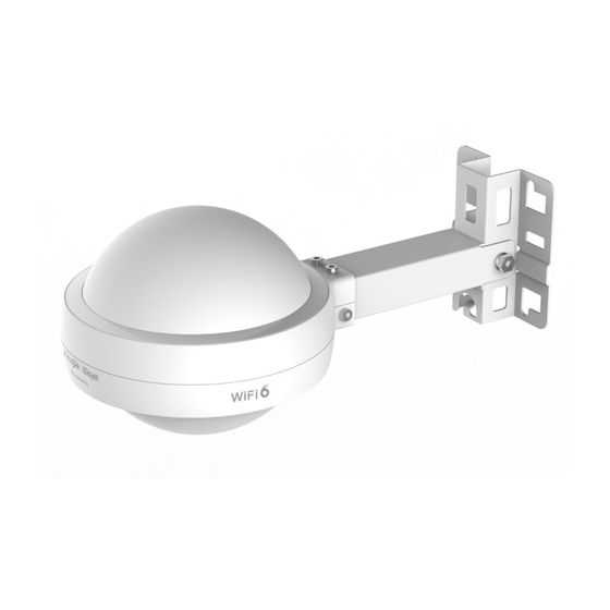
About the RG-RAP6262 Access Point The RG-RAP6262 is a dual-radio access point designed for outdoor scenarios by Ruijie Networks. Compliant with the IEEE 802.11ax standard, the access point can work in the 2.4 GHz and 5 GHz bands at the same time. -
Page 9: Hardware Features
Hardware Installation and Reference Guide Product Overview Hardware Features 1.3.1 Access Point Figure 1-1 Access Point Note CMIIT ID is printed on the device nameplate. Table 1-2 Status Description Flashing Data is transmitted by Wi-Fi. Wi-Fi LED (Green) Solid on Wi-Fi is enabled and no data is transmitted. -
Page 10: Ports And Reset Hole
Hardware Installation and Reference Guide Product Overview No link is detected for the port. Flashing The port has made a successful link and is sending/receiving traffic. SFP Port Status Solid on The port has made a successful link and is not LED (Green) sending/receiving traffic. - Page 11 Hardware Installation and Reference Guide Product Overview Standard & Protocol 802.11ax, 802.11ac wave2/wave1 and 802.11a/b/g/n Operating Radio 802.11b/g/n/ax: 2.4 GHz to 2.4835 GHz 802.11a/n/ac/ax: 5.150 GHz to 5.350 GHz, 5.470 GHz to 5.725 GHz, 5.725 GHz to 5.850 GHz Antenna 2.4 GHz: two spatial streams, 2 x 2 MIMO 5 GHz: two spatial streams, 2 x 2 MIMO Max Transmit Rate...
-
Page 12: Power Specifications
Power Specifications The access point can be powered by either DC or PoE power supply. In a DC power supply scenario, use a Ruijie 12 V DC/2 A power adapter. The adapter should be purchased separately. In a PoE power supply scenario, connect one end of the Ethernet cable to the LAN/PoE port of the access point, and connect the other end to a port of a PoE-capable switch or a PoE device. -
Page 13: Heat Dissipation
Hardware Installation and Reference Guide Product Overview Heat Dissipation The RG-RAP6262 adopts a fanless design. Maintain a sufficient clearance around the access point for proper ventilation. -
Page 14: Preparing For Installation
Hardware Installation and Reference Guide Preparing for Installation Preparing for Installation Safety Precautions Note ● To avoid personal injury and device damage, carefully read the safety precautions before you install the access point. ● The following safety precautions may not cover all possible dangers. 2.1.1 General Safety Precautions ... -
Page 15: Installation Environment Requirements
Hardware Installation and Reference Guide Preparing for Installation Warning ● Any nonstandard or inaccurate electrical operation can cause accidents such as fires or electrical attacks, thus causing severe, or even fatal damages to human bodies and the devices. ● Direct or indirect touch through a wet object on high-voltage and mains supply can bring a fatal danger. Installation Environment Requirements 2.2.1 Site Requirements... -
Page 16: Emi Requirements
Hardware Installation and Reference Guide Preparing for Installation Seal the reset hole and the DC connector with the waterproof caps. The cable glands must be used for all cables that are threaded through the ports to prevent exposing the access point interior to environmental elements. -
Page 17: Installing The Access Point
Hardware Installation and Reference Guide Installing the Access Point Installing the Access Point The RG-RAP6262 access point must be installed outdoors. Caution Please ensure that you have carefully read Chapter 2 and that the requirements in Chapter 2 are all met. Installation Procedure Start Prepare for Installation... -
Page 18: Precautions
Hardware Installation and Reference Guide Installing the Access Point Precautions The outdoor access point can be mounted on a wall or a pole with a diameter ranging from 50 mm to 70 mm (1.97 in. to 2.76 in.). If the diameter of the pole is out of this range, please prepare a hose clamp that can hold the pole. -
Page 19: Vertical Pole Mount
Hardware Installation and Reference Guide Installing the Access Point Figure 3-2 Securing the Mounting Plate on the Wall (3) Install the access point and the mounting arm to the mounting plate and secure them with M8 x 20 screws. Figure 3-3 Mounting the Access Point 3.4.2 Vertical Pole Mount... -
Page 20: Horizontal Pole Mount
Hardware Installation and Reference Guide Installing the Access Point Figure 3-5 Mounting the Access Point 3.4.3 Horizontal Pole Mount (1) Secure the mounting plate to a horizontal pole by threading two hose clamps through the square holes of the mounting plate. Tighten the screws using a Philips screwdriver. Figure 3-6 Securing the Mounting Plate on a Horizontal Pole (2) Install the access point and the mounting arm to the mounting plate using M8 x 20 screws. -
Page 21: Installing The Fiber-Optic Cable
Hardware Installation and Reference Guide Installing the Access Point (1) Trim an Ethernet cable according to the distance between the access point and the power supply. (2) Insert the unterminated end of the Ethernet cable through part D, C and B in sequence. Figure 3-8 Exploded View of Cable Gland Assembly Washer (Rubber... - Page 22 Hardware Installation and Reference Guide Installing the Access Point (2) Open the top cover and use the 5 mm Allen key to loosen the screw on the hinge pin. Remove the cables from the trough of the mounting arm and rotate the main unit by 90 degrees clockwise. Use the flat-blade screwdriver to loosen the SFP port plug and insert a SFP transceiver (customer-supplied) into the port.
- Page 23 Hardware Installation and Reference Guide Installing the Access Point connector into the SFP port of the access point. Thread A (adapter base) into the SFP port. Slide B (split gasket) and C (grommet) along the cable, pressing firmly to seat B (gasket) completely into C (grommet). Tighten D (compression cap) until C (grommet) and B (gasket) compress on to the cable and provide cable strain relief.
- Page 24 Hardware Installation and Reference Guide Installing the Access Point Figure 3-13 Closing the Top Cover Installing the Cover on the Mounting Arm Make sure to seal the DC connector not in use and the reset hole with clean weatherproof caps (a). If you want to install the cable gland without an Ethernet cable threaded through it, insert the waterproof rubber rod (b) into the washer (rubber gasket), and tighten all parts properly.
-
Page 25: Bundling Cables
Hardware Installation and Reference Guide Installing the Access Point Note: To avoid damage to the cover of the mounting arm, hold the retention clips on the cover open to remove the cover. Bundling Cables Caution ● The power cords and other cables should be bound in a visually pleasing way. ●... -
Page 26: Checking After Installation
Hardware Installation and Reference Guide Installing the Access Point Checking after Installation (1) Checking the Access Point Verify that the external power supply matches with the requirement of the access point. Verify that the access point and cables are securely fastened. (2) Checking Cable Connection ... -
Page 27: Verifying Operating Status
Hardware Installation and Reference Guide Verifying Operating Status Verifying Operating Status Setting up Configuration Environment The access point can be powered by PoE or local power adapter. When the access point is powered by a power adapter or PoE, verify that the power supply functions properly and meets safety requirements. -
Page 28: Monitoring And Maintenance
Hardware Installation and Reference Guide Monitoring and Maintenance Monitoring and Maintenance Monitoring You can observe the LED color to monitor the access point status. Hardware Maintenance If the hardware is faulty, please contact technical support. -
Page 29: Common Troubleshooting
Check whether the LED is normal. Check whether cables are properly connected with ports. Contact Ruijie technical support to check whether hardware faults exist. Common Faults The status LED is still off after the access point is powered on. -
Page 30: Appendix
Hardware Installation and Reference Guide Appendix Appendix Connectors and Media 7.1.1 1000BASE-T/100BASE-TX/10BASE-T Port 1000BASE-T/100BASE-TX/10BASE-T is a 10/100/1000 Mbps self-adaptive port that supports auto MDI/MDIX Crossover. Compliant with IEEE 802.3ab, 1000BASE-T requires Category 5e 100-ohm UTP or STP (STP is recommended) with a maximum distance of 100 meters (328.08 feet). -
Page 31: Fiber-Optic Cable Connection
Hardware Installation and Reference Guide Appendix The following figure shows feasible connections of the straight-through and crossover twisted pairs for a 100BASE- TX/10BASE-T port. Figure 7-3 100BASE-TX/10BASE-T Connection 7.1.2 Fiber-Optic Cable Connection You can choose single-mode or multi-mode fiber-optic cables according to the SFP transceiver types. The following figure shows connection of fiber-optic cables. -
Page 32: Mini-Gbic Modules
Hardware Installation and Reference Guide Appendix Mini-GBIC Modules We provide different GE SFP transceivers (Mini-GBIC modules). You can select a model to suit your specific needs. Table 7-1 Mini-GBIC Modules Core Max Tx Max Rx Fiber Mini- Cable Size (MHz/ Intensity Sensitivity GBIC... - Page 33 Hardware Installation and Reference Guide Appendix Mini- GBIC- 100 m Warning For Mini-GBIC modules with a cabling distance of over 40 km (including 40 km), install an attenuator to avoid overload when using short single-mode fiber-optic cables.
-
Page 34: Cabling
Hardware Installation and Reference Guide Appendix Cabling During installation, route cable bundles upward or downward along the sides of the rack depending on the actual situation in the equipment room. All cable connectors used for transit should be placed at the bottom of the cabinet rather than be exposed outside of the cabinet. - Page 35 Hardware Installation and Reference Guide Appendix After bundling up cables with cable ties, cut off the remaining part. The cut should be smooth and trim, without sharp corners. Figure 7-6 Bundling up Cables When cables need to be bent, you should first bundle them up. However, the buckle cannot be bundled within the bend area.
- Page 36 Hardware Installation and Reference Guide Appendix Figure 7-8 Cable Fastening Flat Washer Spring Washer Flat Washer Hard power cords should be fastened in the terminal connection area to prevent stress on terminal connection and cable. Do not use self-tapping screws to fasten terminals. ...
Need help?
Do you have a question about the Reyee RG-RAP6262 and is the answer not in the manual?
Questions and answers