Table of Contents
Advertisement
Quick Links
CAUTION
For Safe Operation
Read Rules And
Instructions Carefully
Safety Instructions
Tractor Preparation
Operating Instructions
Assembly & Mounting
Maintenance
RHINO
®
1020 S. Sangamon Ave.
Gibson City, IL 60936
800-446-5158
Email: parts@servis-rhino.com
Published 02/13
Model 240P
Post Hole Digger
Operator's Manual
Part No. 00788394
Advertisement
Table of Contents

Related Manuals for RHINO 240P


Summary of Contents for RHINO 240P
- Page 1 Model 240P Post Hole Digger Operator’s Manual CAUTION For Safe Operation Read Rules And Instructions Carefully Safety Instructions Tractor Preparation Operating Instructions Assembly & Mounting Maintenance RHINO ® 1020 S. Sangamon Ave. Gibson City, IL 60936 800-446-5158 Email: parts@servis-rhino.com Published 02/13...
- Page 2 CONGRATULATIONS!
-
Page 3: Table Of Contents
240P Post Hole Digger Operator’s Manual TABLE OF CONTENTS WARRANTY INFORMATION ....... . . 2-3 DEALER CHECKLIST . -
Page 4: Warranty Information
Like all mechanical products, it will require cleaning and upkeep. Use only genuine RHINO service parts. Substitute parts will void the warranty and may not meet stan- dards required for safe and satisfactory operation. Record the model and serial number of your... -
Page 6: Dealer Checklist
DEALER PREPARATION CHECK LIST Post Hole Diggers BEFORE DELIVERING MACHINE – The following check list should be completed. Use the Operator’s Manual as a guide. ❑ Assembly completed ❑ Gearbox filled to proper level with oil ❑ Driveline shields are in place with no damage ❑... -
Page 7: Federal Laws And Regulations
SAFETY PHD 01/13 Safety Section... -
Page 8: Important Safety Information
To the Owner/Operator/Dealer All implements with moving parts are potentially hazardous. There is no substitute for a cautious, safe-minded opera- tor who recognizes the potential hazards and follows reasonable safety practices. The manufacturer has designed this implement to be used with all its safety equipment properly attached to minimize the chance of accidents. BEFORE YOU START!! Read the safety messages on the implement and shown in your manual. -
Page 9: Personal Protective Equipment
SAFETY INSTRUCTIONS (continued) EQUIPMENT SAFETY GUIDELINES Safety of the operator is one of the main concerns in designing and developing a new piece of equipment. Designers and manufacturers build in as many safety features as possible. However, every year many accidents occur which could have been avoided by a few seconds of thought and a more careful approach to handling equipment. -
Page 10: Operating Safety
SAFETY INSTRUCTIONS (continued) OPERATIONAL SAFETY Start tractor only when properly seated in the tractor seat. Starting a tractor in gear can result in injury or death. Do not mount or dismount the tractor while the tractor is moving. Mount or dismount the tractor only when the tractor and all moving parts are completely stopped. - Page 11 SAFETY INSTRUCTIONS (continued) OPERATIONAL SAFETY (continued) This digger is designed for use only on tractors with 540 RPM power take off. Do not operate the post hole digger near existing fence wire. Fencing wire, loose wire, cable, landscape webbing or other similar debris can become entangled in the auger and be rapidly pulled into the auger along with bystanders in contact with the material.
-
Page 12: Repair And Maintenance Safety
SAFETY INSTRUCTIONS (continued) OPERATIONAL SAFETY (continued) Inspect the entire machine periodically as indicated in the Maintenance Section of this manual. Look for loose fasteners, worn or broken parts, pinched hydraulic hoses, and leaky or loose fittings. Make sure all pins have cotter pins and washers. - Page 13 SAFETY INSTRUCTIONS (continued) MAINTENANCE SAFETY (continued) Keep all persons away from operator control area while performing adjustments, service, or maintenance. Periodically tighten all bolts, nuts and screws and check that all cotter pins are properly installed to ensure unit is in a safe condition. When completing a maintenance or service function, make sure all safety shields and devices are installed before placing unit in service.
- Page 14 SAFETY INSTRUCTIONS (continued) TRANSPORT SAFETY (continued) Be aware of the operating conditions. Do not operate the tractor with weak or faulty brakes. When operating down a hill or on wet or rain slick roads, the braking distance increases; use extreme care and reduce your speed in these conditions.
-
Page 15: Safety Decals
SAFETY INSTRUCTIONS (continued) SAFETY SIGNS Keep safety signs clean and legible at all times. Replace safety signs that are missing or have become illegible. Replaced parts that displayed a safety sign should also display the current sign. Safety signs are available from your Distributor or Dealer Parts Department or the factory. How to Install Safety Signs: Be sure that the installation area is clean and dry. - Page 16 SAFETY SIGNS AND DECALS (continued) 101358 BOTH OF ABOVE LOCATED ON POST HOLE DIGGER BOOM LOCATED ON POST HOLE DIGGER BOOM LOCATED AT TOP OF AUGER CENTER TUBE REMEMBER: If Safety Signs have been damaged, removed, become illegible or parts replaced without Signs, new Safety Signs must be applied.
-
Page 17: Intended Use
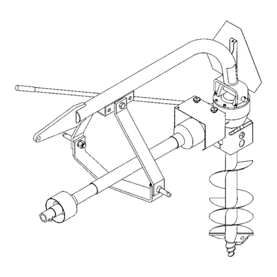
Refer to the “exploded view” of the post hole digger on page 24 of this manual. Become familiar with the relation- The Model 240P 3-pt. mounted post hole digger will fit ship of the various components and parts shown. most Category I, Category II and some larger Category 0 tractors equipped with a standard 3-pt. - Page 18 INSTRUCTIONS (continued) Clean and check the input shaft of the gearbox. If any WARNING nicks or dents have occurred in shipping, lightly file to remove and make the shaft smooth. Do not install a longer shear bolt or other longer Install the input guard backplate (Ref.
- Page 19 INSTRUCTIONS (continued) PREPARATION PROCEDURE WARNING • Thoroughly read and understand your Operator’s When attaching PTO yoke to tractor PTO shaft, it is Manuals. important that spring-activated locking pin or balls operate freely and are seated in groove on PTO shaft. •...
-
Page 20: Operating Instructions
OPERATING INSTRUCTIONS PRE-OPERATION CHECKLIST • In some types of soil, it may be necessary to hold back against the auger screw action by moving the hydraulic control lever to “HOLD” or “RAISE” position (OPERATOR RESPONSIBILITY) to keep the auger from screwing into the ground. ____ Review and follow safety rules and safety signs on pages 5 through 14. - Page 21 OPERATION INSTRUCTIONS (continued) NOTE: Be sure auger is completely retracted from WARNING the hole before attempting to move the tractor. ■ Never locate auger by putting hands on auger, gearbox, or boom when there is any sign of rotation Once the auger is digging a hole, the tractor cannot be on the driveline or auger or if the tractor is running.
- Page 22 Post hole diggers when off the tractor, can be an awkward piece of equipment to handle. NOTE: Never exceed the recommended auger capacity of the post hole digger. The Model 240P Always shut the tractor completely down, place the standard duty digger is designed for use with augers transmission in park, disengage the PTO and set the up to 12-inch diameter.
-
Page 23: General Maintenance
OWNER SERVICE The information in this section is written for operators LUBRICATION CHART who possess basic mechanical skills. Should you need REF NO. DESCRIPTION FREQUENCY help, your dealer has trained service technicians Front U-Joint 8 Hrs. available. For your protection, read and follow all safety Rear U-Joint 8 Hrs. -
Page 24: Trouble-Shooting Guide
TROUBLE-SHOOTING GUIDE PROBLEM POSSIBLE CAUSE POSSIBLE REMEDY Auger will not dig. 1. Shear bolt sheared. Install new Grade 2 shear bolt. 2. Teeth dull. Sharpen or replace teeth. 3. Ground too dry and hard. Order optional down force kit, or wait until it rains. (May have to replace center point.) 4. - Page 25 TROUBLE-SHOOTING GUIDE (continued) PROBLEM POSSIBLE CAUSE POSSIBLE REMEDY Driveline is dam- 1. Raising auger too high with PTO engaged caus- Stop driveline rotation before raising auger too high. ing excessive joint operating angle. aged. 2. Auger swings while moving from hole to hole Always disengage PTO before moving tractor.
-
Page 26: Parts Breakdown Illustration
MODEL 240P POST HOLE DIGGER ILLUSTRATION... -
Page 27: Auger Breakdown Illustration
AUGER PARTS ILLUSTRATION AUGER TEETH MOUNTING PATTERNS (Regular Duty Augers) -
Page 28: Hydraulic Down Force Kit
DOWN FORCE KIT INSTRUCTIONS KIT #50072109 (FOR MODEL 240P POST HOLE DIGGER) INSTALLATION OPERATION 1. Refer to the parts illustration and install the Down Lower the Post Hole Digger in the usual manner and Force Kit parts as shown. The pin attaching the boom allow the auger to dig. -
Page 29: Optional Parking Stand
OPTIONAL PARKING STAND KIT #50072108 (FOR MODEL 240P POST HOLE DIGGER) 1. Remove auger from digger. 2. Remove hardware (5 & 6) and output shield (7) from bottom of gearbox. 3. Place parking stand base plate (4) and output shield (7) over the output shaft. -
Page 30: Torque Specifications
PROPER TORQUE FOR FASTENERS... -
Page 31: Specifications
SPECIFICATIONS MODEL 240P Tractor Category Compact, Category 1 and Category 2 Gearbox Special alloy pinion gears and tapered roller bearings – 3:1 ration. Gears Heat-treated to Rockwell C30-40 to a depth of .030-.040 Driveline Equipped with quick-tach yoke to fit standard 6-spine PTO (completely shielded) Cutting Edges Sold separately. - Page 32 TO THE OWNER / OPERATOR / DEALER 240P - 02/13 P/N 00788394 Printed U.S.A.
Need help?
Do you have a question about the 240P and is the answer not in the manual?
Questions and answers