
Related Manuals for RHINO Ranch Pro


Summary of Contents for RHINO Ranch Pro
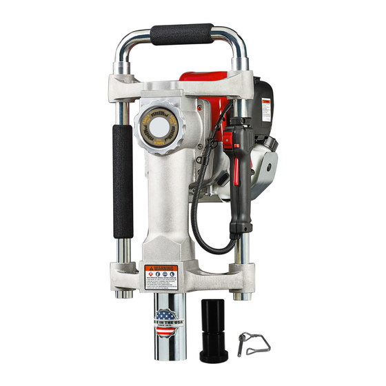
- Page 1 224975 Highest Quality Post Drivers and Post Pullers Ranch Pro ™ Gas Powered Driver P/N: 300001 O W N E R S M A N U A L Effective Serial No.: 002270 Form No. 300800-09/2015...
- Page 2 TAKE SAFETY SERIOUSLY Your safety, and the safety of others, is very important. The proper and safe use of your Rhino post ® driver is an important responsibility and should be taken seriously. This owner’s manual contains important safety information. Please read it carefully. The information and specifications included in this publication were in effect at the time of approval for printing.
-
Page 3: Table Of Contents
Servicing Crankshaft and Piston .........................11 Service of the Hammer and Anvil ....................... 12 Ranch Pro Parts List ..........................16 ™ Limited Warranty and Registration ......................20 Troubleshooting ............................21 © 2012, 2015 Rhino Tool Company Inc., - All Rights Reserved... -
Page 4: Introduction
Honda engine. Please ing dealer is dedicated to your satisfaction, and will be pleased to read this manual as closely as you do the Rhino manual. The answer your questions and concerns. success that you experience with this tool is dependent upon your... -
Page 5: Post Driver Safety
POST DRIVER SAFETY IMPORTANT SAFETY INFORMATION The Rhino Ranch Pro gas powered you are aware of all underground utilities California to cause cancer, birth defects or ® ™ driver is designed to drive fence posts, in the area in which you intend to drive other reproductive harm. - Page 6 Misuse may result in personal injury or in the presence of this power tool during property damage, including damage to the operation. If not wearing protective gear, • Ranch Pro has been designed with ™ machine. bystanders should keep a distance of 20...
- Page 7 Overall 13 x 14 x 20.5 in. DANGER tion of their hands and fingers. If any of ately. Simply contact your Rhino Tool Dimensions (330 x 355 x 528 mm) NOTE the above symptoms appear, seek medical...
- Page 8 Ranch Pro will give driver should also be inspected for any de- ® ™ fects. Do not use the Ranch Pro if there you many years of trouble free service. ™ IMPORTANT is any damage or wear until the damage or You must read and understand your post wear is corrected and repaired.
-
Page 9: Ranch Pro ™ Operating Instructions
DANGER Ranch Pro Operating Instructions... continued ™ WARNING To start a COLD engine, move the choke Slide thumb switch on throttle handle engine. Return it gently to prevent DANGER lever to the CLOSED position (Fig. 3). down or into the ON position. -
Page 10: Starting The Engine
(Fig 6). (See Exhaust Warning) by slightly depressing the trigger and then driver to the OFF position. immediately releasing it. Use caution as to Insert a post into the Ranch Pro making ™ 2. Move the choke lever to the OPEN not engage the clutch. - Page 11 (25.4mm) adapter. Installing a Chuck Adapter To help insure years of operation, wipe Maintenance of the Ranch Pro ™ down the Ranch Pro with a clean cloth ™ (Fig. 8) For driving up to 3/4" (19mm) NEVER REFUEL after each days use.
-
Page 12: Ranch Pro ™ Maintenance
The following state, and federal regulations. state, and federal regulations. instructions are for the Rhino Ranch Pro ® ™ 2. Replace air cleaner elements. This specifically with general instructions for 2. -
Page 13: Ranch Pro ™ Service Instructions
Ranch Pro Service Instructions... continued ™ WRENCHES TO LOOSEN THE COV- 4. Remove and service the hammer and Use only Rhino Pro Series Grease (p/n ER AS IT MAY CAUSE DAMAGE TO anvil. See page 12 for instructions. 300500.) WARNING THE DRIVER. -
Page 14: Service Of The Hammer And Anvil
Ranch Pro Service Instructions... continued Rotate crankshaft with connecting rod, and inch/pounds (Nm), and threadlocker. from the opposite side. When the parts crankpin until the crank pin is in the 12:00 are removed, note the order and disas- Remove the four (4) bolts (p/n 300702-4) o'clock position. - Page 15 Fig. 14. Clean and well socket. damaged parts. Lubricate the cylinder, inspect the hammer for damage or exces- piston, and connecting rod with Rhino ap- THE CRANK PIN CAUTION sive wear. The hammer o-ring Seal should proved grease (p/n 300500.)
- Page 16 Fig. 16 grease has been completely removed add tube o-ring onto the chuck tube. It should and assemble into the anvil o-ring cup. 2.75 oz or 81.32 ml of Rhino Pro Series ® Grease or until level with the bottom of the crankpin head.
- Page 17 Ranch Pro Service Instructions... continued ™ look like Fig. 12 on page 12. seated on the post driver body. Check for any misalignment or binding when joining Remove the handle tubes (p/n 301232) the parts. DO NOT USE EXCESSIVE from the handle cups and remove and FORCE.
-
Page 18: Ranch Pro ™ Parts List
Rhino Ranch Pro Parts List ® ™... - Page 19 300606 Anvil O-ring 301221-2 Handle Collar (2 Qty.) 300608 Chuck Tube O-ring Seal 610010-4 Handle Anti-Vibration Spring (4 Qty.) 300156 Ranch Pro Chuck Tube 300214 Top Handle Bracket 300031 Lower Driver Body 300075 Piston and Connecting Rod Assembly 300702-4 Lower Body Bolts (4 Qty.)
- Page 20 Rhino Ranch Pro Driver Parts List ...continued ® ™...
- Page 21 Crankcase Bolts (6 per driver) 300500 Rhino Pro Series Grease ® 300040 Crankshaft 300505 Service Kit for Ranch Pro 300782-2 Retaining Ring for Crankshaft & Clutch Drum with Pinion Gear (4 per driver) Bolt Torque Specifications 300200 Gear 300715-4 Top Handle Bolt Set – 132.0 in/lbs (14.91 Nm)
- Page 22 (12) months with regard to all other components, NO BE LIABLE FOR ANY LOSS OF BUSINESS, REVENUES, excluding the Honda GX35 engine for which Rhino provides no OR PROFIT OR OTHER INDIRECT, INCIDENTAL, SPECIAL OR warranty and for which the warranty provided by American Honda CONSEQUENTIAL DAMAGES OR LOSS ARISING OUT OF ANY Motor Co., Inc.
-
Page 23: Troubleshooting
This will position the driver on an angle with the top handle at the topmost point. Have your serial number handy and contact Rhino Tool Company. Phone: 309.853.5555 or Toll Free 866-707-1808, Other problems Fax:309.856.5905, Email: info@rhinotool.com. - Page 24 Manufacturing Quality Post Drivers and Post Pullers Since 1975 Rhino Tool Company, Inc. 620 Andrews Avenue Kewanee, IL 61443 P: 309.853.5555 or Toll Free 866-707-1808 F:309.856.5905 © 2012, 2015 Rhino Tool Company, Inc. www.rhinotool.com E: info@rhinotool.com...
Need help?
Do you have a question about the Ranch Pro and is the answer not in the manual?
Questions and answers