Table of Contents
Advertisement
Quick Links
KIT_T2G-B-H_LITE user guide
About this document
Scope and purpose
This document serves as a guide for using the KIT_T2G-B-H_LITE. This document explains the kit operation,
describes the out-of-the-box (OOB) example and its operation, and the hardware details of the board.
Intended audience
This document is intended for TRAVEO™ T2G Body High Lite evaluation kit users.
Reference documents
This user guide should be read in conjunction with the following documents:
AN235305 - Getting started with TRAVEO™ T2G family MCUs in ModusToolbox™
•
TRAVEO™ T2G Body High datasheet
•
User Guide
Please read the "Important notice" and "Warnings" at the end of this document
www.infineon.com
002-37237 Rev. **
2023-07-20
Advertisement
Table of Contents

Related Manuals for Infineon KIT T2G-B-H LITE


Summary of Contents for Infineon KIT T2G-B-H LITE
-
Page 1: About This Document
This user guide should be read in conjunction with the following documents: AN235305 - Getting started with TRAVEO™ T2G family MCUs in ModusToolbox™ • TRAVEO™ T2G Body High datasheet • User Guide Please read the “Important notice” and “Warnings” at the end of this document 002-37237 Rev. ** www.infineon.com 2023-07-20... -
Page 2: Table Of Contents
KIT_T2G-B-H_LITE user guide Table of contents Table of contents About this document ........................1 Table of contents ..........................2 Safety and regulatory compliance information .................. 3 General safety instructions ......................3 Introduction .......................... 4 Getting started............................4 Additional learning resources ......................... 5 Technical support............................ -
Page 3: Safety And Regulatory Compliance Information
General safety instructions ESD protection ESD can damage boards and associated components. Infineon recommends that you perform procedures only at an ESD workstation. If an ESD workstation is unavailable, use appropriate ESD protection by wearing an anti- static wrist strap attached to the chassis ground (any unpainted metal surface) on your board when handling parts. -
Page 4: Introduction
There is a wide range of code examples to evaluate the KIT_T2G-B-H_LITE. These examples help you • familiarize TRAVEO™ T2G-B-H MCU and create your own design. These examples can be accessed through the ModusToolbox™ Project Creator tool. Alternatively, you can also visit Infineon’s code example page to access these examples: Code examples for ModusToolbox™ software −... -
Page 5: Additional Learning Resources
KIT_T2G-B-H_LITE user guide Introduction Additional learning resources Infineon provides a wealth of data at www.infineon.com/cms/en/product/microcontroller/32-bit-traveo- t2g-arm-cortex-microcontroller to help you to select the right TRAVEO™ T2G MCU device for your design and to help you quickly and effectively integrate the device into your design. - Page 6 KIT_T2G-B-H_LITE user guide Introduction Abbreviation Definition GPIO general-purpose input/output integrated circuit integrated development environment Internet of Things inter-integrated circuit Inter-IC Sound light-emitting diode low power oscillator personal computer peripheral driver library QSPI Quad serial peripheral interface SDHC Secure Digital Host Controller SDIO Secure Digital Input Output software development kit...
-
Page 7: Kit Details
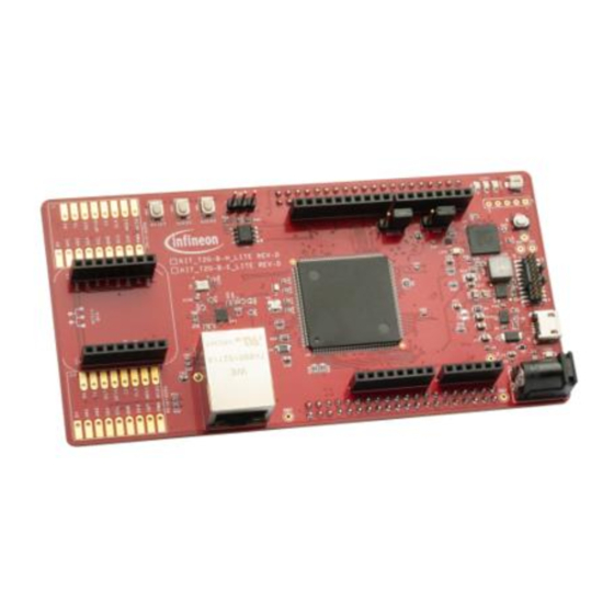
KIT_T2G-B-H_LITE board • Figure 1 Kit contents Inspect the contents of the kit; if you find any part missing, go to https://www.infineon.com/cms/en/product/microcontroller/32-bit-traveo-t2g-arm-cortex- microcontroller/traveo-t2g-cyt4bf-series. Board details The KIT_T2G-B-H_LITEhas the following features: TRAVEO™ T2G-B-H MCU – CYT4BF8CDDQ0AESGS. See the device datasheet. •... - Page 8 KIT_T2G-B-H_LITE user guide Kit details Figure 2 KIT_T2G-B-H_LITE board – top view Shield2Go connectors (Not Mounted) (J7, J19) MikroBUS connectors (J11, J12) RJ45 Ethernet connector (J6) Ethernet physical layer (PHY) transceiver (U11) 32.768-kHz oscillator for WCO (Y1) 16-MHz oscillator for ECO (Y2) 8-pin Arduino header (J13) Expansion header 1 (X1 on the bottom side) 6-pin Arduino header (J15)
- Page 9 KIT_T2G-B-H_LITE user guide Kit details Potentiometer (VR5) USER LED3 (LED5) USER LED2 (LED4) USER LED1 (LED3) Expansion Header 1 (X2 on the bottom side) 10-pin Arduino header (J16) CAN FD transceiver (U8) CAN FD connector (J5) USER2 button (SW3) USER1 button (SW2) RESET button (SW1) 25-MHz crystal for Ethernet transceiver (Y3) User Guide...
- Page 10 KIT_T2G-B-H_LITE user guide Kit details KIT_T2G-B-H_LITE board pinout details mikro BUS MISO MOSI GPIO GPIO MOSI MOSI MISO MISO Shield2Go Shield2Go (AD5/SCL) I2C_SCL UART_RX (D0) (AD4/SDA) I2C_SDA UART_TX (D1) (AREF) 5V P0_2 (D2) (GND_3) GND P0_3 (D3) (D13) SPI_CLK P2_0 (D4) (D12) SPI_MISO P2_1 (D5) (D11) SPI_MOSI...
- Page 11 KIT_T2G-B-H_LITE user guide Kit details Primary onboard function Secondary onboard Connection details function P6[5] SPIHB_SEL0 – Connected to CS of QSPI flash S25FL512SAGMFMR10 P6[0] Potentiometer (POT) output Arduino header (J15.1) – POT_AOUT P7[1] SPIHB_DATA0 – Connected to IO0 of QSPI flash S25FL512SAGMFMR10 (U9) P7[2]...
- Page 12 KIT_T2G-B-H_LITE user guide Kit details Primary onboard function Secondary onboard Connection details function MikroBUS Connector (J12.6) P14[1] UART_TX Pin D1 of connector J4.2 This pin is connected to the compatible with Arduino KitProg3 UART Rx pin. Shield2Go Connector (J7.11, Remove R132 and R142, and J19.11) install R136 to connect to Pin MIKROBUS Connector...
- Page 13 KIT_T2G-B-H_LITE user guide Kit details Primary onboard function Secondary onboard Connection details function P21[0] WCO IN (Y1) – 32.768-kHz watch crystal oscillator input P21[1] WCO OUT (Y1) – 32.768-kHz watch crystal oscillator output P21[2] ECO IN (Y2) – 16-MHz external crystal oscillator input P21[3] ECO OUT (Y2)
-
Page 14: Kit Operation
KIT_T2G-B-H_LITE user guide Kit operation Kit operation Theory of operation The TRAVEO™ T2G-B-H evaluation board is built around TRAVEO™ T2G-B-H MCU. For details of device features, see the device datasheet. ITCM DTCM CYT4BF ITCM DTCM 16 KB 16 KB 16 KB 16 KB MXS40-HT SWJ/ETM/ITM/CTI... - Page 15 KIT_T2G-B-H_LITE user guide Kit operation Infine on Parts Loade d Parts No L oad Par ts St atus L ED Mode Sw itch (16 MHz) WCO (32.768 KHz) 20 /10 Pin JTAG/ Reset Butt on SWD/ETM Header P5LP_VDD Potentiometer Arduino Headers KitProg3 KitProg3 USB (PSoC 5LP)
- Page 16 KIT_T2G-B-H_LITE user guide Kit operation User Guide 002-37237 Rev. ** 2023-07-20...
- Page 17 KIT_T2G-B-H_LITE user guide Kit operation The KIT_T2G-B-H_LITE board has the following peripherals: Table 4 Peripheral details Sl. No. Peripheral Description Shield2Go Connector Optional connector for Shield2Go Interface (DNI) MikroBUS Connector Optional connector for MikroBUS Interface (DNI) RJ45 Ethernet connector (J6) RJ45 Ethernet connector port to connect the kit to the Ethernet network.
- Page 18 KIT_T2G-B-H_LITE user guide Kit operation Sl. No. Peripheral Description CMSIS-DAP BULK mode. For more details, see the KitProg3 user guide. This button function is reserved for future use. KitProg3 status LED (LED1) Amber LED (LED1) indicates the status of KitProg3. For details on the KitProg3 status, see the KitProg3 user guide.
-
Page 19: Bsp Selection
KIT_T2G-B-H_LITE user guide Kit operation Sl. No. Peripheral Description the TRAVEO™ T2G-B-H MCU pin as a digital input with resistive pull-up for detecting the button press. T2G-B-H reset button (SW2) Resets TRAVEO™ T2G-B-H MCU. It connects the TRAVEO™ T2G-B-H MCU reset (XRES) pin to the ground. 25-MHz crystal for Ethernet Oscillator for the Ethernet PHY. - Page 20 KIT_T2G-B-H_LITE user guide Kit operation Figure 7 Connect USB cable to USB connector on the board In the Eclipse IDE for ModusToolbox™ software, import the desired code example (application) into a new workspace. Click on New Application from Quick Panel. Figure 8 Create new application User Guide...
- Page 21 KIT_T2G-B-H_LITE user guide Kit operation Select the BSP in the “Choose Board Support Package (BSP)” window and click Next. As noted in section 3.2 BSP selection, the BSP selection should be based on the combination of baseboard and radio module used. The rest of the steps assumes there is no radio module connected to the baseboard and uses the KIT_T2G-B-H_EVK BSP for the sake of explanation.
- Page 22 KIT_T2G-B-H_LITE user guide Kit operation To build and program a TRAVEO™ T2G-B-H MCU application, in the Project Explorer, select <App_Name> project. In the Quick Panel, scroll to the Launches section and click the <App_Name> Program (KitProg3_MiniProg4) configuration as shown in Figure Figure 11 Programming in ModusToolbox™...
-
Page 23: Using The Oob Example - Traveo™ T2G-B-H Mcu
KIT_T2G-B-H_LITE user guide Kit operation 3.3.1.1 Using the OOB example – TRAVEO™ T2G-B-H MCU The TRAVEO™ T2G-B-H evaluation board is by default programmed with the code example: TRAVEO™ T2G-B-H MCU: OOB demo. The following steps describe how to use the example. For a detailed description of the project refer to the example’s README.md file in the GitHub repository. -
Page 24: Usb-Uart Bridge
KIT_T2G-B-H_LITE user guide Kit operation 3.3.2 USB-UART bridge KitProg3 on the TRAVEO™ T2G-B-H evaluation board can act as a USB-UART bridge. The UART Rx and Tx pins of KitProg3 are connected to the TRAVEO™ T2G-B-H MCU UART pins as follows: KitProg3 TRAVEO T2G-B-H MCU... -
Page 25: Hardware
KIT_T2G-B-H_LITE user guide Hardware Hardware KIT_T2G-B-H_Lite Kit Connections 4.1.1 USER LEDs The correspondence between the LEDs on the board and the CYT4BF8xx device pins and the port pins are shown in Table Table 5 USER LEDs CYT4BF8xx USER LED Part Number USER LED 1 LED3 P5.0... -
Page 26: Mode Switch
KIT_T2G-B-H_LITE user guide Hardware 4.1.4 MODE switch The mode switch will change the mode of operation of the KitProg3 device. While communicating with the TRAVEO™ T2G device, make sure that the KitProg3 device should be in CMSIS DAP mode (LED1 is solid ON). - Page 27 KIT_T2G-B-H_LITE user guide General safety instructions Figure 16 Power Supply - 1 User Guide 002-37237 Rev. ** 2023-07-20...
- Page 28 KIT_T2G-B-H_LITE user guide General safety instructions Figure 17 Power Supply - 2 User Guide 002-37237 Rev. ** 2023-07-20...
- Page 29 KIT_T2G-B-H_LITE user guide General safety instructions Figure 18 KitProg3 Interface User Guide 002-37237 Rev. ** 2023-07-20...
- Page 30 KIT_T2G-B-H_LITE user guide General safety instructions Figure 19 TRAVEO T2G MCU Power User Guide 002-37237 Rev. ** 2023-07-20...
- Page 31 KIT_T2G-B-H_LITE user guide General safety instructions Figure 20 TRAVEO™ T2G-B-H-8M 176-pin MCU - 1 User Guide 002-37237 Rev. ** 2023-07-20...
- Page 32 KIT_T2G-B-H_LITE user guide General safety instructions Figure 21 TRAVEO T2G-B-H-8M 176-pin MCU - 2 User Guide 002-37237 Rev. ** 2023-07-20...
- Page 33 KIT_T2G-B-H_LITE user guide General safety instructions Figure 22 TRAVEO T2G-B-H-8M 176-pin MCU - 3 User Guide 002-37237 Rev. ** 2023-07-20...
- Page 34 KIT_T2G-B-H_LITE user guide General safety instructions Figure 23 TRAVEO T2G-B-H-8M 176-pin MCU - 4 User Guide 002-37237 Rev. ** 2023-07-20...
- Page 35 KIT_T2G-B-H_LITE user guide General safety instructions Figure 24 TRAVEO T2G-B-H-8M 176-pin MCU - 5 User Guide 002-37237 Rev. ** 2023-07-20...
- Page 36 KIT_T2G-B-H_LITE user guide General safety instructions Figure 25 TRAVEO T2G-B-E-1M 100-pin MCU User Guide 002-37237 Rev. ** 2023-07-20...
- Page 37 KIT_T2G-B-H_LITE user guide General safety instructions Figure 26 Peripheral Interface User Guide 002-37237 Rev. ** 2023-07-20...
- Page 38 KIT_T2G-B-H_LITE user guide General safety instructions Figure 27 CAN and QSPI Interface User Guide 002-37237 Rev. ** 2023-07-20...
- Page 39 KIT_T2G-B-H_LITE user guide General safety instructions Figure 28 Ethernet Transceiver User Guide 002-37237 Rev. ** 2023-07-20...
- Page 40 KIT_T2G-B-H_LITE user guide General safety instructions Figure 29 Ethernet Clock and RJ45 Connector User Guide 002-37237 Rev. ** 2023-07-20...
- Page 41 KIT_T2G-B-H_LITE user guide General safety instructions Figure 30 Ethernet Clock and RJ45 Connector User Guide 002-37237 Rev. ** 2023-07-20...
- Page 42 KIT_T2G-B-H_LITE user guide General safety instructions Figure 31 Shield2Go /MikroBUS User Guide 002-37237 Rev. ** 2023-07-20...
-
Page 43: Layouts
KIT_T2G-B-H_LITE user guide General safety instructions Layouts This section shows the board layouts of the TRAVEO T2G Body High Lite kit. User Guide 002-37237 Rev. ** 2023-07-20... - Page 44 KIT_T2G-B-H_LITE user guide General safety instructions Figure 32 Top view Figure 33 Bottom view User Guide 002-37237 Rev. ** 2023-07-20...
-
Page 45: Known Limitations
KIT_T2G-B-H_LITE user guide Known limitations This section lists the known limitations of the KIT_T2G-B-H_LITE. Table 9 Limitation information Description Workaround Application Do not use DC 12-V AC adaptor Rev. D version. Power supply from the DC power plugged to the DC Power Jack (J1). jack does not work. -
Page 46: Revision History
KIT_T2G-B-H_LITE user guide Revision history Revision history Document Date Description of changes revision 2023-07-20 Initial release User Guide 002-37237 Rev. ** 2023-07-20... - Page 47 With respect to any examples, hints or any typical WARNINGS values stated herein and/or any information 81726 Munich, Germany regarding the application of the product, Infineon Due to technical requirements products may contain Technologies hereby disclaims any and all dangerous substances. For information on the types...
Need help?
Do you have a question about the KIT T2G-B-H LITE and is the answer not in the manual?
Questions and answers