
Related Manuals for Infineon AURIX lite Kit V2


Summary of Contents for Infineon AURIX lite Kit V2
- Page 1 Eva lua t io n Bo ar d For AURIX™ Family AURIX™ lite Kit V2 Document Revision 2.0 Board Us er ‘s Ma nu al Revision 2020-10-27 M ic ro con tr o lle r...
- Page 2 Infineon Technologies components may be used in life-support devices or systems only with the express written approval of Infineon Technologies, if a failure of such components can reasonably be expected to cause the failure of that life-support device or system or to affect the safety or effectiveness of that device or system.
- Page 3 AURIX™ lite Kit V2 Revision History Page or Item Subjects (major changes since previous revision) Revision 2020, Initial relased Version is V2.0 October Trademarks of Infineon Technologies AG AURIX™, C166™, CanPAK™, CIPOS™, CIPURSE™, EconoPACK™, CoolMOS™, CoolSET™, CORECONTROL™, CROSSAVE™, DAVE™, EasyPIM™, EconoBRIDGE™, EconoDUAL™, EconoPIM™, EiceDRIVER™, eupec™, FCOS™, HITFET™, HybridPACK™, I²RF™, ISOFACE™, IsoPACK™, MIPAQ™,...
-
Page 4: Table Of Contents
Connector Pin Assignment ...................... 16 Pinout of X1 and X2 connectors ......................16 Shield2Go and MikroBus™ Pinout ..................... 17 Arduino Compatible Connector ......................18 Infineon DAP Debug Connector (10-pin) ................... 19 Schematics and Placement ...................... 20 Board Users Manual Revision October, 2020... - Page 5 AURIX™ lite Kit V2 Table of Contents List of Figures Figure 1 Block Diagram of the AURIX™ lite Kit V2 ..................... 7 Figure 2 AURIX™ lite Kit Board V2 View from the Top ..................8 Figure 3 AURIX™ lite Kit Board V2 View from the Bottom ................8 Figure 4 Power Supply Concept ........................
-
Page 6: Introduction
32-Bit Single-Chip AURIX™ TriCore™-based Microcontroller TC375, TC365, TC275 or TC265 from Infineon Technologies AG. It can be used with a range of development tools including Infineon’s free of charge Eclipse based IDE AURIX™ Development Studio or the Eclipse based “FreeEntryToolchain” from Hitecs/PLS/Infineon. -
Page 7: Block Diagram
I2C0 ADBUS2 2x LEDs QSPI0 for OCDS Single Bus ADC/AN16 EEPROM 1kB Buf f e r Gate 93LC46B-I/SN ADC/AN17 ACBUS4 20 MHz Infineon ADBUS1 GPIO External CAN Tranceiver DAP1 Connector Crystal TLE9251VSJ P21.7 EEPROM 2kB 24AA02E48-E/OT EUI-48ä Node Address Optional Semper... -
Page 8: Hardware Description
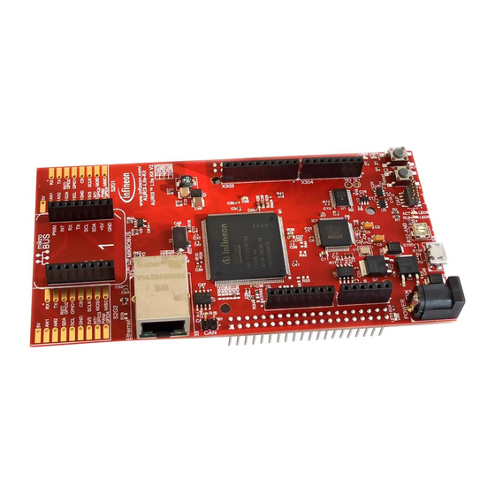
AURIX™ lite Kit V2 Hardware Description Hardware Description The following chapters give a detailed description of the board hardware and how it can be used. The different parts of the kits series are shown in Figure 2 and 3. Figure 2 AURIX™... -
Page 9: Power Supply
AURIX™ lite Kit V2 Hardware Description Power Supply The AURIX™ lite Kit V2 must be supplied by an external DC power supply, this can be done via the DC plug X3 (recommended voltage range +7 V…+14 V) or via the micro USB plug X4 (+5 V). The green Power LED4 indicates the presence of the generated 3.3 V supply voltage. -
Page 10: User Push Buttons, User Leds And Potentiometer
Pin Connector X2 +3V3 X303 X304 CAN Tranceiver Con. Potentiometer VDD_USB VEXT +3V3 Aurixä +3V3 Micro TC3X5 or TC2X5 Infineon Microcontroller IFX27001TFV33 S2G1/S2G2 On Board R39/0R_opt S2Go Slots miniWiggler U1 - U5 Infineon plug IFX27001TFV50 I2C Eeprom mikroBusä 10M / 100M... -
Page 11: Debugging And On Board Miniwiggler
AURIX™ lite Kit V2 Hardware Description Table 3 miniWiggler Pin Mapping for User LEDs Name miniWiggler Pin Color Active LED5 ADBUS4 (ACTIV) green Low-active (pull against GND) LED6 ADBUS7 (RUN) green Low-active (pull against GND) AURIX™ Push Buttons and Potentiometer Table 4 Name AURIX™... -
Page 12: Miniwiggler Jds
The AURIX™ lite Kit V2 provides a CAN interface via the CAN connector. The TLE9251V is the latest Infineon high-speed CAN transceiver generation, used inside HS CAN networks for automotive and also for industrial applications. It is designed to fulfill the requirements of ISO 11898-2 (2016) physical layer specification and respectively also the SAE standards J1939 and J2284. -
Page 13: Ethernet
AURIX™ lite Kit V2 Hardware Description Ethernet The AURIX™ lite Kit V2 provide a RJ45 connector (X5) for twisted pair ethernet connections.The board use a DP83825I Low Power 10/100 Mbps Ethernet Physical Layer Transceiver from Texas Instruments as physical interface device. For more information about the ethernet modul see AURIX™ User’s Manual, about the PHY see the DP83825I datasheet from TI website. -
Page 14: Configuration
AURIX™ lite Kit V2 Hardware Description Configuration Bootmode 1)2) Table 6 User Startup Modes HWCFG[5...3] Type of Boot Start-up mode is selected by Boot Mode Index Internal Start from Flash Alternate Boot Mode, Generic Bootstrap Loader on fail (P14.0/P14.1) Generic Bootstrap Loader (P14.0/P14.1) 1) The shadowed line indicates the default setting. -
Page 15: Optional Resistors
AURIX™ lite Kit V2 Hardware Description Optional resistors Some resistors/bridges enable/disable or changing functions of specific signals in Table 8. To disable the signals, the resistors have to be removed. To enable, the resistor has to be assembled. For example: Desoldering the intialy assembled resistor R33, disables the Potentiometer and the analog Signal AN0 of the AURIX™, making it usable for other purposes. -
Page 16: Connector Pin Assignment
AURIX™ lite Kit V2 Hardware Description Connector Pin Assignment Pinout of X1 and X2 connectors The pin headers X1 and X2 can be used to extend the evaluation board or to perform measurements on the AURIX™ TC3X5/TC2X5. Figure 5 shows the available GPIOs / signals at these pin headers. The pin table is also printed onto the bottom side of the PCB. -
Page 17: Shield2Go And Mikrobus™ Pinout
AURIX™ lite Kit V2 Hardware Description Shield2Go and MikroBus™ Pinout The pin connectors for the Shield2Go Connectors 1 and 2 and the mikroBus™ can be used to extend the evaluation board or to perform measurements on the AURIX™ TC3X5/TC2X5. Figure 6 shows the available signals at these connectors. -
Page 18: Arduino Compatible Connector
AURIX™ lite Kit V2 Hardware Description Arduino Compatible Connector The mapping of GPIOs and AURIX™ pin functions to Arduino compatible functions can be found in Figure 6. The Arduino compatible connector supports SPI interface (SPI_xxx) I2C interface (I2C_xxx) ... -
Page 19: Infineon Dap Debug Connector (10-Pin)
AURIX™ lite Kit V2 Hardware Description Infineon DAP Debug Connector (10-pin) Infineon’s 10-pin Device Access Port Debug Connector (DAP) is a two-wire tool access port for microcontrollers and similar devices. It allows robust high speed connections over a long cable for automotive applications. The... -
Page 20: Schematics And Placement
AURIX™ lite Kit V2 Hardware Description Schematics and Placement Figure 8 Schematic: Project Overview Board Users Manual Revision October, 2020... -
Page 21: Figure 9 Schematic: On Board Miniwiggler
AURIX™ lite Kit V2 Hardware Description Figure 9 Schematic: On Board miniWiggler Board Users Manual Revision October, 2020... -
Page 22: Figure 10 Schematic: Power And Connectors
AURIX™ lite Kit V2 Hardware Description Figure 10 Schematic: Power and Connectors Board Users Manual Revision October, 2020... -
Page 23: Figure 11 Schematic: Cpu And Config
AURIX™ lite Kit V2 Hardware Description Figure 11 Schematic: CPU and config Board Users Manual Revision October, 2020... -
Page 24: Figure 12 Schematic: Ethernet And Memory Expansion
AURIX™ lite Kit V2 Hardware Description Figure 12 Schematic: Ethernet and memory expansion Board Users Manual Revision October, 2020... -
Page 25: Figure 13 Placement: Top View
GPIO3 +3.3V PWM/ PWM/ MISO MISO GPIO4 GPIO4 S2G2 S2G1 Ethernet C60 C59 MIKROBUS www.infineon.com/ AURIX-Lite-Kit AURIX Lite Kit V2 TC375 TC365 TC275 TC265 R43 R42 LED3 P00.6 E SR0 POWER P00.5 Reset -AN0 Figure 13 Placement: Top View Board Users Manual... -
Page 26: Figure 14 Placement: Bottom View
AURIX™ lite Kit V2 Hardware Description mikro RST/ RST/ GPIO2 GPIO2 GPIO1 GPIO1 MISO SCLK SCLK MOSI INT/ INT/ MOSI MOSI GPIO3 GPIO3 +3.3V PWM/ PWM/ MISO MISO GPIO4 GPIO4 S2G2 S2G1 +3V3 +3V3 TXD1_ P33.12 P33.11 P33.10 S2G1 SCL0 RXD1_ P33.13 P33.7... - Page 27 . i n f i n e o n . c o m Published by Infineon Technologies AG...
Need help?
Do you have a question about the AURIX lite Kit V2 and is the answer not in the manual?
Questions and answers