
Related Manuals for M&R Renegade XL 52120


Summary of Contents for M&R Renegade XL 52120
- Page 1 $65.00 Operator’s Manual M&R PRINTING EQUIPMENT, INC. 1 N. 372 MAIN STREET - GLEN ELLYN, ILLINOIS 60137 U.S.A. www.mrprint.com 1 (800) 736-6431 Part No. MAN-RENXL 102599MS...
- Page 2 IMPORTANT! IMPORTANT! The product described in this publication may employ hazardous voltages or might cre- ate other conditions that could, through misuse, inattention, or lack of understanding, result in personal injury, or damage to the product or to other equipment. It is imperative, therefore, that personnel involved in the installation, maintenance, or use of this product understand the operation of the product and the contents of this publication.
- Page 3 The information listed below will prove helpful when ordering replacement parts, requesting service or repairs. Please fill in the following information. The Model No., Serial No., Schematic No. and Machine No. are all located on the Manufacturers Rating Plate mounted to the equipment. Should you have any questions regarding this information, please do not hesitate to contact our Equipment Service Department at 1 (800) 736-6431 during normal business hours.
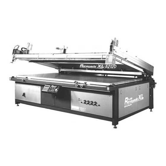
- Page 4 Introduction Valued Customer, Thank you and congratulations on your purchase of the M&R Renegade XL Graphic Screen Printing System. The M&R Renegade XL incorporates state-of-the-art microprocessor technology and an array of inno- vative features and Operator controls. An up front digital display allows the Operator to independent- ly adjust for a variety of print parameters such as print carriage speed and vacuum/blo-back pressure and timing.
- Page 5 Table of Disclaimer Contents Model Description Introduction Safety Precautions...........1 Safety Precautions & Specifications...........5 Screen Frame & Image Size......7 Specifications Installation Instructions........9 Set-Up & Control & Adjustments........13 Operation Operator Interface..........23 Sentry Take-Off..........43 Maintenance and Preventive Maintenance Procedures....45 Troubleshooting Procedure.......53 Trouble Shooting Replacement Parts...........55 Replacement Parts and Warranty Information........
- Page 6 Safety Precautions SAFETY PRECAUTIONS This equipment must be used only for the defined purpose as described in the Operator’s Manual, and must be main- FUNDAMENTAL SAFETY INSTRUCTIONS: tained in perfect running condition in accordance with Please read all information regarding safety precautions described Safety Regulations.
- Page 7 Safety Precautions This symbol signifies a possible 1. The equipment is shut down. imminent danger for life and health 2. The electrical power has been dis-connected from the persons equipment equipment. Operators. 3. In case of delivery of partial components, the Operator Non-observance these must install safety devices in accordance with regula-...
- Page 8 Safety Precautions All pneumatic piping and/or hoses must be checked at reg- 2. Safety guards have been provided to protect the opera- ular intervals for signs of wear or failure. tor from all moving parts. Please do not remove these Safety Guards any time the equipment is in operation.
- Page 9 Safety Precautions 3. PRACTICE GOOD HOUSEKEEPING: Maintain and area adjacent to NOT ON the equipment for tool and color stor- age. Clean up all spills and eliminate all potential trip points from the operating areas around the equipment to prevent slipping or falling into the working zone of the equipment.
- Page 10 Specifications SPECIFICATIONS MODEL No. RENFL-46X68 RENFL-52X84 RENFL-52X96 RENFL-52X120 Maximum Image Size 46” x 68” (116.8 x 172.cm) 52” x 84” (132 x 213.3cm) 52” x 96” (132 x 243.8cm) 52” x 120” (132 x 304cm) Maximum Frame O.D. 68” x 88” x 2.5” 74”...
- Page 11 Specifications Figure 1 Typical Compressor-Chiller Layout A clean, moisture free compressed air supply is essential for the continued oper- ation of the M&R Renegade XL press. We strongly recommend that a refrigerated air chiller be installed in the compressed air supply line to the Renegade XL press to prevent moisture damage to pneumatic seals, valves and air cylinders used in the operation of the print carriage (See diagram above).
- Page 12 Screen Frame & Image Size MODEL No. “A” “B” “C” “D” “E” RENFL - 46X68 68” (172.7cm) 88” (223.5cm) 46” (116.8cm) 68” (172.7cm) 11” (27.9cm) 74” (187.9cm) RENFL - 52X84 106” (269.2cm) 52” (132.0cm) 84” (213.3cm) 11” (27.9cm) RENFL - 52X96 74”...
- Page 13 Screen Frame & Image Size NOTES: M&R Printing Equipment, Inc. - Glen Ellyn, Illinois...
- Page 14 Installation Instructions OVERVIEW - OPERATION - Designed for screen printing medium to large range flat flex- Operation of the M&R Renegade XL is rudimentary, and ible and rigid substrates, the M&R Renegade XL Graphic there are numerous standard features for optimal produc- Screen Printing System offers the Graphic Screen Printer tion output for a wide range of applications.
- Page 15 Installation Instructions To level the press, adjust the leveling legs one at a time until the bed is level from corner to corner, then lock the nuts Fig.2 located on each leveling leg to maintain level. Now place the level on the table, running from corner to corner for the remaining two corners.
- Page 16 Installation Instructions Loosen the registration locking knobs located adjacent to Once the take-off is assembled to the press, place a car- the bed so that the support washers are slightly tightened penters level along the long dimension of the take-off on against the locking plates.
- Page 17 Installation Instructions NOTES: M&R Printing Equipment, Inc. - Glen Ellyn, Illinois...
- Page 18 Controls & Adjustments Safety Bar Set the control for a minimum of 30-40 PSI before operat- The M&R Renegade XL Flat Bed Press print head assembly ing the press. To set the air pressure, place the “On/Off” includes a yellow colored safety bar and two infrared safety control knob to “On”...
- Page 19 Controls & Adjustments Lifting or lowering of the print head assembly is accom- Off-Contact Adjustment plished by flipping up the ‘HEAD UP/HEAD DOWN” toggle An Off-Contact adjustment is switch to either “UP” or “DOWN” and then pressing the provided at each of the mas- “HEAD UP/HEAD DOWN START”...
- Page 20 Controls & Adjustments Stroke Length Sensors Squeegee and Flood bar The print stroke length may be easily adjusted by sliding the H e i g h t / P r e s s u r e stroke sensor flag along the top of the print head. Adjustments - Pressure Adjustments Precise control of ink...
- Page 21 Controls & Adjustments Air line connection/Line Lubricator Assembly Squeegee/Flood Bar Pneumatic Clamps (Optional) - The pneumatic components used in the operation of your The squeegee and flood bar are quickly installed in the print M&R Renegade XL require clean dry compressed air for carriage assembly using these two toggle switches.
- Page 22 Controls & Adjustments Vacuum slide, Lift Pins, Registration Guides, Dripless In this case both vacuum systems will be activated if select- Squeegee, Master Frame Assist and Squeegee ed for operation on the L.C.D. digital display panel. Equalizer Air Pressure Regulators - The foot switch on the right side of the foot pedal is marked Located at the lower front of the press are six air pressure “Print Start”...
- Page 23 Controls & Adjustments To resume operation of the WARNING! NEVER ATTEMPT TO BY-PASS equipment, you must press OR DEFEAT ANY SAFETY DEVICE OR the green “RESET” push APPLIANCE. IN THE EVENT THAT ANY OR button to reset the control ALL SAFETY DEVICES OR SAFETY APPLI- logic in the on-board PLC.
- Page 24 Controls & Adjustments L.C.D. Operator Interface The L.C.D. (Liquid Crystal Diode) Operator Interface control keypad is used to display alpha/numeric Power ON/OFF Toggle Switch messages regarding operational parameters such This toggle switch when placed in Take-Off ON/OFF Switch as press “Dwell Time”, production “Counters”, the “ON”...
- Page 25 Controls & Adjustments Head Lift Controls Vacuum On/Off Squeegee Flood During set-up, screen frame instal- This toggle switch activates the Speed Adjustments lation or preventive maintenance Renegades LS’s vacuum turbine. Located Operator’s procedures, the “HEAD LIFT” Due to the large surface area of the Control Panel, these controls controls allow you to manually acti- Renegade XL’s vacuum table, two...
- Page 26 Controls & Adjustments Emergency Stop This red colored mush room shaped push button will immediately stop all press operations when pressed “IN”. It is activated when fully pushed in and locked. To de-activate the Emergency Stop push button, push the red mush room shaped push button once INK DIP again to release it.
- Page 27 Controls & Adjustments NOTES: M&R Printing Equipment, Inc. - Glen Ellyn, Illinois...
- Page 28 L.C.D. Operator Interface Instructions c. Directly below the L.C.D. display window are the indi- E300 OPERATOR INTERFACE – vidual operational control buttons with L.E.D. indicators. The Operator Interface control panel used in the manufac- These control buttons are used to access the on-board ture of the M&R Renegade XL Graphic Screen Printing PLC for various printing operation, and to display system System incorporates a L.C.D.
- Page 29 L.C.D. Operator Interface Instructions TIME OUT - drive systems. Press the “ALARM LIST” key to view the The “TIME OUT” L.E.D. indicator will display a red indica- cause for the alarm condition. tion in the event that the on-board PLC detects that the dwell time interval for the print head or print carriage has TAKE-OFF NO RUN - elapsed without initiating operation of either the print head...
- Page 30 L.C.D. Operator Interface Instructions TIME OF DAY & DATE - In the lower right corner of the display you will see “HELP”. You will note that when you first power up the unit, a flash- This indication appears in the same area on all message ing frame appears around the indication for time of day in screens and is provided to quickly access information the lower middle right area of the display.
- Page 31 L.C.D. Operator Interface Instructions The “Total Counter” indicates the total press cycles from the date the system was originally put into service. This indi- cation cannot be reset and is provided merely as an indica- tion of the presses operational history. “1 Print Time”...
- Page 32 L.C.D. Operator Interface Instructions OPTIONS - As the particular vacuum section is activated, the graphic The next menu item is the “OPTIONS” menu. The representation to the right on the L.C.D. display will change “OPTIONS” menu contains 9 sub-menu items which are “ texture, confirming that this vacuum section is activated.
- Page 33 L.C.D. Operator Interface Instructions DRIPLESS SQUEEGEE CONTROL - To adjust the delay time, use the “ARROW” keys to select The next sub-menu is the “No Drip” squeegee menu. This the time indication at the right of the menu selection, now optional control feature provides a method to eliminate ink use the numerical keys to enter the desired delay time into from the squeegee dripping into the live image area during...
- Page 34 L.C.D. Operator Interface Instructions You will be prompted to enter a job reference number. REGISTRATION PINS - Press “ENTER” to save the job specifications, or “PREV” next sub-menu item under “OPTIONS” to cancel saving the job specifications. “Registration Pins”. To access the “Registration Pins” Press the “READ”...
- Page 35 L.C.D. Operator Interface Instructions To access the “Ink Dip Settings”, press the “ARROW the print carriage to move farther into the ink well area to DOWN” and “ARROW RIGHT” keys to select the “Ink Dip retrieve more of the ink supply. The “Ink Dip Time” sub- Settings”...
- Page 36 L.C.D. Operator Interface Instructions and down. This control parameter is used during set-up The next sub-menu item is “Approach Speed”. the procedures when you may wish to cycle the print carriage approach speed is the speed in which the take-off gripper up and down to evaluate flood or squeegee pressure.
- Page 37 L.C.D. Operator Interface Instructions PAPER PINS - decrease the peel rate, or the “PEEL” button to increase The last sub-menu item under “Take-Off Settings” is the peel rate. Pressing the “TESTS” button while in the sub- “Paper Pins”. This control is used to activate the vacuum menu will set the peel system for “0”...
- Page 38 L.C.D. Operator Interface Instructions The “Main Control Panel Test” displays all the electrical menu, then press the “ENTER” key. The message window switches used on the Main Control Panel, such as “Reset”, will display a list of control areas which can be monitored to Emeregency Stop Push Button”...
- Page 39 L.C.D. Operator Interface Instructions NOTES: time analysis. The MPR report filters, compiles and formats this data for output to any compatible line printer. Refer to the Management Production Report Users Manual for fur- ther information on the use of this option. HELP - The next menu item is “HELP”.
- Page 40 L.C.D. Operator Interface Block Diagram...
- Page 41 L.C.D. Operator Interface Block Diagram...
- Page 42 L.C.D. Operator Interface Block Diagram...
- Page 43 L.C.D. Operator Interface Block Diagram...
- Page 44 L.C.D. Operator Interface Block Diagram...
- Page 45 L.C.D. Operator Interface Block Diagram...
- Page 46 L.C.D. Operator Interface Block Diagram...
- Page 47 L.C.D. Operator Interface Block Diagram...
- Page 48 Sentry Take-Off Operation M&R SENTRY TAKE-OFF OPERATION The optional M&R Sentry Take-Off is the perfect compliment to the M&R Renegade XL graphics press. The M&R Sentry is designed to consistently remove and deliver to a convey- orized dryer a wide range of substrates. The use of the M&R Sentry Take-Off can make a significant contribution to your overall production rates.
- Page 49 Sentry Take-Off Operation To increase the gripper pressure, pull up on the round black knob on the regulator assembly and turn it in a counter- clockwise direction. A half to three-quarter turn is generally satisfactory to increase the gripper pressure. To decrease the gripper pressure, turn the adjustment knob in a clock- wise direction.
- Page 50 Preventive Maintenance Procedures The benefits of a regularly scheduled preventive mainte- nance program can never be over-estimated. Equipment Red adjustment screw which is properly maintained operates more efficiently, extends service life and reduces operating costs. A proper- ly managed preventive maintenance program will minimize downtime and its attendant costs before they occur, allow- ing you to be your most productive.
- Page 51 Preventive Maintenance Procedures Carriage Bearings & Raceway W3. After the initial break-in period, and only after the first W6. After the initial break-in period of one week, and only after the first week of service, check for excessive slack in week of service, check the print head lift drive chain for the optional M&R Sentry take-off gripper carriage drive tim- excessive slack.
- Page 52 Preventive Maintenance Procedures M4. Using a small brush, apply white lithium grease to the threaded rods on the micro-registration adjustment located MONTHLY: underneath the vacuum bed assembly. M1. Using a standard pump action grease gun, apply white lithium grease to the flange bearings for the peel drive and print carriage drive assemblies located under the rear top cover of the print head assembly.
- Page 53 Preventive Maintenance Procedures M7. Using a small brush, apply white lithium grease (M&R EVERY SIX MONTHS: Part No. 7018017) to the print head lift drive chains located ESM1. Remove the reservoir bowls from the air line lubri- on the left and right sides of the press chassis. (See illustra- cator and water trap assemblies and clean out any dirty oil tion below) residue which may have accumulated in the reservoir.
- Page 54 Preventive Maintenance Procedures 3. Detach front cover on Mitshubishi module A1SCPU 4. Remove the battery from the mounting clip on the cover, then disconnect the battery by gently squeezing the con- nector and gently pulling out and away from the module. Remember you have only five minutes to install the new bat- tery, otherwise the program data in the CPU may be lost.
- Page 55 PREVENTIVE MAINTENANCE LOG After completing each maintenance proce- FILL IN APPROPRIATE DATES dure, write in the pro- FOR EACH MONTH cedure number in the calendar above. MONTH/YEAR PLEASE MAKE COPIES FROM THIS ORIGINAL FOR YOUR USE SUNDAY MONDAY TUESDAY WEDNESDAY THURSDAY FRIDAY SATURDAY Daily...
- Page 56 Preventive Maintenance Procedures RECOMMENDED LUBRICANTS - Quantity & Description M&R Part No. 1 Quart No. 10 Wt. Non-Detergent Oil 7017000 1 Tube White Lithium Grease 7018017 1 Qt. Mobil Synthetic Lube 90 wt. 7017004 RECOMMENDED TOOLS - 1. Combination wrench set (Standard U.S.) 2.
- Page 57 Preventive Maintenance Procedures - RECOMMENDED SPARE PARTS - Quantity & Description M&R Part No. 1 - Push Button 1010006 1 - Emergency Stop Push Button 1010000 1 - Reset Push Button 1010001 1 - Automatic/Manual Mode Switch 1010013 1 - Toggle Switch 1010011 3 - Plastic Adjustment Knobs 3033042...
- Page 58 Troubleshooting Procedure The following information is provided as a guide for troubleshooting in the event a problem may occur during the operation of your M&R Renegade XL Graphic press. Should you have any questions regarding the installation, operation or preventive maintenance procedures for this equipment, we strongly encourage you to contact our Equipment Service Department at 1 (630) 858-6101 during normal business hours, or our 24 hour Emergency Service hotline at 1 (630) 462-4715 in the evening, week ends or holidays.
- Page 59 Troubleshooting Procedure PROBLEM PROBABLE CAUSE/SOLUTION Areas of the printed image are blurred and/or 1. The Peel Rate control is improperly adjusted. The screen frame should break away from the sub- smeared. strate immediately behind the squeegee print stroke for optimum image clarity. The servo drive peel adjustment is located on the right side of the control panel.
- Page 60 Replacement Parts OPERATORS CONTROL PANEL PART NAME PART NUMBER E300 Operator Interface Keypad 1017295 Toggle Switch (Take-Off ON/OFF) 1010011 Potentiometer 1k Ohm 2 Watts 1010006 Toggle Switch (Vacuum ON/OFF) 1010011 Push Button (Head UP/DOWN) 1010006 Push Button (Ink Dip) 1010006 1010000 Emergency Stop Push Button Power ON/OFF Toggle Switch...
- Page 61 Replacement Parts ELECTRICAL CABINET PART NAME PART NUMBER Flanged Outlet 3 Pole 4 Wire 1020037A Terminal Block 27 Pole 1003021 1009000 4” Vent Fan with Guard Mitshubishi Frequency Drive 1.5kw 1008038A Mitshubishi Frequency Drive 3.7kw 1008043A Control Transformer 1019015 1024052 24 VDC Power Supply Fuse Supply Fuse Type...
- Page 62 Replacement Parts ELECTRICAL CABINET PART NAME PART NUMBER Brake Resistor 1017072D Brake Resistor 1017072E 2 Pole Idec Relay 1011005 2 Pole Idec Relay 1011005 2 Pole Idec Relay Miniture Series 1011017 2 Pole Idec Relay Miniture Series 1011017 Mitshubishi PLC 1017040A Contactor 1011026...
- Page 63 Replacement Parts SENTRY TAKE-OFF ELECTRICAL PANEL PART NAME PART NUMBER Mac Valve Block Assembly 2012015 Idec Relay 2 Pole 120vac 1011005 Air Regulator with Gauge 1/4” 2019000 Terminal Strip 12 Pole 1003014 Fuse FLNR 10 1004037 Mitshubishi Drive 1008030A 3” Vent Fan 1009001 Brake Resistor 100 Ohm - 120 Watts 1017072A...
- Page 64 Replacement Parts PRINT CARRIAGE (No Drip Squeegee) PART NAME PART NUMBER Female Rod End 1/4” - 28 3034000 Air Cylinder 2009014 Air Cylinder Mounting Bracket (R/L) 9410440/9410441 Flow Control 2018001 Air Hose 1/4” Black 2001000 Flow Control 2018001 Plastic Adjustment Handle 3032001 Bracket (R/L) 9410415/9410414...
- Page 104 LIMITED WARRANTY M&R GRAPHIC EQUIPMENT Graphic screen printing equipment manufactured by M&R Printing Equipment, Inc. (“M&R”) is warranted against defects in workmanship and materials provided that it is properly maintained and operated under normal use for a period of one year from the date of shipment.
Need help?
Do you have a question about the Renegade XL 52120 and is the answer not in the manual?
Questions and answers