Raymarine ST40 Owner's Handbook Manual
Bidata instrument
Hide thumbs
Also See for ST40:
- User manual ,
- Service manual (70 pages) ,
- Owner's handbook manual (50 pages)

Related Manuals for Raymarine ST40


Summary of Contents for Raymarine ST40
- Page 1 Distributed by Any reference to Raytheon or RTN in this manual should be interpreted as Raymarine. The names Raytheon and RTN are owned by the Raytheon Company.
- Page 2 ST40 Bidata Instrument Owner’s Handbook Document number: 81159_2 Date: 1st May 2001...
- Page 3 Copyright © Raymarine Limited 2001...
-
Page 4: Important Information
Preface Important information WARNING Although your ST40 instrument is designed to give accurate and reliable performance, it should serve only as an aid to navigation and should never lead to the erosion of good seamanship. Always maintain a permanent watch and be aware of situations as they develop. - Page 5 ST40 Bidata Instrument Owner’s Handbook...
-
Page 6: Table Of Contents
Preface Contents Important information ... i Preface ... v Chapter 1: Operation ... 1 Chapter 2: Maintenance and Fault Finding ... 9 WARNING ... i EMC conformance ... i Handbook information ... i Parts supplied ... vi 1.1 Introduction ... 1 Display ... - Page 7 Chapter 4: Calibration ... 27 Instrument Specification ... 35 Glossary ... 37 Index ... 39 ST40 Bidata Instrument Owner’s Handbook 3.1 Planning your installation ... 15 EMC installation guidelines ... 15 Suppression Ferrites ... 16 Connections to Other Equipment ... 16 Tools required ...
-
Page 8: Preface
Preface Preface Thank you for purchasing a Raymarine product. We are sure your ST40 instrument will give you many years of trouble-free operation. This instrument is designed to provide reliable performance, even under the most demanding conditions. -
Page 9: Parts Supplied
Handbook Note: The items shown here are supplied for an ST40 Bidata system. If an instrument is purchased separately, transducers are not included. If any item is not present, contact your Raymarine Dealer. ST40 Bidata Instrument Owner’s Handbook... -
Page 10: Chapter 1: Operation
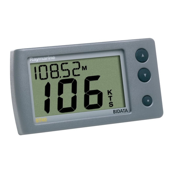
Coloured bezel and Desktop Mounting Bracket options are available for your ST40 instrument. Contact your Raymarine dealer for further information. Display The ST40 Bidata display comprises upper and lower data areas, each of which shows either depth or speed information, selected as shown in the following illustration. -
Page 11: Operating Procedures
• The average speed reading is reset to zero at power up. • The Log screen shows the total distance covered by the vessel since the ST40 Bidata instrument was fitted. • The trip reading is reset to zero at power up. - Page 12 Chapter 1: Operation Previous speed screen is displayed Current speed Maximum speed To reset 3 seconds Average speed To reset 3 seconds NORMAL OPERATION (sheet 1) Switch on DEPTH SPEED Water temp- erature Trip Note: Screens annotated with * are temporary and will time-out to the previous permanent screen after 5 seconds.
- Page 13 5 seconds. To reset This diagram shows the operating sequence for an ST40 Bidata master instrument. On a repeater instrument, only the Depth, Minimum 3 seconds depth, Speed and Water temperature screens are available.
- Page 14 Chapter 1: Operation To/from Shallow alarm screen (sheet 2) Deep alarm Shallow anchor alarm Deep anchor alarm Offset To/from Depth screen (sheet 2) NORMAL OPERATION (sheet 3) Alarm on/off 3 seconds Momentary Alarm on/off 3 seconds Momentary Alarm on/off Set Deep anchor alarm 3 seconds Momentary...
-
Page 15: Adjusting Display Backlighting And Contrast
2 seconds to move through Adjust Backlight mode and enter Adjust Contrast mode During normal operation, press to adjust contrast, press for 1 second During normal operation, press ST40 Bidata Instrument Owner’s Handbook ADJUST BACKLIGHTING for 1 second The current backlighting level is displayed. Select the required backlighting level then: ADJUST CONTRAST... -
Page 16: Alarms
Chapter 1: Operation 1.3 Alarms Alarm indications Shallow alarm Depth is equal to or less than the shallow alarm threshold. Alarm continues until cancelled manually. D4666-2 Deep alarm Triggered by depths equal to the deep alarm threshold. Continues until cancelled manually. D4789_2 Anchor alarms Depth is either:... -
Page 17: Enabling/Disabling Alarms
ST40 Bidata Instrument Owner’s Handbook Enabling/disabling alarms You can enable or disable any alarm function (i.e. switch it on or off ) by selecting the relevant alarm screen (see Normal operation) and holding down the key for 3 seconds (toggle action). -
Page 18: Chapter 2: Maintenance And Fault Finding
In order to minimise these effects and enable you to get the best possible performance from your Raymarine equipment, guidelines are given in the installation instructions, to enable you to ensure minimum interaction between different items of equipment, i.e. -
Page 19: Transducer
Periodically clean your ST40 instrument with a soft damp cloth. Do NOT use chemical or abrasive materials to clean the instrument. Transducers Refer to the Installation and Maintenance instructions supplied with the transducers. Cabling Examine all cables for chafing or other damage to the outer shield and, where necessary, replace and re-secure. - Page 20 Chapter 2: Maintenance and Fault Finding Display blank ST40 D D D D D epth reading flashes when under way No depth information Action Check fuse/circuit breaker. Check power supply. Check SeaTalk cabling and BIDATA D4738-2 connector security. ST40 BIDATA...
- Page 21 The speed transducer paddle wheel may be fouled. Clean the paddle wheel. ST40 Bidata Instrument Owner’s Handbook ST40 BIDATA ST40 BIDATA...
-
Page 22: Assistance
A group of SeaTalk instruments not working Assistance If you are unable to rectify any problem, please contact your local Raymarine Dealer for assistance. Action Check security of SeaTalk connections between instruments. Check condition of SeaTalk cables. Isolate faulty instrument by disconnecting instruments one by one. - Page 23 ST40 Bidata Instrument Owner’s Handbook...
-
Page 24: Chapter 3: Installation
Chapter 3: Installation Chapter 3: Installation This chapter describes how to install the ST40 Bidata instrument, and associated transducers. The transducers are fitted in the hull of the vessel and is connected to the rear of the instrument. 3.1 Planning your installation... -
Page 25: Suppression Ferrites
If your Raymarine equipment is going to be connected to other equipment using a cable not supplied by Raymarine, a suppression ferrite MUST always be fitted to the cable close to the Raymarine unit. Tools required The tools required for fitting the standard ST40 instrument system are shown in the following illustration. -
Page 26: Site Requirements
Chapter 3: Installation Note: If you intend fitting a nonstandard transducer, extra tools may be required Site requirements Transducers The transducer types required for the various hull types are as follows: Hull material Speed transducer M78712 Through hull plastic Steel (supplied as standard) Aluminium Wood... - Page 27 Other transducer types are available for specific requirements. For further details, contact your local Raymarine dealer. The transducers should be sited within the clear water flow areas indicated by the shaded areas below. Transducer siting Each transducer should also: • Be ahead of the propellers (by a minimum of 10% of the water line length ).
-
Page 28: Instrument
Chapter 3: Installation Depth transducer maximum angle Instrument ST40 Instrument dimensions CAUTION: The presence of moisture at the rear of the instrument could cause damage either by entering the instrument through the breathing hole or by coming into contact with the electrical connectors. -
Page 29: Procedures
Running transducer cable Each transducer type has a 9 m (30 ft) cable fitted with spade terminals for connection to the ST40 Bidata instrument. Observing the following guidelines, run the cable to the instrument: • If the cable has to be fed through the deck, always use a good quality deck gland. -
Page 30: Connections To The Instrument
Chapter 3: Installation Connections to the instrument You can connect your instrument: • Directly to the speed and depth transducers as a stand-alone master instrument. When connected in this manner, the instrument must be connected to a suitable power source using the 1 m (3 ft) power cable provided. -
Page 31: Stand-Alone Connections
Stand-alone connections CAUTION Ensure that the power supply for each stand-alone ST40 instrument is protected by a 3 A fuse or circuit breaker. Connections to a stand-alone instrument ST40 Bidata Instrument Owner’s Handbook 3 A circuit breaker Red +ve Uninsulated wire (screen) -ve... -
Page 32: Seatalk Connections
Power cable SeaTalk bus Typical SeaTalk connections Fitting the instrument Fit your ST40 instrument as shown in the following illustrations. Remove template from handbook (immediately after index), apply to required location and mark cutting centre. Note: A 5 A fuse can be used in place of 5 A circuit breaker the circuit breaker, if preferred. - Page 33 Cut hole Peel protective sheets from gasket Stick gasket to rear of instrument ST40 Bidata Instrument Owner’s Handbook 57 mm (2.25 in) cutter D4760-1 D4770-1 D4761-1...
-
Page 34: Desktop Mounting Bracket
Feed cables through clamping bracket, connect cables then secure instrument with bracket and thumb nut Desktop Mounting Bracket An optional Desktop Mounting Bracket (Part No. E25024) enables you to mount your ST40 instrument in locations where other forms of mounting are impractical. D4819-1 D4762-1... -
Page 35: Calibration Requirement
To bracket mount your ST40 instrument, do so in accordance with the Instruction Sheet, which is included with the Desktop Mounting Bracket. 3.3 Calibration requirement Once installation is complete and before you use your instrument, carry out the calibration procedures detailed in Chapter 4, Calibration. -
Page 36: Chapter 4: Calibration
Chapter 4: Calibration Chapter 4: Calibration 4.1 Introduction The procedures in this Chapter must be carried out before the equipment is used operationally, to optimise the performance of the instrument with the vessel. Calibration information is presented in flow chart form. The flow charts show the various calibration screens and key presses necessary to carry out calibration. - Page 37 • Lock the shallow alarm, to prevent unauthorised changes during normal operation. Power up the instrument then follow the procedure in the User calibration flow diagram. This diagram shows the User calibration sequence for an ST40 Bidata operating as a master instrument for both speed and depth .
- Page 38 Chapter 4: Calibration During normal operation hold down Entry screen ST40 Depth response ST40 Speed response ST40 Depth units ST40 Speed units ST40 To Distance units screen (sheet 2) USER CALIBRATION (sheet 1) for approximately 2 seconds Note: If there is no key activity when the Entry screen...
- Page 39 (decrease speed) Depth offset ST40 To save your settings and return to normal operation from any screen, hold down ST40 Bidata Instrument Owner’s Handbook USER CALIBRATION (sheet 2) BIDATA Set to BIDATA ST40 Displayed only if SOG available on SeaTalk & vessel speed greater than 0.5 kt.
-
Page 40: Depth Offsets
Chapter 4: Calibration Depth offsets WARNING: The use of incorrect offset values could result in misleading depth information being displayed with a consequent risk of running aground. The depth offset screen enables you to determine the exact point on the vessel from which depths are measured. -
Page 41: Dealer Calibration
This enables you to reapply the factory settings if you want to reset the instrument to a known operating condition. Follow the procedure in the Dealer calibration flow diagram. ST40 Bidata Instrument Owner’s Handbook INTERMEDIATE CALIBRATION During normal operation hold down... - Page 42 Chapter 4: Calibration hold down Calibration access Boat show mode ST40 BIDATA CAUTION: Do NOT switch the Boat Show mode on. This function must only be used for demonstration purposes. To save your settings and return to normal operation from any screen,...
- Page 43 ST40 Bidata Instrument Owner’s Handbook...
-
Page 44: Instrument Specification
Instrument Specification Instrument Specification Supply voltage: Current consumption (12 V supply): Operating temperature: Interfaces: Overall dimensions: Boss diameter: Speed range: Log range: Trip reading range: Temperature reading range: Depth range: Shallow depth alarm: Deep depth alarm: Shallow anchor alarm: Deep anchor alarm: Approvals: CE - conforms to 10 V to 16 V dc. - Page 45 ST40 Bidata Instrument Owner’s Handbook...
-
Page 46: Glossary
Glossary Glossary Cal factor Calibration factor. Used in the ST40 Speed and Bidata instruments to ensure the current speed reading is the actual speed. Values are from 0.25 (reduce speed reading) to 2.5 (increase speed reading). Electromagnetic Compatibility. Fathoms. Feet. - Page 47 ST40 Bidata Instrument Owner’s Handbook...
-
Page 48: Index
Index Index Alarms 7–8 enable/disable 8 indications 7 ranges 35 setting thresholds 4–5 silencing 2 switching on and off 4–5 Average speed reset 2, 3 Backlighting 6 Boat show mode 32 Calibration 27–33 Dealer 32–33 Intermediate 31–32 setting appropriate response val- ues 27 setting user access 33 User 27–31... - Page 49 30–31 depth response 29 depth units 29 shallow alarm lock 29 speed response 29 speed units 29 Shallow alarm lock 29 ST40 Bidata Instrument Owner’s Handbook Site requirements 17–20 instrument 19 transducers 17–20 Software version 31 Specifications 35 Speed...
-
Page 52: Limited Warranty Certificate
During this period, except for certain products, travel costs (auto mileage and tolls) up to 100 round trip highway miles (160 kilometres) and travel time of 2 hours, will be assumed by Raymarine only on products where proof of installation or commission by authorized service agents, can be shown. -
Page 53: Factory Service Centers
Factory Service Centers United States of America Raymarine Inc 22 Cotton Road, Unit D Nashua, NH 03063-4219, USA Telephone: +1 603 881 5200 Fax: +1 603 864 4756 www.raymarine.com Sales & Order Services Telephone: +1 800 539 5539 Ext. 2333 or +1 603 881 5200 Ext.
Need help?
Do you have a question about the ST40 and is the answer not in the manual?
Questions and answers