
Related Manuals for LG FH2


Summary of Contents for LG FH2
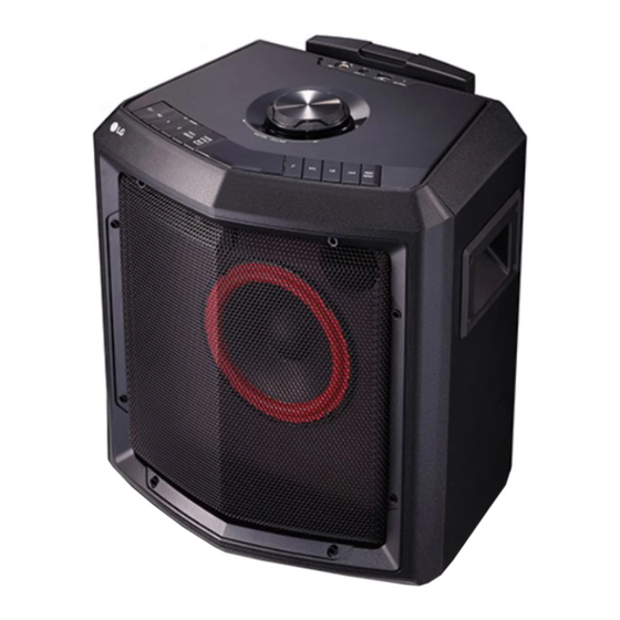
- Page 1 Internal Use Only HIGH POWER SPEAKER SYSTEM SERVICE MANUAL MODEL: FH2 CAUTION BEFORE SERVICING THE UNIT, READ THE “SAFETY PRECAUTIONS” IN THIS MANUAL. P/NO : AFN77912803 MARCH, 2017...
- Page 2 CONTENTS SECTION 1 ..SUMMARY SECTION 2 ..CABINET & MAIN CHASSIS SECTION 3 ..ELECTRICAL...
-
Page 3: Table Of Contents
SECTION 1 SUMMARY CONTENTS PRODUCT SAFETY SERVICING GUIDELINES FOR AUDIO PRODUCTS ............ 1-3 SERVICING PRECAUTIONS ..........................1-4 • GENERAL SERVICING PRECAUTIONS • INSULATION CHECKING PRODEDURE • ELECTROSTATICALLY SENSITIVE (ES) DEVICES HIDDEN KEY MODE ............................1-5 PROGRAM DOWNLOAD & UPDATE GUIDE ....................1-6 SPECIFICATIONS ............................. -
Page 4: Product Safety Servicing Guidelines For Audio Products
When servicing this product, under no circumstances should the original design be modified or altered without permission from LG Corporation. All components should be replaced only with types identical to those in the original circuit and their physical location, wiring and lead dress must conform to original layout upon completion of repairs. -
Page 5: Servicing Precautions
SERVICING PRECAUTIONS CAUTION: Before servicing the Audio products covered by this Electrostatically Sensitive (ES) Devices service data and its supplements and addends, read and fol- Some semiconductor (solid state) devices can be damaged low the SAFETY PRECAUTIONS. easily by static electricity. Such components commonly are NOTE: if unforeseen circumstances create conflict between called Electrostatically Sensitive (ES) Devices. -
Page 6: Hidden Key Mode
DISPLAY RESULT STATUS KEY(Audio) POWER ON Custom code : SW version 2s Factroy Reset STATUS 2C2C+0xF0(LG MP2) Auto power off --> option 2s Initialize MIC not connected b + B.Skip for 3s --> E2P CLEAR POWER ON MIC + Function... -
Page 7: Program Download & Update Guide
PROGRAM DOWNLOAD & UPDATE GUIDE Caution: • When downloading the fi le, you should neither unplug the USB device, change to the other function, nor power off the device. • USB device must be unplugged when the downloading process is completed. If security program (Water Wall) is activated on your PC, you must save the fi... -
Page 8: Specifications
SPECIFICATIONS GENERAL Power requirements Refer to the main label on the unit. Power consumption Refer to the main label on the unit. Dimensions (W x H x D) Approx. 352.5 mm x 419.6 mm x 269.2 mm Net Weight Approx. - Page 10 SECTION 2 CABINET & MAIN CHASSIS CONTENTS HOW TO DISASSEMBLE THE BATTERY ....................... 2-2 DISASSEMBLY & ASSEMBLY INSTRUCTIONS ..................... 2-3 1. DISASSEMBLY GUIDE ..........................2-3 2. ASSEMBLY STRUCTURE AND METHOD ....................2-4 EXPLODED VIEWS ............................2-7 1. CABINET AND MAIN FRAME SECTION ....................2-7 2.
-
Page 11: How To Disassemble The Battery
HOW TO DISASSEMBLE THE BATTERY Battery 1) Remove the screws. 2) Remove the bottom cover. 3) Disconnect the battery cable. 4) Remove the battery. -
Page 12: Disassembly & Assembly Instructions
DISASSEMBLY & ASSEMBLY INSTRUCTIONS 1. DISASSEMBLY GUIDE ※ Please be careful so as not to cause scratches during disassembly. 1) Front panel assembly (Screw PA3) 2) Top panel assembly 3) SMPS PCB assembly (Screw PA3) 4) Battery assembly (Screw BM4) -
Page 13: Assembly Structure And Method
2. ASSEMBLY STRUCTURE AND METHOD Note: Disassembly is reverse of the assembly method. 1) Tweeter Woofer assembly (Screw PA3.5) 2) Side Handle assembly (Screw KA3.5) 3) Top panel assembly 4) Battery assembly (Screw BM4) 5) Front panel assembly (Screw PA3) 6) SMPS PCB assembly (Screw PA3) - Page 14 ASSEMBLY STRUCTURE AND METHOD 7) Handle assembly (Screw BM4) 8) Foot/ Wheel rubber assembly (Screw PWM4/ Screw PA3) 9) Final products Figure) Top panel assembly (Screw PA3)
-
Page 16: Exploded Views
EXPLODED VIEWS 1. CABINET AND MAIN FRAME SECTION CABLE6 CABLE7 CABLE9 SMPS CABLE8 CABLE10 CABLE4 CABLE11 CABLE12 FRONT MAIN CABLE2... -
Page 17: Packing Accessory Section
2. PACKING ACCESSORY SECTION Owner’s manual Power cord 803T Packing 803B Packing 802 Box 2-10... - Page 18 SECTION 3 ELECTRICAL CONTENTS ONE POINT REPAIR GUIDE ..........................3-2 1. NO POWER PROBLEM ......................... 3-2 2. SPEAKER NO SOUND ........................... 3-6 3. PORTABLE FUNCTION DOESN’T WORK .................... 3-7 4. BT FUNCTION DOESN’T WORK ......................3-8 ELECTRICAL TROUBLESHOOTING GUIDE ....................3-9 1.
-
Page 19: One Point Repair Guide
ONE POINT REPAIR GUIDE 1. NO POWER PROBLEM No power problem occurs when you power on the unit. 1-1. CON4 22 VA 1-1-1. Solution Replace F1, IC8 on SMPS board. 1-1-2. How to troubleshoot (Countermeasure) Case 1) AC/DC OUT has no voltage (Battery’s voltage): Check F1, R6, R8 and replace it. Case 2) CON4 22 VA Abnormal: Check IC8, Q6, D10 and replace it. -
Page 20: Power Problem
ONE POINT REPAIR GUIDE NO POWER PROBLEM No power problem occurs when you power on the unit. 1-2. No Charge 1-2-1. Solution Replace F2, R6, R8 on SMPS board. 1-2-2. How to troubleshoot (Countermeasure) Case 1) VD (11 V-15.3 V) Abnormal: Check AC TO DC circuit. Case 2) CN1 (10.5 V-14.8 V) Abnormal: Check F2, R6, R8 and replace it. - Page 21 ONE POINT REPAIR GUIDE NO POWER PROBLEM No power problem occurs when you power on in AC power cord off status. (No Display) 1-3. Battery 1-3-1. Solution Replace Battery on set bottom place. 1-3-2. How to troubleshoot (Countermeasure) 1) AC power plug off. 2) Please check AC/DC JACK4 pin5 voltage.
- Page 22 ONE POINT REPAIR GUIDE NO POWER PROBLEM No power problem occurs when you power on. (No Display) 1-4. DSP (Micom) IC105 1-4-1. Solution Replace IC105, IC9, Y2 on MAIN board. 1-4-2. How to troubleshoot (Countermeasure) 1) Please check Vcc voltage. (pin A4, A10, D4, D14, P4, P14, U5, U6, U9 of IC105 3.3 V) If 3.3 V voltage doesn’t come out, replace IC9.
-
Page 23: Speaker No Sound
ONE POINT REPAIR GUIDE 2. SPEAKER NO SOUND No Sound when you TURN ON the unit. 2-1. Digital AMP (IC13) 2-1-1. Solution Replace IC13 on MAIN board. 2-1-2. How to troubleshoot (Countermeasure) 1) Please check 3.3 V of IC13 pin13. If 3.3 V voltage doesn’t come out, replace IC9. -
Page 24: Portable Function Doesn't Work
ONE POINT REPAIR GUIDE 3. PORTABLE FUNCTION DOESN’T WORK 3-1. ADC (IC3) 3-1-1. Solution Replace IC3, JACK10 on MAIN board. 3-1-2. How to troubleshoot (Countermeasure) 1) Please check 5.0 V of IC3 pin3. If 5.0 V voltage doesn’t come out, replace IC11. 2) Please check 3.3 V of IC3 pin4. -
Page 25: Bt Function Doesn't Work
ONE POINT REPAIR GUIDE 4. BT FUNCTION DOESN’T WORK 4-1. BT Module 4-1-1. Solution Replace IC105, PN102 on MAIN board. 4-1-2. How to troubleshoot (Countermeasure) 1) Please voltage check 3.3 V of PN102 pin12. If 3.3 V voltage doesn’t come out, replace IC9. 2) Please check IC105 pin L1, L2, K1, K2, M2, P7, N7 signal and replace it. -
Page 26: Electrical Troubleshooting Guide
ELECTRICAL TROUBLESHOOTING GUIDE 1. SYSTEM POWER SUPPLY ON SMPS BOARD No 22 VA Is the PWR-CTRL(3.3 V) Check PWR-CTRL of SMPS Board. supplied to D12? Is the AD/DC OUT(10.5 V-14.8 V) Check F1, R6, R8 and replace it. supplied to C45? Check Q6 and replace it. - Page 27 ELECTRICAL TROUBLESHOOTING GUIDE SYSTEM POWER SUPPLY ON SMPS BOARD No Charge Is VD(11 V-15.3 V) normal? Is CN1(10.5 V-14.8 V) Check F1, R6, R8 and replace it. normal? Check IC3 and replace it. Is IC3 normal? Check IC5 and replace it. Is IC5 normal? Is IC4 normal? Check IC4 and replace it.
- Page 28 ELECTRICAL TROUBLESHOOTING GUIDE SYSTEM POWER SUPPLY ON SMPS BOARD AC TO DC abnormal? Replace F2. Is F2 normal? Replace BD1. Is BD1 normal? Replace Q3. Is Q3 normal? Is IC2 normal? Replace IC2. Replace D3. Is D3 normal? Power line of MAIN PCB is short. 3-11...
-
Page 29: Power
ELECTRICAL TROUBLESHOOTING GUIDE 2. NO POWER Turn ON/OFF Switch on (ON). Check SMPS board. 1. Check connection Status on SMPS board CON1 and MAIN board JACK4. Check voltage 11~15 V 2. Check connection Status on SMPS board CON4 in JACK4 pin5(AC/DC). and MAIN board JACK8. -
Page 30: Button Operation
ELECTRICAL TROUBLESHOOTING GUIDE 3. NO BUTTON OPERATION No Button operation If no voltage change, check button and resister. JACK2 4pin Voltage spec: SW5: 0 V, SW4: 0.356 V, SW3: 0.837 V, Press button, SW1: 1.324 V, SW11: 2.363 V. check JACK2 pin3, 4. JACK2 3pin Voltage spec: SW10: 0 V, SW9: 0.356 V, SW8: 0.837 V, SW7: 1.323 V, SW6: 1.979 V. -
Page 31: Bt Operation
ELECTRICAL TROUBLESHOOTING GUIDE 4. NO BT OPERATION No BT operation Pair BT connection? Change BT function and try to pair. Check L330. Check PN102 pin10(3.3 V). Check L34. Check L34(3.3 V). Check IC9 or IC11. Check IC9 pin7(5 V). Firmware update and BT module chage. 3-14... - Page 32 ELECTRICAL TROUBLESHOOTING GUIDE 5. NO AUDIO OUTPUT FM function Check IC7 2pin(3.3 V), Check IC6, Q7, L325, IC6 & Q7. JACK4 pin4, 6(3.3 V). 1. Check L13, L22. 2. Check connection status JACK8. Check IC13 pin2, 3, 34, 35(22 V). 3.
-
Page 33: Audio Output
ELECTRICAL TROUBLESHOOTING GUIDE NO AUDIO OUTPUT PORT.IN function Check IC2 pin4, 8(3.3 V). Check L313, IC105. Check signal Check L30, L31, L32. IC2 pin2, 10. Check L319, IC105. Check L319(3.3 V). USB function Check IC10. Check IC10 pin6(5 V). Check soldering status Check R1. - Page 34 ELECTRICAL TROUBLESHOOTING GUIDE NO AUDIO OUTPUT MIC function Check IC105 pin78(3.3 V) Check R15, R42, L326, JACK301. after inserting MIC. Check IC4. Check MIC signal L35. Check L38, L40, IC5. Check IC5 pin3(5 V), pin4(3.3 V). 3-17...
-
Page 35: Waveforms Of Major Check Point
WAVEFORMS OF MAJOR CHECK POINT 1. SYSTEM PART-1 (X-TAL) FIG 1-1. DSP (IC105) 3-18... -
Page 36: System Part-2 (I2S Signal)
2. SYSTEM PART-2 (I2S SIGNAL) FIG 2-1. AMP (IC13) FIG 2-2. AMP (IC13) FIG 2-3. AMP (IC13) FIG 2-4. AMP (IC13) 3-19... -
Page 37: System Part-3 (I2C Signal)
3. SYSTEM PART-3 (I2C SIGNAL) FIG 3-1. AMP (IC13) FIG 3-2. AMP (IC13) 3-20... -
Page 38: System Part-4 (Pwm Signal)
4. SYSTEM PART-4 (PWM SIGNAL) FIG 4-1. AMP (IC13) 3-21... -
Page 39: System Part-5 (Battery Input - Ac Off Status)
5. SYSTEM PART-5 (BATTERY INPUT - AC OFF STATUS) FIG 5-1. BATTERY INPUT 3-22... -
Page 40: Wiring Diagram
WIRING DIAGRAM JACK9 3P/2.0 AUX IN MIC IN JACK15 3P/2.0 FM PCB JACK3 CON8 6P/2.0 PN102 6P/2.0 10P/1.0 FFC 10P/1.0 BT MOUDLE JACK5 MAIN PCB SW SPK OUT JACK14 JACK2 JACK8 3P/2.0 JACK4 6P/2.0 2P/3.96 8P/2.0 Switch Tone JACK15 6P/2.0 FRONT PCB CON1 CON4... -
Page 41: Block Diagrams
BLOCK DIAGRAMS 1. SYSTEM BLOCK DIAGRAM RADIO DISPLAY IC105 IC12 PORT. IN AMP. AMP. MIC-IN IC13 DC TO DC DC TO DC SUPPLY +3.3V / +1.2V IC11 3-25 3-26... -
Page 42: Power Block Diagram
2. POWER BLOCK DIAGRAM 8P/2.0MM AC DET. CTRL-ERP-TEST PWR_CTRL H=SMPS STOP WORK 14.6V 0.41A AC/DC BATT GREEN H=WORK AC TO DC Battery Charger MAIN BOOST +22V 14.6V 6A Controller 22V 3A 2P/3.96MM 2P/3.96MM 3-27 3-28... -
Page 43: Circuit Voltage Chart
CIRCUIT VOLTAGE CHART 1. ICs 2. CONNECTORS LOCATION NAME PIN NUMBER PIN FUNCTION SPEC. (V) CONNECTOR NO. PIN FUNCTION SPEC. (V) MAIN Board 3.3 V ± 0.3 V FLASH IC 3.3 V ± 0.3 V 3.3 V ± 0.3 V Analog Switch IC 5 V ±... -
Page 44: Printed Circuit Board Diagrams
PRINTED CIRCUIT BOARD DIAGRAMS 1. SMPS P. C. BOARD DIAGRAM NOTE) Warning Parts that are critical with respect to risk (TOP VIEW) of fire or electrical shock. (BOTTOM VIEW) 3-31 3-32... - Page 45 2. MAIN P. C. BOARD DIAGRAM (TOP VIEW) 3-33 3-34...
-
Page 46: Main P. C. Board Diagram
MAIN P. C. BOARD DIAGRAM (BOTTOM VIEW) 3-35 3-36... -
Page 47: Front P. C. Board Diagram
3. FRONT P. C. BOARD DIAGRAM (TOP VIEW) (BOTTOM VIEW) 3-37 3-38... -
Page 48: Fm P. C. Board Diagram
4. FM P. C. BOARD DIAGRAM (TOP VIEW) (BOTTOM VIEW) 5. VOLUME CONTROL P. C. BOARD DIAGRAM (TOP VIEW) (BOTTOM VIEW) 3-39 3-40... -
Page 49: Mic P. C. Board Diagram
6. MIC P. C. BOARD DIAGRAM (TOP VIEW) (BOTTOM VIEW) 3-41 3-42...
Need help?
Do you have a question about the FH2 and is the answer not in the manual?
Questions and answers