
Related Manuals for FAAC 455D220A.5


Summary of Contents for FAAC 455D220A.5
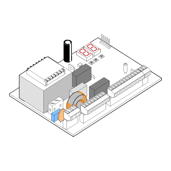
- Page 1 455 D 455 D Control Board FAAC International Inc. FAAC International Inc. West Coast Operations Headquarter & East Coast Operations 357 South Acacia Avenue 3160 Murrell Rd Fullerton, CA 92831 Rockledge, FL 32955 Tel. 800 221 8278 www.faacusa.com...
- Page 2 Semi-automatic B / Dead-man C Opening/Closing Time: Connector J2 - Rapid Connection to RP Receivers Programmable (from 0 to 120 s) The 5 pin J2 connector allows to plug in the FAAC RP radio Pause Time: receivers Programmable (from 0 to 4 min.) Closing Leaf Delay: Programmable (from 0 to 4 min.)
- Page 3 5. Electric Connections VAC MAX. 24 V DC 230 VAC LIMIT-SWITCHES 115 VAC 60 Hz For connection OPEN A of the safety 12 V AC devices, see the OPEN B Maglock next paragraph STOP Note: Capacitors are supplied with the operator or the prewired enclosure OP FSW - Opening safety devices contact (N.C.): Terminal Block J4 - Motors and Warning Lamp The opening safety input is used to protect the leaf move-...
- Page 4 To comply with the UL325 standard for gate operators every entrapment zone, as defined in ASTMF2200, must be pro- ADVANCED PROGRAMMING tected by two independent entrapment protection devices. One of the devices is inherent in the FAAC operators or the Display Function Default control board design, the other can be external, like a pho- tocell or an edge sensor.
- Page 5 Only one monitored photocell can be connected to the See the following connections diagrams for example of Closing or Opening safety inputs. More than one photocell opening/closing safety wiring. or other device can be connected to the safety inputs, but they will not be monitored.
- Page 6 7. Operating Logics The following table displays the sequence of functions This is a brief description of the main operating logics of the accessible in BASIC PROGRAMMING: system. For a complete description please refer to Table 3 • E (semi-automatic): This mode requires a command to BASIC PROGRAMMING press open and a command to close.
- Page 7 Display Function Default Advanced Programming: INDICATOR-LIGHT: To access ADVANCED PROGRAMMING, press and hold key F and then press key +: : the output functions as a standard indicator- light (ON at opening and pause, flashing at • Release key +, the unit displays the name of the first closing, and OFF when gate is closed).
- Page 8 9. Start-up Rotation direction and force check: 1. Program the functions of the 455 D control board ac- LED Indicators: cording to need, as previously shown. The board has a two-digit display. When not in 2. Turn power off to the control board. “PROGRAMMING”...
- Page 9 11. Final Tests 10. Learning Operating Times Once programming is complete and the proper operating WARNING: During the learning procedure, safety times are stored in the board’s memory perform a devices are disabled! Avoid crossing the leaf complete test the system. Verify that the operator(s) run properly and, most importantly, check that force is movement area when this operation is carried out.
- Page 10 12. Operating Modes Detailed Description (1) If maintained, it prolongs the pause until disabled by the command (timer function) (2) If a new pulse occurs within 2 seconds after reversing, it immediately stops operation. (3) During the partial opening cycle, an OPEN A pulse causes total opening. NB.: Effects on other active pulse inputs in brackets.
- Page 11 (1) If maintained, it prolongs the pause until disabled by the command (timer function) (2) If a new pulse occurs within 2 seconds after reversing, it immediately stops operation. (3) During the partial opening cycle, an OPEN A pulse causes total opening. NB.: Effects on other active pulse inputs in brackets.
- Page 12 13. Prewired Enclosure The 455D board can be easily installed in a prewired enclosure supplied by FAAC that integrates a number of functions: Power ON-OFF switch and accessory power outlet, loop detector sockets prewired to the board, large terminal strips to easily connect activations, accessories and safeties.
- Page 13 230 V AC Power Wiring Guidelines 115 V Check local wiring codes in all cases and follow all local building codes. Wiring and hookup should be performed by qualified electricians/installers only. AC power should be supplied from a circuit breaker panel and must have its own dedicated circuit breaker.
- Page 14 Maglock. The Maglock kit can be ordered separately as an accessory. Refer to this schematic for the connections. If using non-FAAC relay make sure the minimum switch volt- age is less than 12Vac 24 VDC...
- Page 15 LIMITED WARRANTY FAAC International, Inc. (“Seller”) warrants the first Purchaser All products sold by the Seller are subject to design and/or of the product to be free from defects in material and work- appearance modifications, which are production standards manship for a specific period as defined by the Warranty at the time of shipment.
- Page 16 455D - 532218 - Rev.B - US © 2021, FAAC International, Inc. - All Rights Reserved Published in Jan. 2021...
Need help?
Do you have a question about the 455D220A.5 and is the answer not in the manual?
Questions and answers