FAAC 412 Installation Manual
Hide thumbs
Also See for 412:
- Manual (57 pages) ,
- Installation instructions manual (23 pages) ,
- Installation manual (20 pages)
Table of Contents
Advertisement
T
4 1 2 O
H E
4 5 5 D C
I
The 412 Operator General Characteristics
Install the 455 D Control Panel
Exploded View, 412
412 Parts List
The 455 D Control Panel General Description
Connect the Main Power Supply
Connect the Operator to the Control Panel
Check the Motor's Direction of Rotation
Connect Other Devices
Set Other Operating Controls
Programming
Learning of Operating Times
Learning of Normal Times
Learning Times with Gatecoder
Automated Systems Test
Logic Tables of 455 D Control Panel
Maintenance
Safety in Gate Design
Troubleshooting
Limited Warranty
P E R A T O R A N D
O N T R O L
CONTENTS
P
A N E L
M
A N U A L
2
4
5
6
6
6
7
7
10
12
13
14
14
14
15
15
16
18
20
22
22
22
23
24
26
26
27
28
J a n u a r y , 2 0 0 4
:
FAAC International, Inc.
303 Lexington Avenue
Cheyenne, WY 82007
www.faacusa.com
Advertisement
Table of Contents

Related Manuals for FAAC 412


Summary of Contents for FAAC 412
-
Page 1: Table Of Contents
N S T A L L A T I O N A N U A L CONTENTS Important Safety Information Technical Data Unpacking the Operator The 412 Operator General Characteristics Installation Instructions Prepare the Gate Manual Release Mechanism Install the Operator Install the 455 D Control Panel... -
Page 2: J A N U A R Y , 2 0 0 4
J a n u a r y , 2 0 0 4 4 1 2 O p e r a t o r A n d P a g e 2 4 5 5 D C o n t r o l P a n e l I n s t a l l a t i o n M a n u a l MPORTANT AFETY NFORMATION... - Page 3 • Do not touch the equipment with damp or periodically check and maintain the equipment. humid hands or feet. U.L. C FAAC O LASS AND PERATOR Model Duty Cycle Typical Use Class I: Residential Vehicular Gate Operator •...
-
Page 4: Technical Data
14.3 (6.5) Current draw, A Maximum amperage draw 800 mA 800 mA for accessories, mA 1) While the 412 Operator is capable of 18 or 30 cycles/hr, as a residential-duty operator it is not designed for such continuous, sustained operation. -
Page 5: Unpacking The Operator
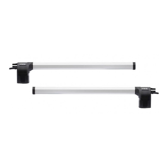
(1) Control panel enclosure with control panel and photobeams inside (only 1 per kit). (2) 412 Operator units. One is marked SX and one is marked DX. Be sure to install each on the proper Motor Power cable gate leaf (see Figure 2). -
Page 6: Installation Instructions
∗ The site is subject to strong or very gusty wind. The torque of the 412 Operator is set during Basic Programming of the 455 D Control Panel. (see page 20 For gates with two leaves, two operators are installed. -
Page 7: Manual Release Mechanism
The Manual Release mechanism is a built-in release model must be installed. device of the 412 Operator (see Figure 4). To access the keyhole, remove the plug on the top of the motor Installing the operator on the wrong side makes it housing. - Page 8 11 13/16 in. (30 cm) Outward swinging gate: 4 in. If you are installing the 412 Operator to swing the gate (10 cm) outward, construct a steel elbow of sufficient size to attach to the gate pillar and rear mounting bracket (see Figure 7 for elbow dimensions).
- Page 9 Gate post Axis of rotation (or column) for gate leaf Centerline of gate leaf Figure 7. Important mounting dimensions for outward-swinging 412 operators, top view Steel elbow Mounting Dimensions 90-deg Swing 110-deg Swing 5 3/4 in. (14.5 cm) 4 7/8 in. (12.5 cm) 5 3/4 in.
- Page 10 Locate the control panel enclosure in the most convenient position possible, considering the movement of the gate. Figure 12 shows a basic layout for a two- leaf gate with the 412 Compact Operator. Installing the control panel consists of the following general steps: •...
- Page 11 J a n u a r y , 2 0 0 4 4 1 2 O p e r a t o r A n d P a g e 1 1 4 5 5 D C o n t r o l P a n e l I n s t a l l a t i o n M a n u a l Figure 12.
- Page 12 P a g e 1 2 4 5 5 D C o n t r o l P a n e l I n s t a l l a t i o n M a n u a l The 412 Compact Operator...
- Page 13 Strain Relief, 412 390009 Skin Pack, 412 (1 pack = 2 operators) *Models Manufactured before 2000 used a screw in type cylinder assembly. The part number for this type cylinder is 736039. The manufacture date is the NR number on...
- Page 14 ESCRIPTION gate system meets all applicable electrical codes. The installer should refer to the installation manual The FAAC 455 D control panel is used to operate the for a given operator for more information. following models. : An installation is U.L. compliant only...
- Page 15 J a n u a r y , 2 0 0 4 4 1 2 O p e r a t o r A n d P a g e 1 5 4 5 5 D C o n t r o l P a n e l I n s t a l l a t i o n M a n u a l ONNECT THE PERATOR TO THE...
- Page 16 The gate leaf (or leaves) should open. If a gate leaf closes, then you need to turn off the : UL does not recognize the FAAC system main power and reverse the connection of the red with loop detectors or safety edges. FAAC...
- Page 17 (N.O.) contacts. Connect such U.L. Listed gate devices to terminals 9 and 14. operator(s) : The FAAC radio receiver plugs into the 5 prongs labeled J2 (Quick connect port). Page 19 shows how to connect a three or four wire OP_A Command Given No Command receiver.
- Page 18 Turn the main power off before you The warning light is on steadily during OGIC make any electrical connections. opening and flashes during closing. For all FAAC hydraulic operators using the 455 D THER PERATING ONTROLS control panel, the force must be set at its maximum setting of 50 in order to supply the correct voltage to the operator.
- Page 19 4 5 5 D C o n t r o l P a n e l I n s t a l l a t i o n M a n u a l Magnetic Lock Free Exit Loop/ Phone/ Firebox (Hold Open Dev ices) Lock 12 vac Relay N.C. N.O. Shadow Loop FAAC Rev ersing Photocells (f or opening) Additional Reversing Devices Coil Voltage = Additional Motor Voltage Reversing Devices N.C.
- Page 20 J a n u a r y , 2 0 0 4 4 1 2 O p e r a t o r A n d P a g e 2 0 4 5 5 D C o n t r o l P a n e l I n s t a l l a t i o n M a n u a l ROGRAMMING BASIC PROGRAMMING program...
- Page 21 J a n u a r y , 2 0 0 4 4 1 2 O p e r a t o r A n d P a g e 2 1 4 5 5 D C o n t r o l P a n e l I n s t a l l a t i o n M a n u a l ADVANCED PROGRAMMING NDICATOR ICHT...
- Page 22 J a n u a r y , 2 0 0 4 4 1 2 O p e r a t o r A n d P a g e 2 2 4 5 5 D C o n t r o l P a n e l I n s t a l l a t i o n M a n u a l •...
- Page 23 J a n u a r y , 2 0 0 4 4 1 2 O p e r a t o r A n d P a g e 2 3 4 5 5 D C o n t r o l P a n e l I n s t a l l a t i o n M a n u a l The procedure has ended and the gate is ready to •...
- Page 24 J a n u a r y , 2 0 0 4 4 1 2 O p e r a t o r A n d P a g e 2 4 4 5 5 D C o n t r o l P a n e l I n s t a l l a t i o n M a n u a l A (Automatic) Logic (455 D) Gate Status Open A...
- Page 25 J a n u a r y , 2 0 0 4 4 1 2 O p e r a t o r A n d P a g e 2 5 4 5 5 D C o n t r o l P a n e l I n s t a l l a t i o n M a n u a l E (Semi-automatic) Logic (455 D) Gate Status Open A...
- Page 26 4 5 5 D C o n t r o l P a n e l I n s t a l l a t i o n M a n u a l AINTENANCE 412 O 455 D C PERATOR ONTROL ANEL Keep the Control Panel free from spider webs, insects, The FAAC 412 Operator requires no maintenance. etc. Otherwise Control Panel requires Periodically inspect the operator, however, to ensure maintenance.
- Page 27 50 in programming for hydraulic operations. speed of your model of operator. For example, because the 412 CBAC has a rated opening time of 13 sec, you Verify that the LEDs FSWOP, FSWCL, and the STOP are should set the time at 20 or 25 seconds.
- Page 28 Neither FAAC S.p.A. related systems and equipment manufactured by FAAC or FAAC International, Inc., shall be liable for any loss or S.p.A. and distributed by FAAC International, Inc., to be damage whatsoever resulting, directly or indirectly, free from defects in material and workmanship under from the use or loss of use of the product(s).
Need help?
Do you have a question about the 412 and is the answer not in the manual?
Questions and answers