
Related Manuals for NSR Marine NVR-9000

Summary of Contents for NSR Marine NVR-9000
- Page 1 USER MANUAL Voyage Data Recorder (VDR) / NVR-9000 & Simplified Voyage Data Recorder (SVDR) / NVR-9000S NVR-9000 & NVR-9000S UM.E 20220727-14...
- Page 2 Safety Warning DON’T DISASSEMBLED THE EQUIPMENT Access to the interior of the NVR-9000 should only be by an NSR certified technician. PROPER USE OF BATTERIES The battery should be replaced when the marked expiry date is reached, even it has never been used.
- Page 3 Junction Box and 2016/07/24 Product improvement Remote Alarm Unit 2016/10/24 Product improvement 2016/12/08 Alarm message 2017/03/06 General modification 2018/06/19 Cover modification 2018/12/27 General modification 2020/02/20 General modification 2021/07/30 General modification 2021/09/28 BAM description 2022/07/27 IMO new regulations NVR-9000 & NVR-9000S UM.E 20220727-14...
-
Page 4: Table Of Contents
2.3.4 System Setting ........................ 16 2.3.5 Diagnostics ........................17 2.3.6 Service ..........................18 2.4 System Performance Test ......................20 3. DATA RECORDING UNITS ......................21 3.1 Backup of Recorded Data ......................21 3.2 Long-term Recording Unit (LRU) .................... 22 NVR-9000 & NVR-9000S UM.E 20220727-14... - Page 5 7. SPECIFICATIONS ..........................40 7.1 Specifications ..........................40 7.2 Power Supply ..........................41 7.3 Equipment List .......................... 41 ANNEX A ALERT LIST ........................42 ANNEX B ICONS ..........................46 ANNEX C NEB-2000C-VDR USER MANUAL ................47 NVR-9000 & NVR-9000S UM.E 20220727-14...
-
Page 6: Overview
The data recorded by VDR can be used for vessel management, such as equipment health management, ship position management. NVR-9000 is flexible to form a VDR or SVDR, and easy to install and maintain. The equipment is designed to meet the latest standards including:... -
Page 7: System Configuration
NVR-9000 & NVR-9000S USER MANUAL 1.2 System Configuration NVR-9000/NVR-9000S comprises up to 9 components as below: NVR-9000 NVR-9000S Environmental Component Name Part No. SVDR Category Data Acquisition Unit (DAU) NVR9001 Protected Data Extension Unit (DEU) NVR9002 Protected Remote Alarm U nit (RAU) -
Page 10: System Description
1.3 System Description The VDR system continuously stores data in FPC and FFC for at least 48 hours by overwriting the old data with new data. Following data may be recorded by NVR-9000: - Date and time - Ship’s Position... -
Page 11: Data Acquisition Unit (Dau)
Data Extension Unit (DEU) has 64 volt-free dry contact inputs, 8 wet contact inputs, 8 analog inputs for ± 10V or 4-20mA signal, and 16 serial inputs. NOTE: Up to 4 DEUs may be connected to DAU of NVR-9000 VDR. NVR-9000 & NVR-9000S UM.E 20220727-14... -
Page 12: Remote Alarm Unit (Rau)
NVR-9000 & NVR-9000S USER MANUAL 1.3.3 Remote Alarm Unit (RAU) Remote Alarm Unit (RAU) is used to check and display alarms generated in DAU. 1.3.4 Indoor Microphone Unit (IMU) and Outdoor Microphone Unit (OMU) The VDR system comes with two types of the microphones, indoor microphones and outdoor microphones. -
Page 13: Fixed Protective Capsule (Fpc)
NVR-9000 & NVR-9000S USER MANUAL 1.3.5 Fixed Protective Capsule (FPC) Fixed Protective Capsule (FPC) with memory capacity of 64GB supports data recording time of at least 48 hours. The capsule is built to withstand extreme environmental conditions such as 1100° C temperature, penetration, 6000m underwater pressure and immersion while maintaining the data integrity. - Page 14 NVR-9000 & NVR-9000S USER MANUAL VIU NVR9004-1 can connect one channel of video, while VIU NVR9004-2 can connect two channels of videos. Four channels can be configured up to 4 IP address: 172.16.8.90, 172.16.8.91, 172.16.8.92, 172.16.8.93, Port 5000. If only two channels, IP respectively 172.16.8.90 and 172.16.8.91.
-
Page 15: Operation
NVR-9000 & NVR-9000S USER MANUAL 2. OPERATION 2.1 Power On/Off In accordance to IMO regulations, the VDR shall be kept operational at all times and be powered off only for maintenance purposes. Power On: Use the key to open the door of the Data Acquisition Unit. The AC power switch and battery power switch are located on the right top corner. -
Page 16: Operation Of Rau
NVR-9000 & NVR-9000S USER MANUAL 2.2 Operation of RAU The Remote Alarm Unit (RAU) can by operated by key & knob on panel or touch-screen. ove the knob to sele When operating with knob, m ct an item on screen and press the knob to confirm the selection. -
Page 17: Screen Components
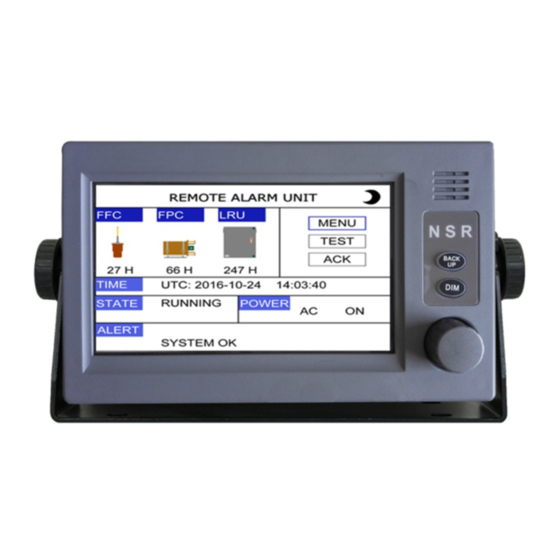
NVR-9000 & NVR-9000S USER MANUAL 2.2.1 Screen Components Actual Recording Hours / requirement Time Mode Power Status Alert message Item Symbol Meaning UTC time Time Mode Local time RUNNING Normal status State Status BACKUPING Back up status Stop Stop status... -
Page 18: Normal Operation
NVR-9000 & NVR-9000S USER MANUAL ② Press the DIM button to adjust the brightness. NOTE: When the power is turned off, the last status of brightness is stored. Therefore, when the power is turned on again, the screen will display with the last brightness before powered off. -
Page 19: Data Backup
NVR-9000 & NVR-9000S USER MANUAL VIU: Status of Video Acquisition Unit MIC: Status of Microphone channels DAU: Status of Data Acquisition Unit DEU1: Status of Data Extension Unit 1 Status Indication: - : Related recording function of the channel is not in use. -
Page 20: Alert List
NVR-9000 & NVR-9000S USER MANUAL 2.3.3 Alert List VDR generates an alert at the “Alert column” of main screen when it detects a situation that requires attention. All possible alerts are listed in Annex A. There are two ways to enter the Alert list. -
Page 21: System Setting
NVR-9000 & NVR-9000S USER MANUAL Select a alert and click [VIEW] to check more information Click [LOG] to check alert history 2.3.4 System Setting NVR-9000 & NVR-9000S UM.E 20220727-14... -
Page 22: Diagnostics
NVR-9000 & NVR-9000S USER MANUAL 2.3.4.1 KEY BUZZER Click the [KEY BUZZER] to switch the key buzzer on or off. 2.3.4.2 KNOB BUZZER Click the [KNOB BUZZER] to switch the knob buzzer on or off. 2.3.4.3 LANGUAGE The default menu language is English. -
Page 23: Service
NVR-9000 & NVR-9000S USER MANUAL 2.3.5.2 LCD TEST Press DIM to test the Display Brightness. 2.3.5.3 KEY TEST When any key is clicked, the box corresponding to the key will be filled with blue color. Press [EXIT] 3 times consecutively to return to a higher menu. - Page 24 NVR-9000 & NVR-9000S USER MANUAL 2.3.6.2 COM MONITOR It’s to check the communication sentences on the I/O ports. 2.3.6.3 Factory Set It’s to restore the system setting as factory settings. NOTE: Please remember all settings will be cleared if this function is executed.
-
Page 25: System Performance Test
NVR-9000 & NVR-9000S USER MANUAL 2.3.6.4 Reboot Click “REBOOT” to reboot the remote alarm unit. 2.4 System Performance Test Click the “TEST” to initiate the system performance test. The system performance test checks the power supplies, microphones, image and data recording functions. It will generate a test report where be restored data from the FPC/FFC/LRU and save to the USB memory in DAU. -
Page 26: Data Recording Units
NVR-9000 & NVR-9000S USER MANUAL 3. DATA RECORDING UNITS Portable USB disk in the NVR-9000 is mandatory peripheral for proper operation of the VDR system. Removal, stealing, unauthorized possession or illegal usage of the disk drive is strictly forbidden. 3.1 Backup of Recorded Data When required to back up the last recorded data, the data can be manually saved to the USB flash stick. -
Page 27: Long-Term Recording Unit (Lru)
LRU in NVR9001 DAU. For NVR-9000 VDR, LRU has memory size of 512GB. Prior to abandon ship, the recorded data can be manually saved to the USB flash stick or just take away the LRU (SSD) instead. The LRU (SSD) can be physically removed from the Data Acquisition Unit by following the below procedure. - Page 28 NVR-9000 & NVR-9000S USER MANUAL Step 1: Find the drawbar in the photo below. Step2: Pull out the drawbar to release the two belts. Step 3: Lift the FPC by two handles. NVR-9000 & NVR-9000S UM.E 20220727-14...
-
Page 29: Data Playback
Copy the software to the computer which the playback shall operate on. Double click on the “NVR-9000 Playback Software” icon to start the application. If the recorded data has been copied to the computer, the data can be played back directly. If the data is not downloaded, connect the playback computer to the VDR with the LAN cable to the “DATA”... - Page 30 NVR-9000 & NVR-9000S USER MANUAL Playback page will appear in the next window: Open and Download menu are located on the top right corner of the page. Download: Download data to the desired directory. Open: Open the data in the selected directory.
-
Page 31: Download The Data
NVR-9000 & NVR-9000S USER MANUAL 4.3 Download the Data Click on the DOWNLOAD menu and the following page is displayed. NVR-9000 & NVR-9000S UM.E 20220727-14... -
Page 32: Open The Data File
NVR-9000 & NVR-9000S USER MANUAL Set Start date and time of data to be downloaded. Set End date and time of data to be downloaded. Select Data source from: - Float-Free Capsule (FFC); - Fixed Protective Capsule (FPC); or - Long-term Data Recording Unit (LRU). -
Page 33: Playback Operation Menu
NVR-9000 & NVR-9000S USER MANUAL When the data had been download or saved in the destination file, playback procedure as follows: Click on OPEN menu; Choose the File to be playback. (File name format: YYYYMMDD), click on OK; Click on to playback the data;... -
Page 34: Main Interface
NVR-9000 & NVR-9000S USER MANUAL 4.5.1 Main Interface Main Interface page displays the following standard information: Wind Depth Heading Speed Rudder Steering Order and response Engine Order and response Thruster ... -
Page 35: Digital Data
NVR-9000 & NVR-9000S USER MANUAL VDR Player Serial Data DAU COM1~COM8 S1~S8 DEU1 COM1~COM16 S9~S24 DEU2 COM1~COM16 S25~S40 DEU3 COM1~COM16 S41~S56 DEU4 COM1~COM16 S57~S72 4.5.3 Digital Data Digital Data records the change of the state, and the meaning of the status with 0 and 1 to indicate. - Page 36 NVR-9000 & NVR-9000S USER MANUAL contacts), at this moment the LED on the board next to the switch interface is bright. Switch "0" represents the open circuit state (dry contact) and low level (wet contact), at this time the LED on the board next to the switch interface board is off.
-
Page 37: Analog Data
NVR-9000 & NVR-9000S USER MANUAL 4.5.4 Analog Data Analog Data displays status of the analog signals. Analog Data includes Point Value, Property (Voltage and current), Value and Unit. The amount of species simulated by the jumper cap to select input, can choose Current or Voltage. - Page 38 NVR-9000 & NVR-9000S USER MANUAL Below the Analog table, there are Channel, Description, Property and so on. Channel:Corresponding to the A001-A008 DEU expansion box. (Note: Because of the analog interface in the expansion enclosure is only 8, so please don't add more than 8 devices.) ...
- Page 39 NVR-9000 & NVR-9000S USER MANUAL NOTE:Two sets of data must be filled to be able to correct the real analog conversion, otherwise the actual values displayed by default to 0. As shown below, two group A001 respectively (-10, -35), (10, 35).
-
Page 40: Radar/Ecdis Image
NVR-9000 & NVR-9000S USER MANUAL 4.5.5 Radar/ECDIS Image Radar/ECDIS is connected through VGA/NET. VGA Image VGA page displays the recorded image captured by VGA (VIU) during the period of playback. VGA image from 4 different equipments can be selected for playback. Only 1 VGA image is displayed at a time. -
Page 41: Interface
Accelerations and hull stresses √ Wind speed and direction √ Any other equipment providing data in IEC61162 Format Serial Data received by NVR-9000/NVR-9000S is in NMEA format as defined in the IEC61162 and IEC61996 standards. NVR-9000 & NVR-9000S UM.E 20220727-14... - Page 42 NVR-9000 & NVR-9000S USER MANUAL Parameter to be Recorded Sentence Format Date and time Ship’s position and datum used GNS, DTM, GLL, GGA, RMC, NSR Speed (water and/ or ground) VBW, VLW, VTG Heading (true) THS, HDT Heading (magnetic) Depth (echo sounder)
-
Page 43: Maintenance
NVR-9000 & NVR-9000S USER MANUAL 6. MAINTENANCE 6.1 Fuse Replacement After opening the DAU door, you will see the fuses behind the door. 3A for Battery and 5A for the AC power. If the fuse blown, choose the right fuse to replace. Remove the shelter on the PCB boards, find the Main Power or the BATT. - Page 44 NVR-9000 & NVR-9000S USER MANUAL When VDR was tested and type approved, all parts were integral part of the VDR equipment. If a counterfeit part is used, this VDR equipment will automatically lose the guarantee of all type approval certificates unless all tests needed for type approvals have been done again for the unit installed with counterfeit part.
-
Page 45: Specifications
NVR-9000 & NVR-9000S USER MANUAL 7. SPECIFICATIONS 7.1 Specifications Item Specification Ethernet IEC61162-450 4 ch Serial IEC61162-1/2 8 ch VHF Audio 2 ch Interface Microphone 8 ch Remote Alarm Unit 1 ch 1 ch Data Acquisition Unit (DAU) Remote Alarm Unit (RAU) 1 ch Fixed Protective Capsule (FPC)... -
Page 46: Power Supply
NVR-9000 & NVR-9000S USER MANUAL 7.2 Power Supply Item Specification Data Acquisition Unit (DAU) AC100V/220V, 0.5~1.5A, 50/60Hz Data Extension Unit (DEU) DC24V, 0.5A Video Interface Unit (VIU) DC24V, 0.3A 7.3 Equipment List NVR-9000S SVDR Part No Description NVR-9000 VDR NVR9001 Data Acquisition Unit (DAU)... -
Page 47: Annex A Alert List
NVR-9000 & NVR-9000S USER MANUAL ANNEX A ALERT LIST Alert Alert Title Alert Description Prio Reason Identifier 3009 RAU LOST Check RAU DAU lost connect with RAU 3009 DAU LOST Check DAU RAU lost connect with DAU 3023 AC POWER LOST... - Page 48 NVR-9000 & NVR-9000S USER MANUAL Alert Alert Title Alert Description Prio Reason Identifier 3003 DEU3 COM Check DEU3 COM DEU3 Com Port Connection Fail 3003 DEU4 COM Check DEU4 COM DEU4 Com Port Connection Fail 3003 MIC FAIL Check MIC...
- Page 49 NVR-9000 & NVR-9000S USER MANUAL Alert Alert Title Alert Description Prio Reason Identifier 3003 DEU1 COM14 LOST Check device on DEU1 COM14 Device on DEU1 COM14 LOST 3003 DEU1 COM15 LOST Check device on DEU1 COM15 Device on DEU1 COM15 LOST...
- Page 50 NVR-9000 & NVR-9000S USER MANUAL Alert Alert Title Alert Description Prio Reason Identifier 3003 DEU4 COM6 LOST Check device on DEU4 COM6 Device on DEU4 COM6 LOST 3003 DEU4 COM7 LOST Check device on DEU4 COM7 Device on DEU4 COM7 LOST...
-
Page 51: Annex B Icons
NVR-9000 & NVR-9000S USER MANUAL ANNEX B ICONS Icon Meaning Alert: “Active” Caution. FFC is configured. FPC is configured. LRU is configured. Display mode: DAY. NVR-9000 & NVR-9000S UM.E 20220727-14... -
Page 52: Annex C Neb-2000C-Vdr User Manual
NVR-9000 & NVR-9000S USER MANUAL ANNEX C NEB-2000C-VDR USER MANUAL NVR-9000 & NVR-9000S UM.E 20220727-14... - Page 53 USER MANUAL 406 MHz EPIRB & VDR Float-free Capsule (FFC) (COSPAS-SARSAT) NEB-2000C-VDR NEB-2000C-VDR UM.E 20220727-08...
- Page 54 SAFETY NOTICES Use this EPIRB/FFC only during situations of GRAVE and IMMINENT danger. Read this manual carefully before installation and use. To prevent FALSE ALERT, it is recommended that the user should be aware of and understand basic use of this EPIRB/FFC.
- Page 55 MODIFY RECORD No. Modify by Date Paragraph Version Reason 2015/11/19 First edition 2015/12/22 Photos replaced 2017/03/06 Product improvement 2018/06/19 Cover modification 2018/12/27 General modification 2020/02/20 General modification 2022/04/15 General modification 2022/07/27 1, 2, 3, 4, 5 Add RLS function etc. NEB-2000C-VDR UM.E 20220727-08...
- Page 56 TABLE OF CONTENTS 1. DESCRIPTION ............................. 1 1.1 Product Overview ........................1 1.2 Cospas-Sarsat System Overview ....................1 1.3 Features And Components ......................4 1.4 Specifications ..........................7 2. INSTALLATION..........................8 2.1 Mounting ............................. 8 2.2 Placing ............................8 2.3 VDR Connection ......................... 9 3.
-
Page 57: Description
NEB-2000C-VDR USER MANUAL 1. DESCRIPTION 1.1 Product Overview NEB-2000C-VDR (406MHz Satellite EPIRB & VDR Float-free Capsule) is used to transmit distress signals. This is designed to comply with IMO SOLAS requirements (GMDSS) and Cospas-Sarsat technical standard (T.001). This is a powerful self-contained distress transmitter. NEB-2000C-VDR with a built-in GNSS receiver transmits distress signal including a position with accuracy of less than 10 meters. - Page 58 NEB-2000C-VDR USER MANUAL ground receiving stations, referred to as Local Users Terminals (LUTs), which receive and process the satellite downlink signal to generate distress alerts; and Mission Control Centers (MCCs) which receive alerts produced by LUTs and forward them to Rescue Coordination Centers (RCCs), Search and Rescue Points Of Contacts (SPOCs) or other MCCs.
- Page 59 NEB-2000C-VDR USER MANUAL acquired by the beacon through an internal or an external navigation receiver and encoded in the beacon message, or derived, with possible delays, from the LEOSAR System. MEOSAR Cospas-Sarsat is in the process of upgrading its satellite system by placing search-and-rescue receivers (i.e., repeaters or transponders) on new GPS satellites operated by the United States, navigation satellites of Russia (GLONASS) that began deployment last year, and European GALILEO navigation satellites that began launching 12 October 2012.
-
Page 60: Features And Components
NEB-2000C-VDR USER MANUAL 1.3 Features and Components FEATURES 64GB memory capacity to record at least 48 hours onboard data Built in GNSS receiver. 406MHz transmission together with 121MHz.homing & AIS transmitter. Highly efficient battery. Professional design, engineered, tested and built for years of abusive marine use. ... - Page 61 NEB-2000C-VDR USER MANUAL VDR Outdoor cable Antenna VDR Data cable Hydrostatic Release Unit (HRU) Ejector Switch Data Cable Cutter Strobe LEDs Night-vision Infrared LEDs Deactivation Magnet Lanyard for Hand-free Carry Water Sensor Buoyant Lanyard Battery Pack Antenna: The antenna is a flexible stick that is used to transmit signal. When operating, it must be stick-up vertically.
- Page 62 NEB-2000C-VDR USER MANUAL Buoyant Lanyard: The 7-meter durable lanyard is used to tie the EPIRB/FFC when in raft or in sea. It can be used as a tether (to a life raft, lifeboat or person in the water but not to the ship). Lanyard for hand-free carry: This lanyard is used as hand-free carriage.
-
Page 63: Specifications
NEB-2000C-VDR USER MANUAL 1.4 Specifications Model NEB-2000C-VDR Material ABS Plastic EPIRB/FFC Color High visibility orange IP Grade IP67 Buoyant General Automatic hydrostatic release Deployment Manual switch control Hydrostatic Release Unit Accessories Buoyant lanyard Lanyard for hand-free carry Controls Manual activation / Self-Test switches EPIRB 1.5 kg Weight... -
Page 64: Installation
NEB-2000C-VDR USER MANUAL 2. INSTALLATION Before installing the EPIRB/FFC, find a suitable mounting position on the vessel. It should be mounted upright against a vertical bulkhead. It is critical that you choose a position where the released EPIRB/FFC will not get trapped by overhangs, even in case that the vessel sinks. Mount the EPIRB/FFC by the below rules: Consider easy access in an emergency. -
Page 65: Vdr Connection
NEB-2000C-VDR USER MANUAL Step 2. Bend the antenna along the pole of NHR-100. Step 3. Sit the EPIRB/FFC into the container. “THIS SIDE UP” should be upside. Step 4. Step 5. Press down the upper cover. Step 6. Fix the lock pin into the hole of NHR-100 pole. CAUTION: When the EPIRB/FFC is placed into the container, make sure right direction. -
Page 66: Operation
NEB-2000C-VDR USER MANUAL 3. OPERATION 3.1 Activation The EPIRB/FFC can be activated in two ways: automatic activation and manual activation. When activated, the EPIRB/FFC will behave in below steps. Step 1. All LED flickers once one by one. Step 2. Strobe light flickers every 3 seconds. - Page 67 NEB-2000C-VDR USER MANUAL Summary of LED status in Activation EPIRB/FFC State Strobe Light LOW BATT GNSS STATUS Normal TX: Flash Flash every 3 seconds GNSS receiving Flash Flash every 3 seconds GNSS fixed Flash every 3 seconds GNSS standby Flash every 3 seconds Position valid Flash every 3 seconds Position invalid...
- Page 68 NEB-2000C-VDR USER MANUAL When the vessel sinks, the container is filled with seawater. The NHR-100 will operate when the container sinks under about 4 meters depth from the surface of water. The plastic pole of NHR-100 is pulled out while the internal coil spring is pressed by water pressure. The cable cutter is activated to cut the data cable.
- Page 69 NEB-2000C-VDR USER MANUAL Switch Cover Protector Open the switch cover. The protector tab will be broken. Slide the switch fully to left side at ON position. The EPIRB/FFC is activated and transmits distress signals. Hold or put the EPIRB/FFC on the surface as upright as possible, and it must have a clear view of the sky for proper operation.
-
Page 70: Test Mode
NEB-2000C-VDR USER MANUAL 3.2 Test Mode Take the EPIRB/FFC out of the container. Through the hole on the switch cover, use a screw driver or a pen to press the TEST button for 3 seconds and release the button. The test operation begins and will last for about 30 seconds. STATUS LED indicates the result of self-test. -
Page 71: Maintainance
NEB-2000C-VDR USER MANUAL 4. MAINTAINANCE 4.1 Regular Check As an important part of GMDSS, EPIRB should be checked regularly. has a built-in NEB-2000C-VDR test capability which can check the situation of the battery, strobe light, and both 406MHz and AIS/121.5MHz distress transmitters. Checklists are provided at the back of this book, and you should check the EPIRB/FFC regularly using the forms. - Page 72 NEB-2000C-VDR USER MANUAL Step 4. If the RLS protocol is programmed, RLS LED flashes every second, otherwise RLS LED keeps OFF. Step 5. Sending a 121.5 MHz test homing signal to check the power and Frequency. TX LED flashes short once. Step 6.
-
Page 73: Replace Hru And Cable Cutter
NEB-2000C-VDR USER MANUAL NOTE: 1. GNSS receiver inside of the EPIRB/FFC is powered off when doing Self-Test. So GNSS LED status does not mean GNSS position locked or not at Self-Test. 2. During the test, do not break the protection tab and do not open the switch cover. 3. -
Page 74: Replace Battery Pack
NEB-2000C-VDR USER MANUAL Please contact NSR authorized agent to carry out the replacement. For example, the above sticker shows the expiry date of April 2024. 4.4 Replace Battery Pack The expiry date is marked on the EPIRB/FFC, and it should be checked regularly. The battery pack NBT400 should be replaced when one of below cases happens: The EPIRB/FFC has been used in an emergency situation. -
Page 75: Vdr Module
NEB-2000C-VDR USER MANUAL 4.5 VDR Module In accordance with SOLAS Chapter V Regulation 18.8, the VDR shall be subject to an annual performance check. A ship is required under International rules to carry a functioning VDR. The person carrying out the annual checks should be approved by the ship’s Flag Administration and has been authorized by NSR. -
Page 76: Return Link Service (Rls)
NEB-2000C-VDR USER MANUAL 4.7 Return Link Service (RLS) RLS SYSTEM The EPIRB/FFC, when activated, transmits the RLS status together with the distress signal on 406MHz. When the earth station receives this message, an acknowledgment can be returned to the EPIRB/FFC through the Galileo system (only operational system for time being). -
Page 77: Warranty
NEB-2000C-VDR USER MANUAL 5. WARRANTY All goods manufactured by NSR are warranted to be free from defect in workmanship and material for the period of 18 months from the date of delivery (unless stated otherwise and confirmed in writings), or 12 months from the date of installation, whichever comes first. PROVIDED: (a) NSR is given full particulars in writing of any claim prior to the expiration of such a period and within fourteen days of the discovery of the alleged defect. - Page 78 NEB-2000C-VDR USER MANUAL PRE-DELIVERY INSPECTION LOG Battery pack: Batch date: ......................Replacement date: .................... Hydrostatic Release Unit and Cable Cutter: Batch date: ......................Replacement date: .................... Housing inspection:.................... Watertight verification: .................. 121.5MHz transmission: .................. 406MHz transmission: .....................
- Page 79 NEB-2000C-VDR USER MANUAL PERIODIC INSPECTION LOG Battery pack: Batch date: ......................Replacement date: .................... Hydrostatic Release Unit and Cable Cutter: Batch date: …...................... Replacement date: .................... Housing inspection: .................... Watertight verification: .................. 121.5MHz transmission: .....................
- Page 80 NEB-2000C-VDR USER MANUAL PERIODIC INSPECTION LOG Battery pack: Batch date: ......................Replacement date: .................... Hydrostatic Release Unit and Cable Cutter: Batch date: …...................... Replacement date: .................... Housing inspection: .................... Watertight verification: .................. 121.5MHz transmission: .....................
- Page 81 NEB-2000C-VDR USER MANUAL PERIODIC INSPECTION LOG Battery pack: Batch date: ......................Replacement date: .................... Hydrostatic Release Unit and Cable Cutter: Batch date: …..................... Replacement date: .................... Housing inspection: ................... Watertight verification: .................. 121.5MHz transmission: ................... ...
- Page 82 NEB-2000C-VDR USER MANUAL PERIODIC INSPECTION LOG Battery pack: Batch date: ......................Replacement date: .................... Hydrostatic Release Unit and Cable Cutter: Batch date: …..................... Replacement date: .................... Housing inspection: ................... Watertight verification: .................. 121.5MHz transmission: .....................
- Page 83 NEB-2000C-VDR USER MANUAL EPIRB/FFC LOCATION LOG Vessel Name: ...................... ID No.: ........................ Port of Registry: ....................----------------------------------------------------------------------------------------------------- Installation Date: .................... Registration Date: ....................Inspection Stamp: Date, Signature: NEB-2000C-VDR UM.E 20220727-08...
- Page 84 NEB-2000C-VDR USER MANUAL EPIRB/FFC LOCATION LOG Vessel Name: ...................... ID No.: ........................ Port of Registry: ....................----------------------------------------------------------------------------------------------------- Installation Date: .................... Registration Date: ....................Inspection Stamp: Date, Signature: NEB-2000C-VDR UM.E 20220727-08...
- Page 85 NEB-2000C-VDR USER MANUAL EPIRB/FFC LOCATION LOG Vessel Name: ...................... ID No.: ........................ Port of Registry: ....................----------------------------------------------------------------------------------------------------- Installation Date: .................... Registration Date: ....................Inspection Stamp: Date, Signature: NEB-2000C-VDR UM.E 20220727-08...
- Page 86 Copyright by NEW SUNRISE CO., LTD. (NSR) www.nsrmarine.com info@nsrmarine.com July, 2022...
Need help?
Do you have a question about the NVR-9000 and is the answer not in the manual?
Questions and answers