
Related Manuals for NSR Marine NVR-9000

Summary of Contents for NSR Marine NVR-9000
- Page 1 USER MANUAL Voyage Data Recorder (VDR) / NVR-9000 Simplified Voyage Data Recorder (SVDR) / NVR-9000S NVR-9000 & NVR-9000S UM.E 20200220-11...
- Page 3 Safety Warning DON’T DISASSEMBLED THE EQUIPMENT Access to the interior of the NVR-9000 should only be by an NSR certified technician. PROPER USE OF BATTERIES The battery should be replaced when the marked expiry date is reached, even it has never been used.
- Page 4 General modification 2016/01/28 Modify Alarm Message 2016/05/03 Software upgrade Junction Box and 2016/07/24 Product improvement Remote Alarm Unit 2016/10/24 Product improvement 2016/12/08 Alarm Message 2017/03/06 General modification 2018/06/19 Cover modification 2018/12/27 General modification 2020/02/20 General modification NVR-9000 & NVR-9000S UM.E 20200220-11...
-
Page 5: Table Of Contents
4.5 Playback Operation Menu ....................32 4.5.1 Main Interface ......................33 4.5.2 Serial Data ........................33 4.5.3 Digital Data ........................34 4.5.4 Analog Data ......................... 36 4.5.5 Radar Image/ECDIS ....................39 4.5.6 Door Status ........................39 NVR-9000 & NVR-9000S UM.E 20200220-11... - Page 6 4.1 SELF TEST & INSPECTION ....................16 4.1.1 SELF TEST ........................17 4.1.2 IMPORTANT NOTICE ....................19 4.2 REPLACE HRU AND CABLE CUTTER ................20 4.3 Replace battery pack ......................... 21 4.4 VDR MODULE ........................21 NVR-9000 & NVR-9000S UM.E 20200220-11...
-
Page 7: Overview
The data recorded by VDR can be used for vessel management, such as equipment health management, ship position management. NVR-9000 is the first generation of NSR VDR product, flexible to form a VDR or SVDR, easy to install and maintain. The product is designed to meet the following standards:... -
Page 8: System Configuration
NVR-9000 & NVR-9000S USER MANUAL 1.2 System Configuration NVR-9000/NVR-9000S comprises up to 9 components as below: NVR-9000 NVR-9000S Environmental Component Name Part No. SVDR category Data Acquisition Unit (DAU) NVR9001 Protected Data Extension Unit (DEU) NVR9002 Protected Remote Alarm U nit (RAU) - Page 9 NVR-9000 & NVR-9000S USER MANUAL NVR-9000 VDR SYSTEM CONFIGURATION NVR-9000 & NVR-9000S UM.E 20200220-11...
- Page 10 NVR-9000 & NVR-9000S USER MANUAL NVR-9000S SVDR SYSTEM CONFIGURATION (standard) NVR-9000 & NVR-9000S UM.E 20200220-11...
-
Page 11: System Description
NVR-9000 & NVR-9000S USER MANUAL 1.3 System Description The VDR system continuously store data in FPC and FFC for at least 48 hours by overwriting the old data with new data. Following data may be recorded by NVR-9000: Date and time Ship’s Position Speed... -
Page 12: Data Acquisition Unit (Dau)
Data Extension Unit (DEU) has 64 volt-free dry contact inputs, 8 wet contact inputs, 8 analog inputs for ±10V or 4-20mA signal, and 16 serial inputs. Note: Up to 4 DEUs may be connected to DAU of NVR-9000 VDR. NVR-9000 & NVR-9000S UM.E 20200220-11... -
Page 13: Remote Alarm Unit (Rau)
NVR-9000 & NVR-9000S USER MANUAL 1.3.3 Remote Alarm Unit (RAU) Remote Alarm Unit (RAU) is used to check and display alarms generated in DAU. 1.3.4 Indoor Microphone Unit (IMU) and Outdoor Microphone Unit (OMU) The VDR system comes with two types of the microphones, indoor microphones and outdoor microphones. -
Page 14: Fixed Protective Capsule (Fpc)
NVR-9000 & NVR-9000S USER MANUAL 1.3.5 Fixed Protective Capsule (FPC) Fixed Protective Capsule (FPC) with memory capacity of 64GB supports data recording time of at least 48 hours. The capsule is built to withstand extreme environmental conditions such as 1100°C temperature, penetration, 6000m underwater pressure and immersion while maintaining the data integrity. -
Page 15: Video Interface Unit (Viu)
NVR-9000 & NVR-9000S USER MANUAL 1.3.7 Video Interface Unit (VIU) Video Interface Unit (VIU) is used to convert VGA signal into Ethernet signal. The VGA input can be up to 1920 x 1080 high-definition resolution. VIU NVR9004-1 can connect one channel of video, while VIU NVR9004-2 can connect two channels of videos. -
Page 16: Operation
NVR-9000 & NVR-9000S USER MANUAL 2. OPERATION 2.1 Power On/Off In accordance to IMO regulations, the VDR shall be kept operational at all times and be powered off only for maintenance purposes. Power On: Use the key to open the door of the Data Acquisition Unit. The AC power switch and battery power switch are located on the right top corner. -
Page 17: Operation Of Rau
NVR-9000 & NVR-9000S USER MANUAL 2.2 Operation of RAU The Remote Alarm Unit (RAU) can by operated by key & knob on panel or touch-screen. When operating with knob, move the knob to select an item on screen and press the knob to confirm the selection. -
Page 18: Screen Components
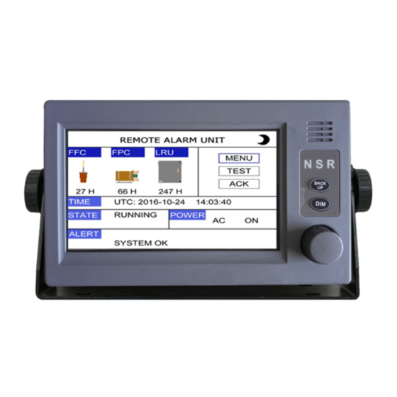
NVR-9000 & NVR-9000S USER MANUAL 2.2.1 Screen Components Actual Recording hours/ requirement Time Mode Power Status Alarm message Item Symbol Meaning Time Mode UTC time Local time State Status RUNNING Normal status BACKUPING Back up status Stop Stop status Power Status... -
Page 19: Screen Dimmer
NVR-9000 & NVR-9000S USER MANUAL 2.2.2 Screen dimmer There are two ways to adjust the brightness and contrast of the LCD. ① Adjust the brightness in the [SYSTEM SETTING]. ② Press the DIM button to adjust the brightness. Note: When the power is turned off, the last status of brightness is stored. Therefore when the power is turned on again, the screen will display with the last brightness before powered off. - Page 20 NVR-9000 & NVR-9000S USER MANUAL VIU: Status of Video Acquisition Unit MIC: Status of Microphone channels DAU: Status of Data Acquisition Unit DEU1: Status of Data Extension Unit1 Status Indication: - : Related recording function of the channel is not in use...
-
Page 21: Data Backup
NVR-9000 & NVR-9000S USER MANUAL 2.3.2 Data Backup This function is to back up the stored data in VDR to the USB memory in DAU. Choose the data source among LRU/FFC/FPC to be backed up. And the time length can be set to 1h/2h/12h. -
Page 22: Alarm Message
NVR-9000 & NVR-9000S USER MANUAL 2.3.3 Alarm Message Select [ALARM MESSAGE] at [MENU]. The alarm messages are listed with the time generated, whether acknowledged or not, and alarm contents. The acknowledged alarm event will be marked with √ on that column. It will take approximately 3 seconds. -
Page 23: Diagnostics
NVR-9000 & NVR-9000S USER MANUAL 2.3.4.2 ALARM BUZZER Click the [ALARM BUZZER] to switch the alarm buzzer on or off. By setting the [ALARM BUZZER], alarm that sounds against system faults and message receiving may be enabled or disabled. 2.3.4.3 LANGUAGE The default menu language is English. -
Page 24: Service
NVR-9000 & NVR-9000S USER MANUAL 2.3.5.2 LCD TEST Press DIM to test the Display Brightness. 2.3.5.3 KEY TEST When any key is clicked, the box corresponding to the key will be filled with blue color. Press [EXIT] 3 times consecutively to return to a higher menu. - Page 25 NVR-9000 & NVR-9000S USER MANUAL 2.3.6.2 COM MONITOR It’s to check the communication sentences on the I/O ports. 2.3.6.3 Factory Set It’s to restore the system setting as factory settings. NVR-9000 & NVR-9000S UM.E 20200220-11...
-
Page 26: System Performance Test
NVR-9000 & NVR-9000S USER MANUAL Note: Please remember all settings will be cleared if this function is executed. 2.3.6.4 Reboot Click “REBOOT” to reboot the remote alarm unit. 2.4 System Performance Test Click the “TEST” to initiate the system performance test. The system performance test checks the power supplies, microphones, image and data recording functions. -
Page 27: Alarm Message
NVR-9000 & NVR-9000S USER MANUAL 2.5 Alarm Message NO. ALARM MESSAGE MEANING Trouble Shooting (Incomplete) 001 ALARM_NO_SYS_OK System Run OK DAU to RAU Communication 002 ALARM_NO_RAU_LOST Check DAU-RAU Cable Lost DAU to RAU Communication 003 ALARM_NO_DAU_LOST Check DAU-RAU Cable Lost... - Page 28 NVR-9000 & NVR-9000S USER MANUAL 026 ALARM_NO_VIU2_LOST VIU2 Lan Connection Lost Check VIU2 Lan and Power Cable 027 ALARM_NO_VIU3_LOST VIU3 Lan Connection Lost Check VIU3 Lan and Power Cable 028 ALARM_NO_VIU4_LOST VIU4 Lan Connection Lost Check VIU4 Lan and Power Cable...
- Page 29 NVR-9000 & NVR-9000S USER MANUAL 055 ALARM_NO_DAU_COM1_LOST DAU COM1 LOST Check DAU COM1 Port Connection 062 ALARM_NO_DAU_COM8_LOST DAU COM8 LOST Check DAU COM8 Port Connection 063 ALARM_NO_DEU1_COM1_LOST DEU1_COM1_LOST Check DEU1 COM1 Port Connection 078 ALARM_NO_DEU1_COM16_LOST DEU1_COM16_LOST Check DEU1 COM16 Port Connection...
-
Page 30: Data Recording Units
NVR-9000 & NVR-9000S USER MANUAL 3. DATA RECORDING UNITS Portable USB disk in the NVR-9000 is mandatory peripheral for proper operation of the VDR system. Removal, stealing, unauthorized possession or illegal usage of the disk drive is strictly forbidden. 3.1 Backup of Recorded Data When there is requirement to back up the last recorded data, the data can be manually saved to the USB flash stick. -
Page 31: Long-Term Recording Unit (Lru)
SSD in NVR9001 DAU. For NVR-9000 VDR, LRU has memory size of 512GB. Prior to abandon ship, the recorded data can be manually saved to the USB flash stick or just take away the LRU (SSD) instead. The LRU (SSD) can be physically removed from the Data Acquisition Unit by following the below procedure. - Page 32 NVR-9000 & NVR-9000S USER MANUAL Step 1: Find the drawbar in the photo below Step2: Pull out the drawbar to release the two belts. Step 3: Lift the FPC by two handles. NVR-9000 & NVR-9000S UM.E 20200220-11...
-
Page 33: Data Playback
Copy the software to the computer which the playback shall operate on. Double click on the “NVR-9000 Playback Software” icon to start the application. If the recorded data has been copied to the computer, the data can be played back directly. If the data is not downloaded, connect the playback computer to the VDR with the LAN cable to the “DATA”... - Page 34 NVR-9000 & NVR-9000S USER MANUAL Playback page will appear in the next window: Open and Download menu are located on the top right corner of the page. Download: Download data to the desired directory Open: Open the data in the selected directory.
-
Page 35: Download The Data
NVR-9000 & NVR-9000S USER MANUAL 4.3 Download the Data Click on the DOWNLOAD menu and the following page is displayed. NVR-9000 & NVR-9000S UM.E 20200220-11... - Page 36 NVR-9000 & NVR-9000S USER MANUAL Set Start date and time of data to be downloaded Set End date and time of data to be downloaded Select Data source from: - Float-Free Capsule (FFC) - Fixed Protective Capsule (FPC) or - Long-term Data Recording Unit (LRU).
-
Page 37: Open The Data File
NVR-9000 & NVR-9000S USER MANUAL 4.4 Open the Data File When the data had been download or saved in the destination file, playback procedure as follows: Click on OPEN menu; Choose the File to be playback. (File name format: YYYY/MM/DD), click on OK Click on to playback the data;... -
Page 38: Playback Operation Menu
NVR-9000 & NVR-9000S USER MANUAL 4.5 Playback Operation Menu Open a data file: Download a data file: Help menu: Data playback period: Selects Audio Channel: Main Interface page: IEC 61162 Serial Data: Digital Data: Analog Data: Displays Radar Image/ECDIS: Door Info: AIS: NVR-9000 &... -
Page 39: Main Interface
NVR-9000 & NVR-9000S USER MANUAL 4.5.1 Main Interface Main Interface page displays the following standard information: Wind Depth Heading Speed Rudder Steering Order and response Engine Order and response Thruster ... -
Page 40: Digital Data
NVR-9000 & NVR-9000S USER MANUAL VDRPlayer Serial Data DAU COM1~COM8 S1~S8 DEU1 COM1~COM16 S9~S24 DEU2 COM1~COM16 S25~S40 DEU3 COM1~COM16 S41~S56 DEU4 COM1~COM16 S57~S72 4.5.3 Digital Data Digital Data records the change of the state, and the meaning of. The status with 0 and 1 to... - Page 41 NVR-9000 & NVR-9000S USER MANUAL indicate. Switch "1" represents the input of the closed state (dry contact) and high level (wet contacts), at this moment the LED on the board next to the switch interface is bright. Switch "0" represents the open circuit state (dry contact) and low level (wet contact), at this time the LED on the board next to the switch interface board is off.
-
Page 42: Analog Data
NVR-9000 & NVR-9000S USER MANUAL When CH2 is 0 displays CH1 Run, at the same time time lights out, followed by the name of the equipment. 4.5.4 Analog Data Analog Data displays status of the analog signals. Analog Data includes PointValue, proprty (Voltage and current), Value and Unit. - Page 43 NVR-9000 & NVR-9000S USER MANUAL The amount of species simulated by the jumper cap to select input, can choose Current or Voltage. Configuration software: Below the Analog table, there are Channel, Description, Property and so on. Channel:Corresponding to the A001-A008 DEU expansion box. (Note: Because of the analog interface in the expansion enclosure is only 8, so please don't add more than 8 devices.)
- Page 44 NVR-9000 & NVR-9000S USER MANUAL Unit:Actual unit of equipment. Such as degree ( °). Equipment: User connected device. Calibration point1, Calibration point1 value, Calibration poin2, Calibration point2 value: The purpose of analog calibration is to convert the analog quantity of the actual input to the physical quantity to be displayed.
-
Page 45: Radar Image/Ecdis
NVR-9000 & NVR-9000S USER MANUAL 4.5.5 Radar Image/ECDIS Radar Image Radar page displays the recorded radar image during the period of playback. Radar image from 4 different radars can be selected for playback. Only 1 radar image from the selected radar sensor is displayed at a time. - Page 46 NVR-9000 & NVR-9000S USER MANUAL NVR-9000 & NVR-9000S UM.E 20200220-11...
-
Page 47: Interface
Accelerations and hull stresses √ Wind speed and direction √ Any other equipment providing data in IEC61162 Format √ Serial Data received by NVR-9000/NVR-9000S is in NMEA format as defined in the IEC61162 and IEC61996 standards. NVR-9000 & NVR-9000S UM.E 20200220-11... - Page 48 NVR-9000 & NVR-9000S USER MANUAL Parameter to be recorded Sentence format Date and time Ship’s position and datum used GNS, DTM, GLL, GGA, RMC, NSR Speed (water and/ or ground) VBW, VLW, VTG Heading (true) THS, HDT Heading (magnetic) Depth (echo sounder)
-
Page 49: Maintenance
NVR-9000 & NVR-9000S USER MANUAL 6. MAINTENANCE 6.1 Fuse Replacement After opening the DAU, you will see the fuses behind the door. 3A for Battery and 5A for the AC power. If the fuse blown, choose the right fuse to replace. Remove the shelter on the PCB boards, find the Main Power or the BATT. -
Page 50: Consumable Parts
NVR-9000 & NVR-9000S USER MANUAL 6.2 Consumable Parts The lifetimes of consumable parts can be seen in below table: LOCATION PART NAME PART NO EXPIRY *Note NVR9001/DAU Backup Battery Pack NBT900 4 years NFP-2000C/FPC Beacon DKM502/90 3 years Battery Pack... -
Page 51: Specifications
NVR-9000 & NVR-9000S USER MANUAL 7. SPECIFICATIONS 7.1 Specifications Item Specification Ethernet IEC61162-450 2 ch Serial IEC61162-1/2 8 ch VHF Audio 2 ch Interface Microphone 8 ch Remote Alarm Unit 1 ch 1 ch Data Acquisition Unit (DAU) Remote Alarm Unit (RAU) -
Page 52: Power Supply
NVR-9000 & NVR-9000S USER MANUAL 7.2 Power Supply Item Specification Data Acquisition Unit (DAU) AC100V/220V, 0.5~1.5A, 50/60Hz Data Extension Unit (DEU) DC24V, 0.5A Video Interface Unit (VIU) DC24V, 0.3A 7.3 Equipment List Part No Description NVR-9000 VDR NVR-9000S SVDR NVR9001 Data Acquisition Unit (DAU)... -
Page 53: Appendix Neb-2000C-Vdr User's Manual
NVR-9000 & NVR-9000S USER MANUAL APPENDIX NEB-2000C-VDR User’s Manual NVR-9000 & NVR-9000S UM.E 20200220-11... - Page 54 USER MANUAL EPIRB & Float-free Capsule NEB-2000C-VDR NEB-2000C-VDR UM.E 20200220-06...
- Page 55 General Information i. Copyright The entire contents in this user manual, including any future updates, revisions, and modifications, shall remain the property of NSR at all times. Unauthorized copies or reproduction of this manual, either in part or whole, in any form of print and electronic media, is prohibited. The contents herein can only be used for the intended purpose of this manual.
- Page 56 MODIFY RECORD Modify by Date Paragraph Version Reason 2015/11/19 First edition 2015/12/22 Photos replaced 2017/03/06 Product improvement 2018/06/19 Cover modification 2018/12/27 General modification 2020/02/20 General modification NEB-2000C-VDR UM.E 20200220-06...
- Page 57 Table of Contents 1. DESCRIPTION ............................ 1 1.1 PRODUCT OVERVIEW ......................1 1.2 COSPAS-SARSAT SYSTEM OVERVIEW ................2 1.3 FEATURES & COMPONENTS ..................3 1.4 SPECIFICATIONS ........................6 2. INSTALLATION ..........................7 2.1 MOUNTING ..........................7 2.2 PLACING ........................... 8 2.3 VDR CONNECTION .........................
-
Page 58: Description
NEB-2000C-VDR USER MANUAL 1. DESCRIPTION 1.1 PRODUCT OVERVIEW NEB-2000C-VDR consists of an EPIRB (beacon module) and a VDR memory module. The EPIRB/FFC is developed to meet the regulations and rules for use on ships, vessels and life rafts in the maritime service. -
Page 59: Cospas-Sarsat System Overview
NEB-2000C-VDR USER MANUAL 1.2 COSPAS-SARSAT SYSTEM OVERVIEW Operational use of Cospas-Sarsat by SAR agencies started with the crash of a light aircraft in Canada, in which three people were rescued (September 10, 1982). Since then, the System has been used for thousands of SAR events and has been instrumental in the rescue of over 33,000 lives worldwide. -
Page 60: Features & Components
NEB-2000C-VDR USER MANUAL LEOSAR GEOSAR Beacon identification information Beacon identification provided, and and location information provided location information available if encoded in beacon message (location protocol beacon) Global coverage, Near instantaneous alerting in the instantaneous GEOSAR coverage area 1.3 FEATURES &... -
Page 61: Components
NEB-2000C-VDR USER MANUAL 1.3.2 COMPONENTS Basically EPIRB/FFC is composed of container (with cable cutter) and beacon (with memory board). The main components are described as below: Outside Connector Hydrostatic Release Unit Antenna VDR Data cable Ejector Data Cable Cutter Switch Strobe LEDs Deactivation Magnet Lanyard... - Page 62 NEB-2000C-VDR USER MANUAL Switch: The slide switch is hided under the yellow cover. When off, the switch is left in the middle place as READY position. Press TEST button to test the beacon. Slide to ON position to manually activate the beacon. Water Sensor: Two bare copper contacts form into the water sensor.
-
Page 63: Specifications
NEB-2000C-VDR USER MANUAL 1.4 SPECIFICATIONS Model NEB-2000C-VDR Material ABS Plastic Beacon Color High visibility orange Waterproof ≥10 min under water of 10m General Buoyant Automatic hydrostatic release, Manual switch Deployment control Accessories Hydrostatic Release Unit / Lanyard Controls Manual activation / Self-Test switches Weight 1.8 kg Height... -
Page 64: Installation
NEB-2000C-VDR USER MANUAL 2. INSTALLATION Before installing the EPIRB/FFC, find a suitable mounting position on the vessel. It should be mounted upright against a vertical bulkhead. It is critical that you choose a position where the released beacon will not get trapped by overhangs, even in case that the vessel sinks. Mount the capsule by the below rules: Consider easy access in an emergency. -
Page 65: Placing
NEB-2000C-VDR USER MANUAL 2.2 PLACING Follow below steps to place the beacon into the container. Step 1. Install the data cable. Step 2. Bend the antenna along the pole of NHR-100. Step 3. Sit the beacon into the container. Step 4. “THIS SIDE UP”... -
Page 66: Vdr Connection
NEB-2000C-VDR USER MANUAL 2.3 VDR CONNECTION The FFC connects to VDR with junction box. NEB-2000C-VDR UM.E 20200220-06... -
Page 67: Operation
NEB-2000C-VDR USER MANUAL 3. OPERATION 3.1 ACTIVATION The beacon can be activated by two processes: automatic activation and manual activation. When activated, the beacon will behave in below steps. Step 1. LED test, all LED flash once one by one. Step 2. - Page 68 NEB-2000C-VDR USER MANUAL Summary of LED status in Activation BEACON STATE Strobe Light BATT LOW TX121 TX406 STATUS Normal TX: Flash TX: Flash Flash every 3 seconds Flash Flash every 3 seconds GPS receiving Flash every 3 seconds GPS fixed Flash every 3 seconds GPS standby Flash every 3 seconds...
-
Page 69: Automatic Activation
NEB-2000C-VDR USER MANUAL 3.2 AUTOMATIC ACTIVATION NEB-2000C-VDR is designed with float-free activation. It contains a spring-loaded ejector which automatically pushes the container cover off and releases the beacon if a vessel sinks. This automatic ejection is controlled by Hydrostatic Release Unit (NHR-100). The plastic pole is pulled out before the container reaches 4 meters depth. -
Page 70: Manual Activation
NEB-2000C-VDR USER MANUAL 3.3 MANUAL ACTIVATION If there is enough time when in distress, the beacon can be taken out from the container and brought to life raft. In such case, the beacon can be manually activated. Take the below steps to remove the beacon from the container: Pull out the lock pin and open the cover of container. - Page 71 NEB-2000C-VDR USER MANUAL NOTE: If the beacon stays near a metal wall or is held by the antenna with hand, the transmission will be affected. ①In the container. ②Take out of the container. ④ Activated and Keep Upright ③ Lift up the Cover and Slide On NEB-2000C-VDR UM.E 20200220-06...
-
Page 72: Test Mode
NEB-2000C-VDR USER MANUAL 3.4 TEST MODE 1) Leave the beacon in the container or hold the beacon in the hand. 2) Press the TEST button with a tool for 2 seconds to start self-test. 3) The test operation begins and last for about 15 seconds. 4) Status LED indicates the result of self-test. -
Page 73: Maintainance
NEB-2000C-VDR USER MANUAL 4. MAINTAINANCE 4.1 SELF TEST & INSPECTION As an important part of GMDSS, EPIRB should be checked regularly. NEB-2000C-VDR has a built-in test capability which can check the situation of the battery, strobe light, and both 406MHz and 121.5MHz distress transmitters. -
Page 74: Self Test
NEB-2000C-VDR USER MANUAL 4.1.1 SELF TEST It is recommended that the Self-Test should be taken every two months. To perform Self-Test, through the hole on the switch cover, use a tool to press and hold the TEST button for 2s, and then release the button. During Self-Test, the transmitting messages won’t be regarded as distress alert even received by satellite. - Page 75 NEB-2000C-VDR USER MANUAL Summary of LED status in Self-test BEACON STATE BATT Strobe Light TX121 TX406 STATUS Self-test OK Flash every 3 seconds Normal TX: Flash TX: Flash Flash every 3 seconds Flash every 3 seconds 406MHz failed Flash every 3 seconds 121.5MHz failed Flash every 3 seconds Battery low voltage...
-
Page 76: Important Notice
NEB-2000C-VDR USER MANUAL 4.1.2 IMPORTANT NOTICE The water sensor switch has two contacts exposed in air. The unexpected seawater or rainstorm at sea may make two contacts conducting. Even though, the magnetic bar on the ejector will keep the beacon from being activated. So, it’s very important to place the beacon in the container in proper direction and keep the container closed always, except for regular test or maintenance. -
Page 77: Replace Hru And Cable Cutter
NEB-2000C-VDR USER MANUAL 4.2 REPLACE HRU AND CABLE CUTTER The lifetimes of consumable parts can be seen in below table: PART NAME PART NO INTERVAL Battery Pack NBT400 5 years Hydrostatic Release Unit NHR-100 2 years Cable Cutter NCC-100 2 years NHR-100 hydrostatic release unit and NCC-100 cable cutter should be replaced every 2 years. -
Page 78: Replace Battery Pack
NEB-2000C-VDR USER MANUAL 4.3 Replace battery pack The expiry date is marked on the beacon body, and it should be checked regularly. NBT400 battery pack should be replaced when one of below cases happens: The beacon has been used in an emergency situation. A false activation exceeds 2 hours of use.
Need help?
Do you have a question about the NVR-9000 and is the answer not in the manual?
Questions and answers