
Related Manuals for Wfly ET16S


Summary of Contents for Wfly ET16S
- Page 1 Shenzhen WFLY Technology Development Co., LTD HOME/MON. EXIT/LOCK ET16S INSTRUCTION MANUAL (ET Series)16-channel Digital Proportional R/C System V1.00...
- Page 2 Thank you for using WFLY products! ● Please read this product manual carefully before using this product! ● Please use this product correctly! The model is not a toy, for safety,please don't fly in crowded places! ——Shenzhen WFLY Technology Development Co., LTD...
- Page 3 CATALOGUE \Safety Precautions Symbols Definition Flying Precautions Battery Headphone Port Trainer Port USB Port \Before Use Basic Configuration Product Features Each Parts Name Of Transmitter The Travel of Antenna Direction Adjustment Switch Configuration and Model Types \Basic Operation Home Interface Introduction 014-015 Touch Screen Operation Stick Adjustment...
- Page 4 CATALOGUE \System Setting Trainer Display User Name Sound Warning Low Battery Stick Mode Calibration Telemetry Voice Back Colour Language Screen Cali(Calibration) Data Reset Information Screen Lock Set \Linkage Setting Link Telemetry 043 044 Sensor Receiver Output Fail Safe Relay Flight Servo Frequency BUS Servo Setting Range Check...
- Page 5 CATALOGUE \Model Menu\Helicopter Condition Pitch Curve Throttle Curve Throttle Hold Throttle Cut Gyro Swash Ring Swash Mixing Throttle Mixing Idle Down Governor Pitch→Rudder Pitch→ Needle Fuel Mixes 081 082 Swash \Model Menu\Airplane Condition AIL Differential Throttle Curve Throttle Cut Throttle Hold Idle Down Aileron→Rudder Rudder→Aileron...
- Page 6 CATALOGUE \Model Menu\Glider Condition AIL Differential Throttle Curve Throttle Cut Throttle Hold Idle Down Aileron→Rudder Rudder→Aileron Flap Setting Camber Mix Elevator to Camber Flap to ELE Aileron to Flap Butterfly Trim Mixing Gyro Motor V-tail Aileron Elevator Winglet \Model Menu\Multicopte Condition Throttle Curve Throttle Cut...
-
Page 7: Safety Precautions
Before flying, inspect the aircraft carefully, User should be responsible for any consequences inspect whether the aircraft and transceiver system caused by using the product. WFLY shall not be it's normal. When flying, make the transmitter liable for any directly or indirectly damage, injury... - Page 8 IMPORTAN! Long term storage (more than 3 months),storage Transmitter (ET16S): temperature≤45°C general storage voltage 3.7- ET16S adopts the power supply mode of lithium 3.9v.Failure to follow the proceeding precautions battery, and the working voltage adapts to the range 注意 can quickly result in severe, permanent damage to of 3.5V-13V.
- Page 9 It is forbidden to insert the power supply (high voltage) terminal to the port to avoid damage for the transmitter. Suggestion: You can consult the purchase line at WFLY Technology Taobao Store or other model online stores or physical stores. USB Port...
-
Page 10: Before Use
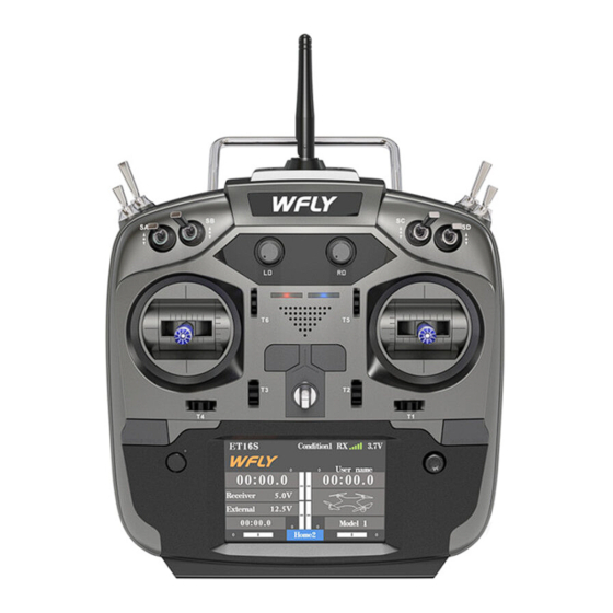
Wireless signal copy: model data External voltage detection: DC 0~96V External RF modules:Support Dimension: 47x14x25mm Hall gimbals Weight: 12g Basic Configuration ET16S transmitter x1 RF209S receiver x1(include external power detection line x1) Hanging strap x1 Summary manual x1 ③ ① ②... - Page 11 Before Use Each Parts Name Of Transmitter Antenna Carr y handle SF Switch Block SH Switch Block SE Switch Block SG Switch Block SB Switch Block SC Switch Block SA Switch Block SD Switch Block LD Rotary Knob RD Rotary Knob Power LED RF LED Trim6...
- Page 12 Before Use Switch configuration and model types Power LED: Left, power indicator light, red RF LED: Right, RF indicator light, blue. POWER: Click one power key only for 3 seconds to open/shut down; Click 2 power keys at the same time to flash shutdown.
-
Page 13: Basic Operation
Basic Operation Home Interface Introduction Conditionl1 RX ET16S 10.6V WFLY User name 0 0 : 0 0 . 0 0 0 : 0 0 . 0 Home Interface 1 Receiver 4.5V External 12.5V 0 0 : 0 0 . 0... -
Page 14: Touch Screen Operation
Basic Operation Touch Screen Operation ET16S uses 3.5 inches resistive touch screen, Parameters Setting which makes ET16S operation more flexible and 1 Data setting:Click and pop up the upper right efficient. setup key,press long for rapid add and subtract.Long Press the number button to reset the default value. - Page 15 Basic Operation Touch Screen Operation Popup prompt: Keyboard When the operation changes important The keyboard is only used for naming function, parameters, the selection box will pop up for such as model renaming, secondary confirmation. The default "No" is Flight condition naming, username setting. selected.
-
Page 16: Stick Adjustment
3. Twist the upper head clockwise to lock it Stick feel and function adjustment ET16S uses the newly developed four-bearing assembly to trim the feel! Uncover the silicone sheet on the back and adjust the feel directly. Note: Do not use excessive force or over twist the number of turns when adjusting the screw. Otherwise, the structure assembly would be twisted off and the screw may fall off, resulting in irreversible damage. - Page 17 If you need components such as bracket 5 (such as the parts needed for assembling double circuit structure!), you can e-mail to WFLY overseas seller to order the spare parts at sales@wflysz.com...
-
Page 18: Receiver Instructions
Basic Operation Receiver Instructions Receiver LED STATUS LIST Mode Action Status Purple PWM normal work mode USB port Green W.BUS normal work mode Blue PPM normal work mode Work No signal Slow flash Low voltage Orange Slow flash Linking Antenna Green Slow flash W.BUS mode Keep straight Blue Slow flash PPM mode... - Page 19 Basic Operation Receiver and servo connection example - Airplane The figure below shows an example of airplane connection. Please use the actual wing type and tail type for ser vo connection. CH1/Aileron CH2/Elevator CH3/Throttle CH4/Rudder Servo connection position (Airplane) CH5/Gear The table below shows examples of the servo connection positions for the different wing types CH6/FLP...
- Page 20 Basic Operation Receiver and servo connection example - Glider The figure below shows an example of glider connection. Please use the actual wing type and tail type for servo connection. CH1/Aileron CH2/Elevator CH3/Throttle CH4/Rudder Servo connection position (Glider) CH5/Gear The table below shows examples of the servo CH6/FLP connection positions for the different wing types and tail types.
- Page 21 Basic Operation Receiver and servo connection example - Helicopter The figure below shows an example of helicopter connection. Please use the actual wing type and tail type for servo connection. CH1/Aileron CH2/Elevator CH3/Throttle CH4/Rudder CH5/Gyro CH6/Pitch CH7/Aux/Governor Servo connection position (Helicopter) The table below shows examples of the servo connection positions for different swashes.
- Page 22 Basic Operation Receiver and servo connection example - Multicopter The figure below shows the four-rotor multicopter. Please refer to the model manual for specific applications. Motor,electronic speed controller, flight controller, battery, etc. are sold separately. Use 5CH-9CH when using accessories such as camera shutters.
- Page 23 Basic setting sequence of airplane and glider 1. Call of the model under [Model Menu] to set. After the flame out The ET16S transmitter has 30 built-in models function is activated and the corresponding switch from the factory, and you can use the [Model...
- Page 24 Basic Operation Basic setting sequence of the helicopter 1. Model addition and invocation each rudder surface. Please refer to the first part of the previous section "Basic Operation - Basic Settings of Fixed The swash calibration (except H-1 mode) can Wings and Gliders".
- Page 25 Basic Operation Basic setting sequence of the helicopter maximum in both the positive and negative pitch 10. Throttle Setting directions. For example, from -7 to +12° At the end of the flight, there is no need to 6. Throttle Hold Setting change the position of the throttle trim, just turn In the model menu, call the [Throttle Hold] off the engine by simply turning a flameout switch.
-
Page 26: System Setting
) Trainer Switch: Default [--] Channel Mode: default is "16 channel" setting; "8 channel mode" is compatible with WFLY training function of the "WFT" series products. The trainer’s two ET16Ss need to be set up to the same mode. - Page 27 System Setting Display Interface Path: WFLY → [System Setting] → [Display] Adjust the brightness of the display backlight, the shutdown time, and the lock screen time to adapt to different environments and energy saving. Display The backlight switches to the "Backlight max" value! Backlight max The darkest brightness value of normal standby.
- Page 28 System Setting User Name Interface path: WFLY → [System Setting] → [User Name] The user defied name is composed of up to 9 characters and supports English character input, which can be displayed on the standby interface. Conditionl1 RX ET16S 10.6V...
- Page 29 System Setting Sound Interface path: WFLY → [System Setting] → [Sound] The sound helps the flight process to notice various anomalies or planned audible prompts. The sound is associated with the model, and the prompt tone can be set according to the requirements of each model.
- Page 30 System Setting Warning Interface path: WFLY → [System Setting] → [Warning] After the function is turned on,there will a corresponding detection reminder when the power- on detection . Under setting conditions,there will be an interface, sound, and vibration prompts when the transmitter detection is in effect.
-
Page 31: Low Battery
System Setting Low Battery Interface path: WFLY → [System Setting] → [Low Battery] By setting the alarm trigger value, an alarm is given at low voltage. Avoid accidents caused by long-term operation of the control system under low voltage conditions... -
Page 32: Stick Mode
System Setting Stick Mode Interface path: WFLY → [System Setting] → [Stick Mode] Provides 4 operating mode options, in addition to the [Function] user defied the mode: You need to modify the definition in [Function]. After the modification, the [Stick Mode] interface mode changes to "User Defied".([Function] 1-4 channel stick setting) - Page 33 System Setting Calibration Interface path: WFLY → [System Setting] → [Calibration] The stick has been calibrated at the factory. If the center position of the stick changes,you need to use this function to calibrate the stick. Normal stick calibration User defined stick calibration Quich automatic calibration,for standard Full manual user-defined travel calibration,...
- Page 34 System Setting Telemetry Voice Interface path: WFLY → [System Setting] → [Telemetr y Voice] Set up telemetr y voice broadcast. Telemetry voice Status Switch Speed Interval of two broadcasts (broadcast frequency) Speed interval 30Sec The number of repetitions in each broadcast report...
- Page 35 System Setting Back Colour Interface path: WFLY → [System Settings] → [Back Colour] This function enables the background color sets and taps the option to change the settings. Back Colour Back Colour Black Back colour switching: The default is black, in order to adapt to the visual effects of different environments, you can switch to...
- Page 36 System Setting Language Interface path: WFLY → [System Setting] → [Language] Select the language displayed on the interface, ET16S provides Chinese and English display. Language Language English Language switching: Currently interface is Chinese,click the “Language” button and then the interface language will switch to...
- Page 37 System Setting Screen Cali(Calibration) Interface path: WFLY → [System Setting] → [Screen Cali] Depending on the characteristics of the resistive screen,the corresponding contacts may drift after prolonged use. It is therefore necessary to recalibrate the coordinate position of the touch point of the screen.
-
Page 38: Data Reset
System Setting Data Reset Interface path: WFLY → [System Setting] → [Data Reset] Reset the transmitter's selected parameter settings. The “ Factory Date Reset” operation is with large amount of data, please be patient when performing this operation. Data reset The models being used (Model Menu)data would be reset. - Page 39 2 WeChat PC side download. Log in to WeChat, open the "WFLY" WeChat official account, send the text "ET16S upgrade package", you will receive the download link of the latest upgrade toolkit, click the driver link, you can directly download and save to the PC.
- Page 40 System Setting Screen lock set Lock screen description: The user can set the lock screen corresponding operation mode according to the specific use scene or personal operation habits, so as to avoid accidental operation and change the remote controller parameters. Screen lock set Touch Cursor...
-
Page 41: Linkage Setting
Range detection: ACT and INH the range set); detection function. 3. There is no other WFLY 2.4GHz Fail safe:1. Function is off. 2. Receiver control. 3. system in progress. Do not set. 4. Keep the last move. 5, User defined, 4. - Page 42 Linkage Setting Telemetry Interface path: WFLY → [Linkage Setting] → [Telemetry] The telemetry interface displays the receiver's return data. 1,Turn on the built-in tuner and turn off the external tuner. Telemetry Receiver 3.7V Disabling the "Telemetry" function External when linking will affect the use of 注意...
- Page 43 Linkage Setting Sensor Interface:WFLY→[Linkage setting]→[Sensor] Configure sensor parameters. Valid parameters will be displayed on the telemetry interface. With low signal warning function, the custom sensor options can be created, please refer to the module manual for details. Sensor RSSI Received signal strength indicator,the unit is dB.
- Page 44 Linkage Setting Sensor battery. 8. Power consumption: based on the current sensor value. 9. Distance: The distance between the model player and the model plane. If the altitude source is set, the distance is the distance between the module and the aircraft in the air. If no set the altitude source, it is the distance from the module player to the aircraft vertical ground position.
-
Page 45: Receiver Output
Linkage Setting Receiver Output Interface path: WFLY → [Linkage Setting] → [Receiver Output] This function is used to customize the port output function channel of the receiver. For the corresponding channel function, please go to [Function] of [General Menu] to set. - Page 46 Linkage Setting Fail Safe Interface path: WFLY→ [Linkage Setting] → [Fail Safe] With this function, when the receiver cannot receive the signal normally, it will automatically run, and the servo rocker arm will move to the preset position (preset action). Used to protect aircraft and reduce unnecessary losses.
- Page 47 Linkage Setting Relay Flight Interface path: WFLY → [Linkage Setting] → [Relay Flight] This function is a flight control mode that uses two transmitters, two receivers, and one model aircraft to achieve long-distance relay control. The main and the sub-transmitter are linked seperately with the receiver, the eighth pin header (PPM/W.BUS) of the sub-receiver RF209S connect with the ninth pin header...
- Page 48 Linkage Setting Servo Frequency Interface path: WFLY → [Linkage Setting] → [Servo Frequency] When using the digital servo, adjust the receiver output frequency to match the operating frequency of the servo to better play the servo performance. Adjust the output frequency of the receiver, the stroke is 50Hz~300Hz, and the setting is successful when exiting.
- Page 49 Interface path: WFLY → [Linkage Setting] → [BUS Servo Setting] The BUS servo can memorize its own channel and different settings. The servo can be configured on the ET16S by connecting the servo via the W.BUS2 receiver interface. (WFLY W.BUS system is compatible with S.BUS servos !)
-
Page 50: Range Check
Linkage Setting Range Check Interface path: WFLY → [Linkage Setting] → Range Check [Range Check] The range checkt is mainly used to test the Pull the switch(SH) to reduce the distance. power of transmitter. Turn on the telemetry when linking. After linked,... -
Page 51: Telemetry Unit
Linkage Setting Telemetry Unit Interface path: WFLY → [Linkage Setting] → [Telemetry Unit] Set the unit for telemetry display. Telemetry unit Length Metric Fahrenheit Temp. Unit switching instructions: For the length unit, click the unit name button on the right to switch. There are “metric” and “imperial”... - Page 52 Linkage Setting 180/270°Servo Interface path:[WFLY]→[Linkage Setting] → [180 / 270 ° Servo] The 180/270° servo is the setting of the rotary stroke of the large rudder angle servo, which is disabled by default. It is generally used in the setting of a large amount of servo such as a tank or a robot.
-
Page 53: General Menu
General Menu Monitor Interface path: WFLY → [General Menu] → [Monitor] This interface can be used to understand the servo output of each channel and confirm the servo action. It can also perform the servo test, such as “stroke” and “Midpoint Test”. -
Page 54: Model Select
General Menu Model Select Interface path: WFLY → [General Menu] → [Model Select] The ET16S can store 30 sets of model data and can flexibly edit the information of the processed data set. Model select Model select Current model cumulative time... -
Page 55: Model Type
General Menu Model Type Interface path: WFLY → [General Menu] → [Model Type] Airplanes and gliders are available in 6 main wing types and three tail types. Helicopters can choose from six swash types. There is a default preset for each type of model data. - Page 56 General Menu Function Interface path: WFLY → [General Menu] → [Function] When selecting the model and wing type, the servo output channel and function combination has been preset. If necessary, you can change the servo output. The combination of the road, functions (ailerons, elevators, etc.), control (stick JI-J4, switch SA-SH, trimming T1-T6, lever) and corresponding trimming can be customized.
-
Page 57: Servo Reverse
General Menu Servo Reverse Interface path: WFLY → [General Menu] → [Servo Reverse] This function reverses the direction of motion of each channel servo. For helicopters with a swash structure (HR-3, etc.), first use [Servo Reverse] to match the direction of the pitch servo, and then use the swash AFR function to set the direction of the ailerons and elevators. - Page 58 General Menu Dual Rate Interface path: WFLY → [General Menu] → [Dual Rate] The function can set the rudder angle end point and action curve of CH1-CH16 channel, which can be adjusted separately for each condition. This function is usually used after setting the servo stroke. When mixing is applied from one channel to another, both channels can use the [Dual Rate] function to change the operating ratio.
-
Page 59: End Point
General Menu End Point Interface path: WFLY → [General Menu] → [End Point] This function can adjust the end point on the left and right sides of the servo respectively, for correction on the machine body connection. The end point on the left and right sides can be 30%-155% (CH1-CH16), and the default value is 100%. - Page 60 General Menu Timer Interface path: WFLY → [General Menu] → [Timer] This timer function can be used for a variety of timings such as the total flight duration and the specific time of the game. Timer 1 and Timer 2 can be set and displayed on the main standby screen.
-
Page 61: Trim Setting
General Menu Trim Setting Interface path: WFLY → [General Menu] → [Trim Setting] In this function, you can set the amount of digital trim and the action mode, and you can select the trim step movement under each condition, or trim the individual movement under each condition. (For example, hover and stunt can be trimmed separately.) - Page 62 General Menu Sub-trim Interface path: WFLY → [General Menu] → [Sub-trim] This function is a function to trim the neutral position of each servo. In addition, the neutrality of the rudder surface can be trimmed while the connecting rod is connected.
-
Page 63: Channel Delay
General Menu Channel Delay Interface path: WFLY → [General Menu] → [Channel delay] This function is mainly used for realistic actions, such as retracting the undercarriage (reducing the response speed of the output channel), setting the stroke to 0 to 100, and the default is 0 (corresponding to the delay time of the channel stick position from one end to the other end is the set time). - Page 64 General Menu Program Mixes Interface path: WFLY → [General Menu] → [Program Mixes] It can create 10 mixing combinations, which can be customized by selecting channels or switch knobs, and supports mixing of 3 curve types (EX1, EXP2, and polyline). In addition to being used to create a variety of aircraft flight characteristics, it can be used for a variety of other purposes.
-
Page 65: Flight Mode
General Menu Flight Mode Interface path: WFLY → [General Menu] → [Flight Mode] This function can be combined by two arbitrary switches or knobs, rockers, etc. to form up to 9 different ratios of output. Each output user can set it according to actual needs, which is suitable for some flight control boards for various flight conditions. - Page 66 General Menu Double engine Interface path: WFLY → [General Menu] → [Double Engine] The output channels of Engine 1 and Engine 2 need to be set in the [General Menu] - [Function] menu. When part of the model aircraft, ship model, and car model use two motors as the power drive, the dual engine function can be directly used, and the engine 1, the acceleration rocker and the steering stick of the engine 2, and the engine 1 and the engine 2 can be simply set.
-
Page 67: Model Menu\Helicopter
Model Menu\Helicopter Condition Interface path: WFLY → [Model Menu] → [Condition] With this function, flight conditions can be configured as needed, and there are 5 flight conditions to choose from. If you do not need to use the conditional switching function, you do not have to set it on this page. The default configuration can be used directly. -
Page 68: Throttle Curve
Model Menu\Helicopter Throttle Curve Interface path: WFLY → [Model Menu] → [Throttle Curve] Through the 13-point curve, the throttle output curve is adjusted for the action of the throttle stick to achieve the optimal flight state of the engine (motor). -
Page 69: Pitch Curve
Model Menu\Helicopter Pitch Curve Interface path: WFLY → [Model Menu] → [Pitch Curve] This function adjusts the pitch curve for each "flight condition" to get the best flight status following the throttle stick action. Flight conditions: Set the "Flight Condition" control switch in [Model Menu] → [Condition]. Switching by the switch, the function curve setting is performed separately. -
Page 70: Throttle Hold
Model Menu\Helicopter Throttle Hold Interface path: WFLY → [Model Menu] → [Throttle Hold] This function sets the throttle in the cut position during landing. The throttle servo speed can be adjusted. Note: The throttle hold is associated with flight conditions and the throttle hold function must be set separately with different flight conditions. - Page 71 Model Menu\Helicopter Throttle Cut Interface path:WFLY→ [Model Menu]→[Throttle Cut] Safely and easily to turn off the engine. Throttle cut provides an easy way to stop the engine from running. Generally speaking, it can be realized by dialing a hardware switch in an idle state. This function cannot be triggered when the throttle is high to prevent any mis-operation.
- Page 72 Model Menu\Helicopter Gyro Interface path: WFLY → [Model Menu] → [Gyro] This function is used to adjust the gyroscope sensitivity. Set the sensitivity and mode of operation (normal/AVCS) for each flight condition or switch. Generally, when only the normal AVCS(lock tail) application is applied, it is only necessary to set a set of gyroscopes.
-
Page 73: Swash Ring
Model Menu\Helicopter Swash ring Interface path: WFLY → [Model Menu] → [Swash ring] This function limits the travel of the swash to a certain range to prevent damage to the swash end point when operating the ailerons and elevators at the same time. The maximum output rudder angle position can be obtained, which is suitable for settings such as 3D flight. -
Page 74: Swash Mixing
Model Menu\Helicopter Swash mixing Interface path: WFLY → [Model Menu] → [Swash Mixing] The swash mixing is used to correct the swash movement in the aileron (rolling) direction and the elevator (helicopter head pitch) according to the specific operation under each flight condition. -
Page 75: Throttle Mixing
Model Menu\Helicopter Throttle mixing Interface path: WFLY → [Model Menu] → [Throttle Mixing] This function is used to correct the effect of the swash on the engine when operating the aileron or elevator. In addition, there is a certain correction effect on the torque of the left/right rotation when the spinning. - Page 76 Model Menu\Helicopter Idle Down Interface path: WFLY → [Model Menu] → [Idle Down] The idle down is usually used when landing. By operating a switch, the engine speed can be reduced. This feature is only available when the throttle position is low.
- Page 77 Model Menu\Helicopter Governor Interface path: WFLY → [Model Menu] → [Governor] This function is used to switch the speed of the helicopter rotor head. The helicopter head speed can be switched by a hardware switch for each flight condition. Governor The control governor can be activated by "Flight Condition"...
- Page 78 Model Menu\Helicopter Pitch to Rudder Interface path: WFLY → [Model Menu] → [Pitch to Rudder] This mixing can be used due to the change in the main paddle torque caused by the reduced pitch operation. Adjusting the direction of the rudder keeps the nose from moving. If the gyro has a correction operation function, it is not necessary to use the mixing function.
- Page 79 Model Menu\Helicopter Pitch to Needle Interface path: WFLY → [Model Menu] → [Pitch to Needle] This multiple control is used for engines where the oil needle can be adjusted during flight (oil/gas mixture ratio adjustable). You can set an oil needle cur ve.
- Page 80 Model Menu\Helicopter Fuel Mix Interface path: WFLY → [Model Menu] → [Fuel Mix] The function is used to improve the mix control of engine needle adjust and control carburetor during flying. Engine cut setting This function is connected to the [Throttle Hold] function, the [Throttle Cut] function, and the [Idle Down] function.
- Page 81 Model Menu\Helicopter Swash Interface path: WFLY → [Model Menu] → [Swash] Swash link correction function (except swash H-1 mode) Midpoint position: This Neutral Point Setting function sets the midpoint correction point for the connection if the servo rocker arm is offset by the midpoint when the connection is installed. In addition,...
- Page 82 Model Menu\Helicopter Swash Neutral point setting process (setting the reference point of the correction function) 1. Adjust the stick arm of the servo to make the mid-point within 50% so that the mixing value is as small as possible. 2. Move the cursor to “midpoint position” and click to get (Not support button setting) to read the throttle stick position (rudder neutral point value).
- Page 83 Model Menu\Airplane Condition Interface path: WFLY → [Model Menu] → [Condition] With this function, flight conditions can be configured as needed, and there are 5 flight conditions to choose from. If you do not need to use the conditional switching function, you do not have to set it on this page. The default configuration can be used directly.
-
Page 84: Ail Differential
Model Menu\Airplane AIL Differential Interface path: WFLY → [Model Menu] → [AIL Differential] When the ailerons are controlled by two servos, the ratio of the upper and lower rudder angles of the left and right ailerons can be independently adjusted. -
Page 85: Throttle Curve
Model Menu\Airplane Throttle Curve Interface path: WFLY → [Model Menu] → [Throttle Curve] This function adjusts the action curve of throttle channel to optimize the power of throttle stick input. Throttle curve Type Offset +50% RATE +38% EXP2 +150 +100... -
Page 86: Throttle Cut
Model Menu\Airplane Throttle Cut Interface path:WFLY→ [Model Menu]→[Throttle Cut] Safely and easily to turn off the engine. Throttle cut provides an easy way to stop the engine from running. Generally speaking, it can be realized by dialing a hardware switch in an idle state. This function cannot be triggered when the throttle is high to prevent any mis-operation. -
Page 87: Throttle Hold
Model Menu\Airplane Throttle Hold Interface path: WFLY → [Model Menu] → [Throttle Hold] This function sets the throttle in the cut position during landing. The speed of the throttle servo can be adjusted. Note: The throttle hold is associated with flight conditions and the throttle hold function must be set separately with different flight conditions. - Page 88 Model Menu\Airplane Idle Down Interface path: WFLY → [Model Menu] → [Idle Down] The idle down is usually used when landing. By operating a switch, the engine speed can be reduced. This feature is only available when the throttle position is low.
-
Page 89: Aileron To Rudder
Model Menu\Airplane Aileron to Rudder Interface path: WFLY → [Model Menu] → [Aileron to Rudder] This function is required when mixing the rudder and ailerons. This feature allows the model to tilt to a steeper angle. Winglet Aileron to rudder... -
Page 90: Rudder To Aileron
Model Menu\Airplane Rudder to Aileron Interface path: WFLY → [Model Menu] → [Rudder to Aileron] This function is required when mixing ailerons and rudders. This function is used when the rudder is used for roll, such as side flying. Can also be applied to tilting or turning in a real machine, large model or full size... - Page 91 Model Menu\Airplane Rudder to Elevator Interface path: WFLY → [Model Menu] → [RUD to elevator] This function is used to mix the elevator and rudder operation. Used to correct unexpected movement trends when the rudder is used in a flight such as a roll or side fly.
- Page 92 Model Menu\Airplane Snap Roll Interface path: WFLY → [Model Menu] → [Snap roll] This function uses a selected control switch to perform fast cross-rolling and adjusts the ratio of ailerons, elevators and rudders. Snap roll Snap roll Mode Single Mode...
-
Page 93: Flap Setting
Model Menu\Airplane Flap Setting Interface path: WFLY → [Model Menu] → [Flap Setting] Each flap's up and down motion stroke can be individually adjusted for each servo according to the type of wing. * This function is only available for models with flaps. -
Page 94: Camber Mix
Model Menu\Airplane Camber Mix Interface path: WFLY → [Model Menu] → [Camber mix] This function is used to adjust the operating ratio on the positive and negative directions (ailerons, flaps) of the airfoil flaps. The ratio of the ailerons, flaps, and elevators can be individually adjusted to correct for changes in attitude caused by airfoil operations. -
Page 95: Ele To Camber
Model Menu\Airplane ElE to Camber Interface path: WFLY → [Model Menu] → [ElE to Camber] Use this functon when you need to mix flap operation and elevator operation. When the mixing control is turned on, the elevator will be raised while the flap is lowered, which can increase the lift. - Page 96 Model Menu\Airplane Camber Flap to Elevator Interface path: WFLY → [Model Menu] → [Camber flap to ELE] When using flaps, the pitch angle of the model has a tendency to change. This mixing compensates for the attitude change of the model by combining the inputs of the elevator.
- Page 97 Model Menu\Airplane Aileron to Camber Flap Interface path: WFLY → [Model Menu] → [Aileron to Camber Flap] This mixing uses the aileron mode to operate the flaps. When the aileron stick is operated, both the aileron and the flap operate simultaneously in the aileron mode, which can improve the characteristics of the snap roll operation.
- Page 98 Model Menu\Airplane Airbreak Interface path: WFLY → [Model Menu] → [Airbreak] This function is used to increase the resistance of the model when diving or landing. The preset elevator and flap offset values can be activated via the control switch. The offset rates of the ailerons, elevators, and flap servos can be adjusted as needed.
- Page 99 Model Menu\Airplane Gyro Interface path: WFLY → [Model Menu] → [Gyro] This function is used to adjust the gyroscope sensitivity. Set the sensitivity and mode of operation (normal/AVCS) for each flight condition or switch. Generally, when only the normal AVCS(lock tail) application is applied, it is only necessary to set a set of gyroscopes.
- Page 100 Model Menu\Airplane Motor Interface path: WFLY → [Model Menu] → [Motor] This function allows you to set the speed of the motor after the motor has been activated by a switch. Two ranges of operating speeds, slow flight and high speed flight (speed 1 / speed 2) can be set. This function can also be operated as a safety function by programming to a control switch.
- Page 101 Model Menu\Airplane Fuel Mix Interface path: WFLY → [Model Menu] → [Fuel Mix] This function is used to improve the mixed control of engine needle control carburetor during flight. Engine cut setting This function is connected to the [Throttle hold] function, the [Throttle Cut] function, and the [Idle Down] function.
- Page 102 Model Menu\Airplane Elevator Interface path: WFLY → [Model Menu] → [Elevator] If the aileron type is selected in the model type selection function of the context menu and the aileron type is selected in the tail type, the elevator of the aileron elevator tail type can be adjusted in this setting interface.
- Page 103 Model Menu\Airplane V-Tail Interface path: WFLY → [Model Menu] → [V-Tail] If the tail type is "V-tail" which is selected from the model type selection of the context menu, the elevator and rudder of the V-tail can be adjusted in this interface. (The V-tail uses two servos to control the rudder at the same time.
- Page 104 Model Menu\Airplane Winglet Interface path: WFLY → [Model Menu] → [Winglet] This function is used to adjust the left and right rudder of the model winglet. The winglet is used to reduce the induced drag caused by the wing tip vortex. (Winglets are vertical or angled extensions at the end of each wing.)
- Page 105 Model Menu\Glider Condition Interface path: WFLY → [Model Menu] → [Condition] With this function, flight conditions can be configured as needed, and there are 5 flight conditions to choose from. If you do not need to use the conditional switching function, you do not have to set it on this page. The default configuration can be used directly.
- Page 106 Model Menu\Glider AIL Differential Interface path: WFLY → [Model Menu] → [AIL Differential] When the ailerons are controlled by two ser vos, the ratio of the upper and lower rudder angles of the left and right ailerons can be independently adjusted.
-
Page 107: Throttle Curve
Model Menu\Glider Throttle Curve Interface path: WFLY → [Model Menu] → [Throttle Curve] This function adjusts the action curve of the throttle channel to optimize the corresponding power level when the throttle stick is input. Throttle curve Type Offset RATE... -
Page 108: Throttle Cut
Model Menu\Glider Throttle Cut Interface path:WFLY→ [Model Menu]→[Throttle Cut] Safely and easily to turn off the engine. Throttle cut provides an easy way to stop the engine from running. Generally speaking, it can be realized by dialing a hardware switch in an idle state. This function cannot be triggered when the throttle is high to prevent any mis-operation. -
Page 109: Throttle Hold
Model Menu\Glider Throttle Hold Interface path: WFLY → [Model Menu] → [Throttle Hold] This function sets the throttle in the cut position during landing. The throttle servo speed can be adjusted. Note: The throttle lock is associated with flight conditions and the throttle lock function must be set separately with different flight conditions. - Page 110 Model Menu\Glider Idle Down Interface path: WFLY → [Model Menu] → [Idle Down] The idle down is usually used when landing. By operating a switch, the engine speed can be reduced. This feature is only available when the throttle position is low.
- Page 111 Model Menu\Glider Aileron to Rudder Interface path: WFLY → [Model Menu] → [Aileron to Rudder] This function is required when mixing the rudder and ailerons. This feature allows the model to tilt to a steeper angle. Aileron to rudder Functional status...
- Page 112 Model Menu\Glider Rudder to Aileron Interface path: WFLY → [Model Menu] → [Rudder to Aileron] This function is required when mixing ailerons and rudders. This function is used when the rudder is used for roll, such as side flying. Can also be applied to tilting or turning in a real machine, large model or full size model.
- Page 113 Model Menu\Glider Flap Setting Interface path: WFLY → [Model Menu] → [Flap Setting] Each flap's up and down motion stroke can be individually adjusted for each servo according to the type of wing. * This function is only available for models with flaps.
- Page 114 Model Menu\Glider Camber Mix Interface path: WFLY → [Model Menu] → [ Camber Mix This function is used to adjust the operating ratio on the positive and negative directions (ailerons, flaps) of the airfoil flaps. The ratio of the ailerons, flaps, and elevators can be individually adjusted to correct for changes in attitude caused by airfoil operations.
- Page 115 Model Menu\Glider Elevator to Camber Interface path: WFLY → [Model Menu] → [Elevator to Camber] Use this functon when you need to mix flap operation and elevator operation. When the mixing control is turned on, the elevator will be raised while the flap is lowered, which can increase the lift.
- Page 116 Model Menu\Glider Camber Flap To Ele Interface path: WFLY → [Model Menu] → [Camber Flap to ElE] When using flaps, the pitch angle of the model has a tendency to change. This mixing compensates for the attitude change of the model by combining the inputs of the elevator.
- Page 117 Model Menu\Glider Aileron To Camber Flap Interface path: WFLY → [Model Menu] → [Aileron to Camber Flap] This mixing uses the aileron mode to operate the flaps. When the aileron stick is operated, both the aileron and the flap operate simultaneously in the aileron mode, which can improve the characteristics of the snap roll operation.
- Page 118 Model Menu\Glider Butterfly Interface path: WFLY → [Model Menu] → [Butterfly] This function is used to raise the left and right ailerons and lower the flaps at the same time to quickly reduce the speed of the model. [Butterfly] function can produce high aerodynamic efficiency when landing.
- Page 119 Model Menu\Glider Trim Mix Interface path: WFLY → [Model Menu] → [Trim Mix] The ailerons, elevators, and flaps ([Camber Flaps]) can be pre-set with a trimming offset. And use the switch to call up this setting during flight based on flight status.
- Page 120 Model Menu\Glider Gyro Interface path: WFLY → [Model Menu] → [Gyro] This function is used to adjust the gyroscope sensitivity. Set the sensitivity and mode of operation (normal/AVCS) for each flight condition or switch. Generally, when only the normal AVCS(lock tail) application is applied, it is only necessary to set a set of gyroscopes.
- Page 121 Model Menu\Glider Motor Interface path: WFLY → [Model Menu] → [Motor] This function allows you to set the speed of the motor after the motor has been activated by a switch. Two ranges of operating speeds, slow flight and high speed flight (speed 1 / speed 2) can be set. This function can also be operated as a safety function by programming to a control switch.
- Page 122 Model Menu\Glider V-Tail Interface path: WFLY → [Model Menu] → [V-Tail] If the tail type is "V-tail" which is selected from the model type selection of the context menu, the elevator and rudder of the V-tail can be adjusted in this interface. (The V-tail uses two servos to control the rudder at the same time.
- Page 123 Model Menu\Glider Winglet Interface path: WFLY → [Model Menu] → [Winglet] This function is used to adjust the left and right rudder of the model winglet. The winglet is used to reduce the induced drag caused by the wing tip vortex. (Winglets are vertical or angled extensions at the end of each wing.)
- Page 124 Model Menu\Glider Ailevator Interface path: WFLY → [Model Menu] → [Ailevator] If the aileron type is selected in the model type selection function of the context menu and the aileron type is selected in the tail type, the elevator of the aileron elevator tail type can be adjusted in this setting interface.
- Page 125 Model Menu\Multicopter Condition Interface path: WFLY → [Model Menu] → [Condition] With this function, flight conditions can be configured as needed, and there are 5 flight conditions to choose from. If you do not need to use the conditional switching function, you do not have to set it on this page. The default configuration can be used directly.
- Page 126 Model Menu\Multicopter Throttle Curve Interface path: WFLY→[Model Menu]→[Throttle Curve] This function adjusts the action curve of the throttle channel to optimize the corresponding power level when the throttle stick is input. Throttle curve Type Offset +50% RATE +69% EXP2 +150...
- Page 127 Model Menu\Multicopter Throttle Cut Interface path:WFLY→[Model Menu]→[Throttle Cut] Safely and easily to turn off the engine. Throttle cut provides an easy way to stop the engine from running. Generally speaking, it can be realized by dialing a hardware switch in an idle state. This function cannot be triggered when the throttle is high to prevent any mis-operation.
- Page 128 Model Menu\Multicopter Throttle Hold Interface path: WFLY → [Model Menu] → [Throttle Hold] This function sets the throttle in the cut position during landing. The speed of the throttle servo can be adjusted. Note: The throttle hold is associated with flight conditions and the throttle hold function must be set separately for different flight conditions.
-
Page 129: Stick Alarm
Model Menu\Multicopter Stick Alarm Interface path: WFLY→[Model Menu]→[Stick alarm] This function is used to make a sound prompt ever y time the remote control throttle stick passes the set position when the model is operated. It is convenient for the operator to confirm the throttle position. - Page 130 Model Menu\Multicopter Gyro Interface path: WFLY → [Model Menu] → [Gyro] This function is used to adjust the gyroscope sensitivity. Set the sensitivity and mode of operation (normal/AVCS) for each flight condition or switch. Generally, when only the normal AVCS(lock tail) application is applied, it is only necessary to set a set of gyroscopes.
- Page 132 ET16S 16 Channels Digtal Propor tional R/C System Shenzhen WFLY Technology Development Co., LTD ADD: 4th Floor,Building C2,Xiangli Industrial Park,Heping Haoye Road,Fuyong Town,Baoan District,Shenzhen,Guangdong,China TEL: 0086-755-26581815 FAX: 0086-755-26585126 MAIL: service@wflysz.com WEB: en.wflysz.com...
Need help?
Do you have a question about the ET16S and is the answer not in the manual?
Questions and answers