
Related Manuals for Wfly ET10


Summary of Contents for Wfly ET10
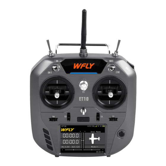
- Page 1 Shezhen WFLY Technology Development Co.,Ld V1.04 ET10 10 Channels Digital Proportional R/C System ET10 Instruction Manual More product information, please follow the WeChat official account above...
- Page 2 Thank you for using WFLY products! ● Please read this product manual carefully before using this product! ● Please use this product properly! The R/C model is not a toy, for safety, please do not fly in crowded places!
- Page 3 Function Catalogue Please read the following instructions carefully before use to ensure safely use of the product Safety Caution Symbols Definition Flying Notices Battery Trainer USB Interface Before Use Product Features Basic Configuration Each Parts Name Of Transmitter Switch Configuration And Types The Travel Of Antenna Direction Adjustment Basic Operation Home Interface Operation...
- Page 4 Function Catalogue System Setting Model Select Save multiple sets of set parameters and switch freely when needed Model Name Name a group of model parameters Model Type Select helicopter,airplane or multicopter Model Copy Copy one group of model parameters to another group of model parameters Model Reset Reset a group of model parameters to initial value Low Voltage...
- Page 5 Function Catalogue Model Menu\Airplane Hold the throttle output status Throttle Hold Adjust the differential of AIL1 and AIL2 AIL Differential Assign another AIL channel Aileron 2 Motion mode assignment Fly Mode To make instant throttle cut after flying Throttle Cut Adjust the linear relation of throttle Throttle Curve Adjust flap end point,change flap channel seperately,control mix will synchronize...
-
Page 6: Safety Caution
Safety Caution Symbols Definition Pay special attention to the safety information of the following symbols WARNING Prohibitions If without a proper operation,it may cause dangerous accident or seriously injury or may even cause death. Compulsory Items DANGER If without a proper operation,it may cause dangerous accident or seriously injury or may even cause death,and it may cause slight hurt or probability cause bodily injure! - Page 7 After flying, turn off the receiver primarily and a crash. When you begin your flying session, reset then turn off the transmitter for protecting people your ET10 built-in timer, and during the session pay from the fail-safe function. attention to the duration of usage.
-
Page 8: Usb Interface
1.Do not attempt to disassemble LiFe packs or machine! cells. The USB interface of the ET10 can be charged. 2.Do not allow LiFe cells to come in contact with Please charge the battery with a USB output charge moisture or water at any time. -
Page 9: Before Use
Basic Configuration Transmitter:ET10 remote controller x1 Receiver:RF209S Receiver x1(External power inspection wire x1) Accessary : Receiver Lanyard x1 Others : Summary manual file x1 Warranty card x1 *WFLY will not notify further if any configuration Lanyard changes. Summary manual x1... - Page 10 Before Use Each Parts Name of Transmitter Antenna Power light RF light SE(3 speed) V1( Rotary knob ) Stick ET10 Hook Trim T3 Trim T2 Trim T1 Trim T4 Power switch Function buttons Navigation button Touch screen Trainer interface USB interface 1 2 3 4 5 6 7 8 6.Power supply...
- Page 11 The antenna activity of the transmitter is limited by the stroke. If the activity is exceeded, the antenna will be damaged. The active travel indication of the antenna is as following: Left and right movement 180° Front and up movement 180° ET10...
-
Page 12: Basic Operation
Basic Operation Home Interface Introduction N O R 8. 4 V ET10 U s e r N a me 00 00 0 00 00 0 Rx :5. 0V E xt : 1 2V M od e l 1 00:06:59 Operation and Introduction 1.Transmitter model... -
Page 13: Touch Screen Operation
Basic Operation Touch Screen Operation ET10 uses 3.5 inches resistance touch screen, which makes ET10 operation more flexible and efficient. 8.4V 8 . 4 V Throttle Hold NORM Throttle Hold NORM NOTICE Status Status Switch Switch Touch the touch screen softly with the stylus pen or your fingertips. -
Page 14: Stick Adjustment
Stick Adjustment Stick head height adjustment Stick feel and function adjustment Tools : 1.5mm socket screwdriver: ET10 uses the newly developed four-bearing Steps: assembly to trim the feel! 1. Loosen the upper section head Uncover the silicone sheet on the back and adjust counterclockwise the feel directly. - Page 15 If you need components such as bracket 5 (such as the parts needed for assembling double circuit structure!), you can e-mail to WFLY overseas seller to order the spare parts at sales@wflysz.com...
-
Page 16: Receiver Instructions
Basic Operation Receiver Instructions Receiver LED STATUS LIST Mode Action State PPM / W.BUS / W.BUS2 Green Never W.BUS normal work mode PWM / PPM / W.BUS Blue Never PWM normal work mode CH1~7 : PWM Work Never No signal Slow flash Low voltage Signal... - Page 17 Basic Operation Receiver and servo Link example - Airplane The figure below shows an example of airplane Link. Please use the actual wing type and tail type for servo Link. AILERON ELEVATOR THROTTLE RUDDER UNDERCARRIAGE FLAP AILERON 2/AUX 1 Servo connection position (Airplane) The table below shows examples of the servo connection positions for the different wing types and tail types.
- Page 18 Basic Operation Receiver and servo Link example -Glider The table below shows examples of the servo link positions for the different wing types and tail types. 1AIL(A-1) 2AIL(A-2) 2A+1F(AF1) 2A+2F(AF2) Aileron Aileron Aileron Aileron Elevator Elevator Elevator Elevator Motor Motor Motor Motor Rudder...
- Page 19 Basic Operation Receiver and servo link example -Helicopter The figure below shows an example of helicopter link. Please use the actual wing type and tail type for servo link. AILERON ELEVATOR THROTTLE RUDDER GYRO PITCH AUX/GOVERNOR Servo link position (Helicopter) The table below shows examples of the servo link positions for different swashes.
- Page 20 Basic Operation Receiver and servo Link example -Multicopter The figure below shows the four-rotor multicopter. Please refer to the model manual for specific applications. Motor,electronic speed controller, flight controller, battery, etc. are sold separately. Use 5CH-9CH when using accessories such as camera shutters.
- Page 21 Models Basic Setting Sequence Basic setting sequence of airplane and glider Taking a conventional F3A as an example, the ● [Dual Rate] adjust The rate adjustment after flight is performed by steps of setting a airplane will be described. In the the [Dual Rate] function.
- Page 22 Models Basic Setting Sequence Basic setting sequence of helicopter Here, a conventional helicopter is taken as an +5 0% RATE + 50% +125 example to explain the setting sequence steps of the +100 helicopter. In the actual setting process, set the appropriate value according to the body to be used.
- Page 23 Models Basic Setting Sequence ●Pitch Curve 6. Setting Idle 2 From the menu, call the [Pitch Curve] interface and Next, set the " Idle 2". select the "Advanced" curve. Idle 2 is mostly used for scrolling. When landing, the maximum pitch is used for both The Idle 2 status is when the Idle switch is in the the high and low positions.
-
Page 24: System Setting
System Setting Model Select Model Name The ET10 can store up to 20 groups of model The model names stored in ET10 can be changed. data, which is used to load the saved model data. The currently selected model name will always be displayed on the standby screen. -
Page 25: Model Type
Also want to save the original settings, please use the [Model Copy] function to back up the model data in advance. Enter the interface: WFLY → System Setting → Model Type Model Type NORM 8.4V... -
Page 26: Model Copy
At the same time, this function can also Enter the interface: WFLY → System Setting→ be used as a function of data backup. Model Reset Notice:... -
Page 27: Low Voltage
WFLY → System Setting → Notice: Sound The ET10 has three voltage detection alarms. In addition to the transmitter voltage, the receiver and Setting method: the receiver's external battery, the two voltage Press the key - press the plus or minus key or the values will only take effect if the "telemetry"... - Page 28 "8 channels", and after a few seconds, the mode detection and switching can be completed. 3 Verification: WFT08/09 toggles the coach switch to position 2 and operates the ET10 related stick or other switch. Check if the servo of the corresponding channel is working normally.
-
Page 29: Back Color
For the operation method, please refer to the model naming. Setting method: Press the key-press the confirmation key to perform the calibration function. According to the yellow point of the operation prompt, perform the ET10 NORM 8 . 4 V User Name NORM 8 . 4 V corresponding stick operation;... - Page 30 Stick Mode Users can choose familiar operating modes Reset all the parameter settings of the transmitter. according to their own operating habits, and ET10 NOTICE offers a choice of 4 operating modes. Note: The switch saves immediately for the stick...
- Page 31 → System Setting→ (Download the upgrade package at Screen Cal en.wflysz.com) Setting method: If you have any questions, please contact WFLY Touch screen-Click the center of the circle after-sales customer service consultation : according to the prompt circle displayed on the service@wflysz.com screen;...
-
Page 32: Screen Lock
System Setting “EXIT”2秒,解锁。 Screen Lock Boot Warning When the transmitter operates the device in the The user sets "Startup warning" according to the actual situation to avoid the cause When the field, the user needs to use the lock screen transmitter is powered on, some functions are function according to the actual needs. -
Page 33: Linkage Setting
→ [Trainer] to set); synchronous action output, that is link successful; 3. There is no other WFLY 2.4GHz system in progress. 4. In the process of linking, if you need to exit the link, click the "Cancel"... - Page 34 Linkage Setting Telemetry The telemetry interface displays the collected Interface path: Method 1: WFLY →Linkage Setting→ Telemetry telemetry data. Method 2:Click the telemetry information box in Note: the standby interface. Inhibiting "Telemetry" when link will affect the use of [Range Check] [Low Battery] [W.BUS Servo] [Telemetry].
-
Page 35: Range Check
(The receiver receives the strength of the Interface path: transmitter signal) and the receiver checks to see if WFLY → Linkage Setting → Range Check the status light and servo are moving smoothly. This comprehensive evaluation of the working distance! 4.2V... - Page 36 F/S state, so that the model can Interface path: WFLY→ Linkage Setting→ Fail Safe make unexpected and dangerous actions to avoid loss and damage. Setting Method: Mode--+/-/confirm key switching program working mode(Switching mode:OFF,F/S,Hold).
-
Page 37: S.bus Servo
The S.BUS servo can memorize its own channel Switching the output mode of receiver and different settings. the servo channel could be PPM/W,BUS(the 8th slot) set through connecting servo on ET10. Notice: PPM mode(RF209S). The 8th slot outputs Notice: a standard 2048 resolution, 8 channel PPM signal. -
Page 38: General Menu
Interface path: WFLY → General Menu→ Monitor When starting the [Sub-Trim] setting, you must firstly sub trim each channel (checked by the monitor) to the center position. - Page 39 General Menu Timer The ET10 has two separate timers available. Timer 模拟器 混控 NORM 8 . 4 V The timer can be used for a variety of timings, Throttle, Status such as the running time of the engine or power...
- Page 40 A and the rate B are both 100% and the switch the EXPA EXPB is -60%. Interface path: WFLY →General Menu→Dual Rate 6 Both the rate A and the rate B are 50% and the EXPA EXPB is 0%. In this case, the servo needs to be...
-
Page 41: End Point
135% Gyrm CH10 Home Interface relative position symbols 0 0: 06 : 5 9 0 0 : 0 6 : 5 9 Trim Step NORM 8.4 V ET10 NORM 8 . 4 V 100% 100% Step Comb Switch Green cursor:... -
Page 42: Program Mix
The mixing rate can be adjusted freely so that the Interface path: WFLY →Model Menu→Program aircraft's wrong tendency can be effectively Mix 1,2,3 corrected. You can set the mixing switch to manually control the activation and deactivation of the mixing. -
Page 43: Model Menu
Interface path: WFLY →Model Menu→Throttle Click on the function name in the upper left corner to Hold exit the interface and save the settings. - Page 44 After the throttle cut function is enabled, the throttle channel 5 or a channel 7. cut or the ESC's fully flameout position can be Enter the interface: WFLY → Model Menu → adjusted. After the function is activated, regardless Aileron 2...
- Page 45 [Aux Channel]. The control switch needs to be set in [Model Menu] → [Fly Mode]. Enter the interface: WFLY → Model Menu→ The curve control switch for throttle hold needs Flap Trim to be set in [Model Menu] → [Throttle Hold].
- Page 46 Enter the interface: WFLY → Model Menu → Connect the right aileron servo to CH1 (aileron) ELE to Flap and the left aileron servo to CH6 (flaps).
- Page 47 When other mixing controls are enabled, the mixing will pop up on the interface. For function conflict prompts, please firstly set other mixed function to be inhibited. Enter the interface: WFLY → Model Menu → Elevon Elevon NO R M 8.4V...
- Page 48 Model Menu Air Brake (Airplane) This function is used for landing or in-flight Enter the interface: WFLY → Model Menu→ Air descent actions. brake ● Generally, the aileron opens upward when used Setting method: as a brake. Press the - arrow keys to select the setting item, ●...
- Page 49 Model Menu Ailvator (Airplane) This function makes the elevator gets the function Interface Path: WFLY →Model Menu→Ailvator of an aileron, and the performance of the aircraft snap roll is improved. The aileron elevator is to Setting method: make the two rudder surfaces on the normal layout...
- Page 50 Click on the function name in the upper left corner to Interface Path: WFLY → Model Menu→ Throttle exit the interface and save the settings. Hold Throttle Hold NORM 8.4 V...
- Page 51 Idle 2 (under gear). in each of the above swash types, the swash rate Enter the interface: WFLY → Model Menu → Fly may not operate correctly. Please adjust the Mode .
- Page 52 (the value throttle, the normal throttle output can be restored! 0 0 : 0 6 : 5 9 on the right indicates the current Enter the interface: WFLY → Model Menu→ throttle stick position.) Throttle Cut Pitch Curve (Helicopter)
-
Page 53: Gyro (Helicopter)
[Gyro]. ● When the idle speed is reduced, the throttle trim switch is used to adjust the amount of Enter the interface: WFLY → Model Menu → descent reduction. Gyro ● The operation switch can be selected from Setting method: the switches SA, SB, SC, and SD. - Page 54 Setting method: 0%, the default value!). Press the - arrow keys to select the setting item, Interface Path:WFLY→Model Menu→Throttle and press the plus or minus key to adjust the value. Hold Click the Back button to exit the interface and save the settings.
- Page 55 Note:When starting the engine, be sure to start position, the functions are only: normal (Gear up) the engine at normal idle speed in normal mode. and stunt 2 (Gear down). Enter the interface: WFLY → Model Menu → Throttle Curve. Interface Path: WFLY →Model Menu→Fly Mode...
- Page 56 ET10 WFLY Shenzhen WFLY Technology Development Co., LTD Address: 3th Floor,C3 Buliding,Xiangli Industry Park,Heping Haoye Road,Fuyog Town,Baoan District,Shenzhen,Guangdong Province,China. Tel:+86-755-29792496 Tel:service@wflysz.com Website:www.wflysz.com WFLY WeChat Official Account...
Need help?
Do you have a question about the ET10 and is the answer not in the manual?
Questions and answers