Table of Contents
Advertisement
Quick Links
Advertisement
Table of Contents

Related Manuals for Danfoss DEVIreg 850


Summary of Contents for Danfoss DEVIreg 850
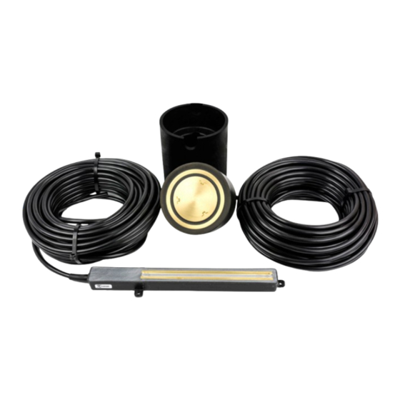
- Page 1 Installation and user manual DEVIreg™ 850 ground and roof sensors www.DEVI.com...
-
Page 2: Table Of Contents
DEVIreg™ 850 ground and roof sensors Table of content Sensors and control zones . . . . . . . . . . . . . . . . . . . . . . . . . . . . . . . . . . . . . . . . . . . . . . . . 3 1.1 Sensor types and function . -
Page 3: Sensors And Control Zones
DEVIreg™ 850 ground and roof sensors Sensors and control zones This section guides you through a short introduction to the terms used in the manual: • Area type • Sensor type • Controller • Control Zones Finally you will be able to assign a number of sensors to the chosen control zones. 1 .1 Sensor types and function Identify the type(s) of area prepared for the DEVI ice and snow melting system, by... -
Page 4: Control Zones
DEVIreg™ 850 ground and roof sensors 1 .2 Control zones A DEVIreg™ 850 and up to 4 sensors are able to control an area as a single zone, but can also control more areas as 2 separated control zones. 2 control zones consits of minimum 2 heating elements + 2-4 sensors and can be: Combi zones when you have both a roof and a ground area Dual zones... -
Page 5: Assign Sensors To Control Zones
DEVIreg™ 850 ground and roof sensors 1 .3 Assign sensors to control zones There are some good reasons to have 2 or more sensors in one control zone. • Higher degree of detection safety, which is relevant for larger, complex or busy roof and ground areas. -
Page 6: Placing And Installation Of Sensors
DEVIreg™ 850 ground and roof sensors Placing and installation of sensors At this point you must have identified and assigned sensors to the control zones as prescribed in section 1. In this section 2 you will be guided through a correct placing and installation of the sensors: •... -
Page 7: Example With Ground Sensors
DEVIreg™ 850 ground and roof sensors 2 .1 .3 Example with ground sensors In this example a lower step section (1), a walkway platform (2) and an upper step section (3) is heated. Depending on number of zones and detection safety, 2-3 ground sensors is installed. -
Page 8: Installing Ground Sensors
DEVIreg™ 850 ground and roof sensors 2 .2 Installing ground sensors At this point you must have located the appropriate spots for the ground sensors and extended the feeder cable if necessary as prescribed in section 2.1. The sensor part and the sensor tube may now be installed in connection with the actual construction work and connected at a later date. - Page 9 DEVIreg™ 850 ground and roof sensors Installation in asphalt: The temperature around the sensor part and sensor tube must not exceed 80°C . A wooden dummy or similar must replace the sensor while asphalt is poured and cooled down . The conduit must be a metal tube that can withstand the high temperatures .
-
Page 10: Placing Roof Sensors
DEVIreg™ 850 ground and roof sensors 2 .3 Placing roof sensors Placing roof sensors in appropriate spots is very important to the performance of the Ice & Snow melting system. The appropriate spot must fulfil some requirements, where the below 2 are the most important: The sensors must be placed minimum 1 m within the boundaries of the heated zone . -
Page 11: Example With Roof Sensors
DEVIreg™ 850 ground and roof sensors 2 .3 .4 Example with roof sensors In this example a roof with several dormers is heated. Depending on the number of zones and required safety it is relevant to install 2-3 roof sensors. Sensor no. -
Page 12: Installing Roof Sensors
DEVIreg™ 850 ground and roof sensors 2 .4 Installing roof sensors At this point you must have selected the appropriate spots for the roof sensors and extended the feeder cable if necessary as prescribed in section 2.3. The roof sensor may now be installed in connection with the actual construction work and connected at a later date. -
Page 13: Technical Specifications
DEVIreg™ 850 ground and roof sensors Technical specifications Technical data Type number: • Ground D850 G1 Sensor • Roof D850 R1 Sensor Voltage: 24VDC +10%/-20% (18-26VDC) Power consumption: • Ground Max. 13W • Roof Max. 8W IP class: IP 67 Ambient temperature: •... -
Page 14: Sensor Cable Extension
DEVIreg™ 850 ground and roof sensors Appendix А 4 .1 Sensor cable extension Ground system Number of sensors: 1 or 2 Cable type Max length (m) Max. length (m) Max length (m) 1 mm2 1.5 mm2 2.5 mm2 4 mm2 1200 Roof system Number of sensors:... -
Page 15: Connections
DEVIreg™ 850 ground and roof sensors 4 .2 Connections Dual zone sensors: Do not join sensor cable extensions from separate zones. Zone A sensor I sensor II Zone B sensor III “Red” “Black” “White” “White” Note each new colour of the 4 wire cable sensor extensions (white, white, red and black) . -
Page 16: Warranty
Danfoss will, at all times, provide a rapid and extra utility expenses. No extension of the warranty effective response to all complaints and inquiries period following repairs undertaken is granted. - Page 17 DEVIreg™ 850 ground and roof sensors Installation and user manual...
- Page 18 DEVIreg™ 850 ground and roof sensors Installation and user manual...
- Page 19 DEVIreg™ 850 ground and roof sensors Installation and user manual...
- Page 20 DEVIreg™ 850 ground and roof sensors Danfoss A/S Nordborgvej 81 6430 Nordborg, Syddanmark Denmark 08095360 & AQ000086456385en-010202 Produced by Danfoss © 06/2023...
Need help?
Do you have a question about the DEVIreg 850 and is the answer not in the manual?
Questions and answers