Table of Contents
Advertisement
Quick Links
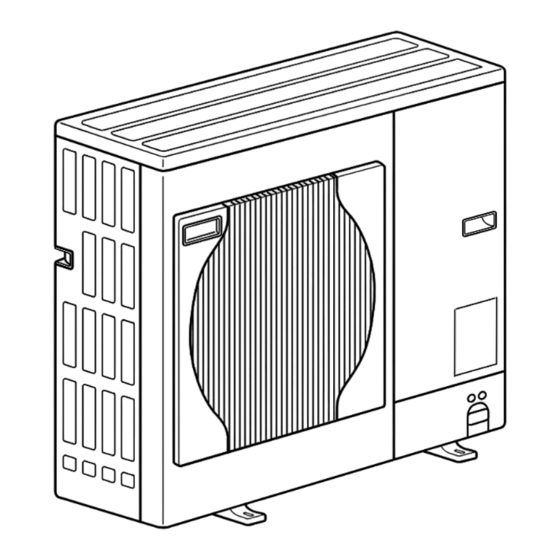
SPLIT-TYPE, AIR TO WATER HEAT PUMP
SERVICE MANUAL
Outdoor unit
[Model names]
PUHZ-SW75VHA
PUHZ-SW100VHA
PUHZ-SW100YHA
PUHZ-SW120VHA
PUHZ-SW120YHA
Salt proof model
PUHZ-SW75VHA-BS
PUHZ-SW100VHA-BS
PUHZ-SW100YHA-BS
PUHZ-SW120VHA-BS
PUHZ-SW120YHA-BS
PUHZ-SW75VHA.UK
PUHZ-SW75VHA-BS.UK
R410A
[Service ref.]
PUHZ-SW75VHA.UK
PUHZ-SW100VHA.UK
PUHZ-SW100YHA.UK
PUHZ-SW100YHAR1.UK
PUHZ-SW120VHA.UK
PUHZ-SW120YHA.UK
PUHZ-SW120YHAR1.UK
PUHZ-SW75VHA-BS.UK
PUHZ-SW100VHA-BS.UK
PUHZ-SW100YHA-BS.UK
PUHZ-SW100YHAR1-BS.UK
PUHZ-SW120VHA-BS.UK
PUHZ-SW120YHA-BS.UK
PUHZ-SW120YHAR1-BS.UK
REVISED EDITION-B
Revision:
• PUHZ-SW100YHAR1(-BS).UK and
PUHZ-SW120YHAR1(-BS).UK
have been added in REVISED
EDITION-B.
• Some descriptions have been
modified.
• Please void OCH533
REVISED EDITION-A.
Note:
• This manual describes only
service data of the outdoor units.
CONTENTS
1. TECHNICAL CHANGES ................................ 2
2. REFERENCE MANUAL ................................. 2
3. SAFETY PRECAUTION ................................. 3
4. FEATURES ..................................................... 7
5. SPECIFICATIONS .......................................... 8
6. DATA ............................................................. 11
7. OUTLINES AND DIMENSIONS ................... 13
8. WIRING DIAGRAM ...................................... 15
9. WIRING SPECIFICATIONS .......................... 19
10. REFRIGERANT SYSTEM DIAGRAM .............. 20
11. TROUBLESHOOTING .................................. 22
12. DISASSEMBLY PROCEDURE ..................... 67
PARTS CATALOG (OCB533)
July 2013
No.OCH533
Advertisement
Table of Contents

Related Manuals for Mitsubishi Electric PUHZ-SW75VHA.UK


Summary of Contents for Mitsubishi Electric PUHZ-SW75VHA.UK
-
Page 1: Table Of Contents
No.OCH533 REVISED EDITION-B SERVICE MANUAL R410A Outdoor unit Revision: • PUHZ-SW100YHAR1(-BS).UK and [Service ref.] [Model names] PUHZ-SW120YHAR1(-BS).UK PUHZ-SW75VHA PUHZ-SW75VHA.UK have been added in REVISED EDITION-B. PUHZ-SW100VHA PUHZ-SW100VHA.UK • Some descriptions have been modified. PUHZ-SW100YHA PUHZ-SW100YHA.UK PUHZ-SW100YHAR1.UK • Please void OCH533 PUHZ-SW120VHA PUHZ-SW120VHA.UK... -
Page 2: Technical Changes
TECHNICAL CHANGES PUHZ-SW100YHA(-BS).UK PUHZ-SW100YHAR1(-BS).UK PUHZ-SW120YHA(-BS).UK PUHZ-SW120YHAR1(-BS).UK • Power circuit board (P.B.) has been changed. REFERENCE MANUAL INDOOR UNIT SERVICE MANUAL Model name Service ref. Service manual No. EHST20C-VM6HB EHST20C-VM6HB.UK EHST20C-YM9HB EHST20C-YM9HB.UK EHST20C-TM9HB EHST20C-TM9HB.UK EHST20C-VM2B EHST20C-VM2B.UK EHST20C-VM6B EHST20C-VM6B.UK EHST20C-YM9B EHST20C-YM9B.UK EHST20C-VM6EB EHST20C-VM6EB.UK EHST20C-YM9EB EHST20C-YM9EB.UK... -
Page 3: Safety Precaution
SAFETY PRECAUTION 3-1. ALWAYS OBSERVE FOR SAFETY Before obtaining access to terminal, all supply circuits must disconnected. Preparation before the repair service. Precautions during the repair service. • Do not perform the work involving the electric parts with wet hands. •... - Page 4 [1] Cautions for service (1) Perform service after recovering the refrigerant left in unit completely. (2) Do not release refrigerant in the air. (3) After completing service, charge the cycle with specified amount of refrigerant. (4) When performing service, install a filter drier simultaneously. Be sure to use a filter drier for new refrigerant.
- Page 5 3-3. PRECAUTIONS WHEN REUSING EXISTING R22 REFRIGERANT PIPES Flowchart • Refer to the fl owchart below to determine if the existing pipes can be used and if it is necessary to use a fi lter dryer. • If the diameter of the existing pipes is different from the specifi ed diameter, refer to technological data materials to confi rm if the pipes can be used. Measure the existing pipe thickness and check for damage.
- Page 6 Cautions for refrigerant piping work New refrigerant R410A is adopted for replacement inverter series. Although the refrigerant piping work for R410A is same as for R22, exclusive tools are necessary so as not to mix with different kind of refrigerant. Furthermore as the working pressure of R410A is 1.6 times higher than that of R22, their sizes of flared sections and flare nuts are different.
-
Page 7: Features
FEATURES PUHZ-SW100VHA.UK PUHZ-SW75VHA.UK PUHZ-SW100YHA.UK PUHZ-SW75VHA-BS.UK PUHZ-SW100YHAR1.UK PUHZ-SW120VHA.UK PUHZ-SW120YHA.UK PUHZ-SW120YHAR1.UK PUHZ-SW100VHA-BS.UK PUHZ-SW100YHA-BS.UK PUHZ-SW100YHAR1-BS.UK PUHZ-SW120VHA-BS.UK PUHZ-SW120YHA-BS.UK PUHZ-SW120YHAR1-BS.UK CHARGELESS SYSTEM PRE-CHARGED REFRIGERANT IS SUPPLIED FOR PIPING LENGTH AT SHIPMENT. (Max. 10m (PUHZ-SW75-120)) The refrigerant circuit with LEV (Linear Expansion Valve) and accumulator always control the optimal refrigerant level regardless of the length (10m max. -
Page 8: Specifications
SPECIFICATIONS <Reference data> Plate heat exchanger (ACH70-40 plates) (SW75) (SW120) Nominal water fl ow L/min 22.9 Nominal water fl ow L/min 45.9 Heating Heating Capacity 16.0 Capacity 8.00 (A7/W35) (A7/W35) 4.40 4.10 Power input 3.90 Power input 1.82 Heating Heating Capacity 8.00 Capacity... - Page 9 PUHZ-SW75VHA.UK Service Ref. PUHZ-SW75VHA-BS.UK Power supply (phase, cycle, voltage) Single, 50Hz, 230V Max. current Munsell 3Y 7.8/1.1 External finish Refrigerant control Linear Expansion Valve Hermetic Compressor TNB220FLHMT Model Motor output Starter type Inverter Protection devices HP switch Comp. surface thermo...
- Page 10 PUHZ-SW100YHA.UK PUHZ-SW120YHA.UK Service Ref. PUHZ-SW120YHAR1.UK PUHZ-SW100YHAR1.UK PUHZ-SW120YHA-BS.UK PUHZ-SW100YHA-BS.UK PUHZ-SW100YHAR1-BS.UK PUHZ-SW120YHAR1-BS.UK Power supply (phase, cycle, voltage) 3 phase, 50Hz, 400V Max. current External finish Munsell 3Y 7.8/1.1 Refrigerant control Linear Expansion Valve Compressor Hermetic Model ANB42FNDMT ANB33FNDMT Motor output Starter type Inverter Protection devices HP switch...
-
Page 11: Data
DATA 6-1. REFILLING REFRIGERANT CHARGE (R410A : kg) Piping length (one way) Initial Service Ref. charged PUHZ-SW75VHA.UK — — — PUHZ-SW75VHA-BS.UK PUHZ-SW100VHA.UK PUHZ-SW100VHA-BS.UK PUHZ-SW100YHA.UK PUHZ-SW100YHAR1.UK PUHZ-SW100YHA-BS.UK PUHZ-SW100YHAR1-BS.UK PUHZ-SW120VHA.UK PUHZ-SW120VHA-BS.UK PUHZ-SW120YHA.UK PUHZ-SW120YHAR1.UK PUHZ-SW120YHA-BS.UK PUHZ-SW120YHAR1-BS.UK Additional charge is required for pipes longer than 10 m. - Page 12 6-3. NOISE CRITERION CURVES PUHZ-SW75VHA.UK SPL(dB) MODE LINE COOLING PUHZ-SW75VHA-BS.UK HEATING MICROPHONE UNIT NC-70 1.5m NC-60 GROUND NC-50 NC-40 NC-30 APPROXIMATE THRESHOLD OF HEARING FOR NC-20 CONTINUOUS NOISE 1000 2000 4000 8000 BAND CENTER FREQUENCIES, Hz PUHZ-SW100VHA.UK PUHZ-SW120VHA.UK PUHZ-SW100VHA-BS.UK PUHZ-SW120VHA-BS.UK PUHZ-SW100YHA.UK...
-
Page 13: Outlines And Dimensions
OUTLINES AND DIMENSIONS PUHZ-SW75VHA.UK Unit : mm PUHZ-SW75VHA-BS.UK OCH533B... - Page 14 PUHZ-SW100VHA.UK PUHZ-SW100VHA-BS.UK Unit : mm PUHZ-SW100YHA.UK PUHZ-SW100YHAR1.UK PUHZ-SW100YHA-BS.UK PUHZ-SW100YHAR1-BS.UK PUHZ-SW120VHA.UK PUHZ-SW120VHA-BS.UK PUHZ-SW120YHA.UK PUHZ-SW120YHAR1.UK PUHZ-SW120YHA-BS.UK PUHZ-SW120YHAR1-BS.UK OCH533B...
-
Page 15: Wiring Diagram
WIRING DIAGRAM PUHZ-SW75VHA.UK PUHZ-SW75VHA-BS.UK SYMBOL NAME SYMBOL NAME SYMBOL NAME Terminal Block <Power Supply, Indoor/Outdoor> P. B. Power Circuit Board Switch <Function Switch, Model Select> Motor for Compressor R, S Connection Terminal <L/N-Phase> Switch <Model Select> Fan Motor U, V, W Connection Terminal <U/V/W-Phase>... - Page 16 PUHZ-SW100VHA.UK PUHZ-SW120VHA.UK PUHZ-SW100VHA-BS.UK PUHZ-SW120VHA-BS.UK SYMBOL NAME SYMBOL NAME SYMBOL NAME Terminal Block <Power Supply, Indoor/Outdoor> P. B. Power Circuit Board Switch <Function Switch> Motor for Compressor U, V, W Connection Terminal <U/V/W-Phase> Switch <Function Switch> MF1, MF2 Fan Motor Connection Terminal <L-Phase> Switch <Function Switch>...
- Page 17 PUHZ-SW100YHA.UK PUHZ-SW120YHA.UK PUHZ-SW100YHA-BS.UK PUHZ-SW120YHA-BS.UK SYMBOL NAME SYMBOL NAME SYMBOL NAME Terminal Block <Power Supply> P. B. Power Circuit Board C. B. Controller Circuit Board Terminal Block <Indoor/Outdoor> TB-U/V/W Connection Terminal <U/V/W-Phase> Switch <Manual Defrost, Defect History, Motor for Compressor TB-L1/L2/L3 Connection Terminal <L1/L2/L3-Power Supply>...
- Page 18 PUHZ-SW100YHAR1.UK PUHZ-SW120YHAR1.UK PUHZ-SW100YHAR1-BS.UK PUHZ-SW120YHAR1-BS.UK SYMBOL NAME SYMBOL NAME SYMBOL NAME Terminal Block <Power Supply> P. B. Power Circuit Board C. B. Controller Circuit Board Terminal Block <Indoor/Outdoor> TB-U/V/W Connection Terminal <U/V/W-Phase> Switch <Manual Defrost, Defect History, Motor for Compressor TB-L1/L2/L3 Record Reset, Refrigerant Address>...
-
Page 19: Wiring Specifications
WIRING SPECIFICATIONS FIELD ELECTRICAL WIRING (power wiring specifications) SW75V SW100V SW120V SW100, 120Y Outdoor unit model ~/N (single), ~/N (single), ~/N (single), 3N~ (3 ph 4-wires), Outdoor unit power supply 50 Hz, 230 V 50 Hz, 230 V 50 Hz, 230 V 50 Hz, 400 V Outdoor unit input capacity Main switch (Breaker) 25 A... -
Page 20: Refrigerant System Diagram
Strainer #100 #100 Detail Symbol Part name COMP Compressor DC inverter twin rotary compressor (Mitsubishi Electric Corporation) H/P SW High pressure switch (63H) For protection (OFF:4.15MPa) L/P SW Low pressure switch (63L) For protection (OFF:-0.03MPa) (SW100/120) REV/V Reversing (4-way) valve (21S4) - Page 21 10-1. REFRIGERANT COLLECTING (PUMP DOWN) When relocating or disposing of the indoor/outdoor unit, pump down the system following the procedure below so that no refriger- ant is released into the atmosphere. 1 Turn off the power supply (circuit breaker). 2 Connect the low-pressure valve on the gauge manifold to the charge plug (lowpressure side) on the outdoor unit. 3 Close the liquid stop valve completely.
-
Page 22: Troubleshooting
TROUBLESHOOTING 11-1. TROUBLESHOOTING <Error code display by self-diagnosis and actions to be taken for service (summary)> Present and past error codes are logged and displayed on the control board of outdoor unit. Actions to be taken for service, which depends on whether or not the trouble is reoccurring at service, are summarized in the table below. Check the contents below before investigating details. - Page 23 11-3. SELF-DIAGNOSIS ACTION TABLE <Abnormalities detected when the power is turned on> Note: Refer to indoor unit section for code P and code E. Abnormal point and detection method Judgment and action Error Code Case 1 No voltage is supplied to terminal 1 Check following items.
- Page 24 Error Code Abnormal point and detection method Case Judgment and action 2 connector open (SW100/120 only) 1 Disconnection or contact failure 1 Check connection of connector (63H,63L) on Abnormal if both 63H and 63L connector of connector (63H,63L) on outdoor controller circuit board. circuits are open for three minutes outdoor controller circuit board.
- Page 25 <Abnormalities detected while unit is operating> Abnormal point and detection method Judgment and action Error Code Case 1 Defective operation of stop 1 Check if stop valve is fully open. High pressure (High-pressure switch 63H operated) valve (Not fully open) 2 Clogged or broken pipe 2 Check piping and repair defect.
- Page 26 Abnormal point and detection method Case Judgment and action Error Code 1 Disconnection or contact failure 1 Check connection of connector (TH3, TH7/6) Open/short of outdoor unit thermistors (TH3, TH6, TH7, and TH8) of connectors on the outdoor controller circuit board. Abnormal if open or short is detected Outdoor controller circuit board: Check connection of connector (CN3) on the...
- Page 27 Abnormal point and detection method Case Judgment and action Error Code To find out the details about U9 error, turn ON SW2-1, 2-2, 2-3, 2-4, 2-5 and 2-6 when U9 error occurs. Detailed To find out the detail history (latest) about U9 error, turn ON SW2-1, 2-2 and 2-6. codes Refer to 11-8.
- Page 28 Abnormal point and detection method Judgment and action Error Code Case 1 Abnormal increase in power 12 Check the field facility for the power PFC error (Overvoltage/ Detailed codes Undervoltage/Overcurrent) source voltage supply. 3 Correct the wiring (U . V . W phase) to 2 Decrease in power source •...
- Page 29 Error Code Abnormal point and detection method Judgment and action Case 1 Stop valve of outdoor unit is 1 Open stop valve. Compressor overcurrent interruption Abnormal if overcurrent DC bus or closed. 2 Decrease of power supply 2 Check facility of power supply. compressor is detected after compressor starts operating for 30 seconds.
- Page 30 Error Code Abnormal point and detection method Judgment and action Case 1 2 remote controller are set as 1 Set a remote controller to main, and the Remote controller transmission error (E3)/ signal receiving error (E5) “main.” other to sub. 1 Abnormal if remote controller could not (In case of 2 remote controllers) find blank of transmission path for 6...
- Page 31 Error Code Abnormal point and detection method Judgment and action Case Freezing/overheating protection is working 1 Overcharge of refrigerant 12 Check operating condition of refrigerant Overheating protection <Heating mode> 2 Defective refrigerant circuit (clogs) circuit. Abnormal if condensing temperature of 3 Malfunction of linear expansion valve pressure sensor (63HS) detects 4 Reduced water flow...
- Page 32 Phenomena Factor Countermeasure 1 After cancelling to select function from the remote 1 Normal operation 3. When pressing the remote controller operation switch, the OPERATION controller, the remote controller operation switch will display is appeared but it will be be not accepted for approx. 30 seconds. turned off soon.
- Page 33 Phenomena Countermeasure A fl owing water sound or occasional hissing sound is heard. ■ These sounds can be heard when refrigerant and/or water is (are) fl owing in the in- door unit or refrigerant pipe, or when the refrigerant and/or water is (are) chugging. ■...
- Page 34 Symptoms: “PLEASE WAIT” is kept being displayed on the remote controller. Inspection method and Diagnosis flow Cause troubleshooting Check the display time of “PLEASE WAIT” after turning on the main power. 6 minutes 2 minutes or more or less How long is “PLEASE WAIT” •...
- Page 35 LED display of the indoor controller board Symptoms: Nothing is displayed on the remote controller LED1 : LED2 : LED3 : Inspection method and Diagnosis flow Cause troubleshooting Check the voltage between S1 and S2 on the terminal block (TB4) of the indoor unit which is used to connect the indoor unit and the outdoor unit.
- Page 36 LED display of the indoor controller board Symptoms: Nothing is displayed on the remote controller LED1 : LED2 : LED3 : Inspection method and Diagnosis flow Cause troubleshooting Check the voltage between S1 and S2 on the terminal block (TB4) of the indoor unit which is used to connect the indoor unit and the outdoor unit.
- Page 37 LED display of the indoor controller board Symptoms: Nothing is displayed on the remote controller LED1 : LED2 : LED3 : — Inspection method and Diagnosis flow Cause troubleshooting Check the voltage of the terminal block (TB6) of the remote controller. DC 10V to DC 16V? •...
- Page 38 • Before repair Frequent calling from customers Phone Calls From Customers How to Respond Note Unit does The operating display of remote Check if power is supplied to air conditioner. not operate controller does not come on. Nothing appears on the display unless power is at all.
- Page 39 Phone Calls From Customers How to Respond Note The room cannot be cooled or heated sufficiently. Check the set temperature of remote controller. The outdoor unit cannot be operated if the set temperature is not appropriate. The outdoor unit operates in the following modes. COOL: When the set temperature is lower than the room temperature.
- Page 40 Phone Calls From Customers How to Respond Note Something Air blows out for a while after However, this control is also This is not a malfunction. is wrong HEAT operation is stopped. The blower is operating just for cooling down the applied to the models which with the heated-up air conditioner.
- Page 41 Phone Calls From Customers How to Respond Note A white mist is expelled from the indoor unit. This is not a malfunction. This may occur when the operation gets started in the room of high humidity. Water or moisture is expelled from the outdoor Cooling;...
- Page 42 Check method of DC fan motor (fan motor/outdoor controller circuit board) Notes · High voltage is applied to the connecter (CNF1, 2) for the fan motor. Pay attention to the service. · Do not pull out the connector (CNF1, 2) for the motor with the power supply on. (It causes trouble of the outdoor controller circuit board and fan motor.) Self check...
- Page 43 <Thermistor feature chart> Low temperature thermistors • Thermistor <Liquid> (TH3) • Thermistor <2-phase pipe> (TH6) • Thermistor <Ambient> (TH7) Thermistor R0 = 15k' ± 3% B constant = 3480 ± 2% =15exp{3480( – 273+t 15k' 4.3k' 9.6k' 3.0k' 6.3k' 5.2k' -20 -10 0 10 20 30 40 50 Temperature ( ) Medium temperature thermistor...
- Page 44 Linear expansion valve (1) Operation summary of the linear expansion valve • Linear expansion valve opens/closes through stepping motor after receiving the pulse signal from the outdoor controller board. • Valve position can be changed in proportion to the number of pulse signal. <Connection between the outdoor controller board and the linear expansion valve>...
- Page 45 (3) How to attach and detach the coil of linear expansion valve <Composition> Linear expansion valve is separable into the main body and the coil as shown in the diagram below. Main body Stopper Coil Lead wire <How to detach the coil> Hold the lower part of the main body (shown as A) firmly so that the main body does not move and detach the coil by pulling it upward.
- Page 46 11-7. TEST POINT DIAGRAM <CAUTION> TEST POINT1 is high voltage. Outdoor controller circuit board PUHZ-SW75VHA(-BS).UK PUHZ-SW100VHA(-BS).UK CNDC DC280V-380V Connect PUHZ-SW120VHA(-BS).UK from outdoor power circuit PUHZ-SW100YHA(-BS).UK board for VHA, connect from noise filter board for (TEST POINT 2) (TEST POINT 1) PUHZ-SW120YHA(-BS).UK (CNDC) (voltage between pins of...
- Page 47 Outdoor noise filter circuit board PUHZ-SW75VHA.UK PUHZ-SW75VHA-BS.UK EI, E2 Connect to the earth LI, NI Voltage of 230V AC is input. (Connect to the terminal block (TB1)) Connect to CNAC1, CNAC2 the earth 230V AC (Connect to the outdoor controller...
- Page 48 Outdoor noise filter circuit board PUHZ-SW100YHA.UK PUHZ-SW100YHA-BS.UK PUHZ-SW120YHA.UK PUHZ-SW120YHA-BS.UK PUHZ-SW100YHAR1.UK PUHZ-SW100YHAR1-BS.UK PUHZ-SW120YHAR1.UK PUHZ-SW120YHAR1-BS.UK LI1, LI2, LI3, NI POWER SUPPLY LI1-LI2/LI-LI3/LI3-LI1 : AC400V input LI1-NI/LI2-NI/LI3-NI : AC230V input (Connect to the terminal block (TB1)) Connect to the earth Connect to the earth CNAC2 AC230V (Connect to the...
- Page 49 Outdoor power circuit board Brief Check of DIP-IPM and DIP-PFC PUHZ-SW75VHA.UK * Usually, they are in a state of being short-circuited if they are broken. Measure the resistance in the following points (connectors, etc.). PUHZ-SW75VHA-BS.UK If they are short-circuited, it means that they are broken.
- Page 50 Outdoor power circuit board Brief Check of POWER MODULE * Usually, they are in a state of being short-circuited if they are broken. PUHZ-SW100VHA.UK Measure the resistance in the following points (connectors, etc.). PUHZ-SW120VHA.UK If they are short-circuited, it means that they are broken. 1.
- Page 51 Outdoor power circuit board Brief Check of POWER MODULE * Usually, they are in a state of being short-circuited if they are broken. PUHZ-SW100YHA.UK Measure the resistance in the following points (connectors, etc.). PUHZ-SW120YHA.UK If they are short-circuited, it means that they are broken. 1.
- Page 52 Outdoor power circuit board Brief Check of POWER MODULE * Usually, they are in a state of being short-circuited if they are broken. PUHZ-SW100YHAR1.UK Measure the resistance in the following points (connectors, etc.). PUHZ-SW120YHAR1.UK If they are short-circuited, it means that they are broken. 1.
- Page 53 Outdoor converter circuit board PUHZ-SW100YHA.UK PUHZ-SW100YHA-BS.UK PUHZ-SW120YHA.UK PUHZ-SW120YHA-BS.UK PUHZ-SW100YHAR1.UK PUHZ-SW100YHAR1-BS.UK PUHZ-SW120YHAR1.UK PUHZ-SW120YHAR1-BS.UK L1-A1 L1-IN, N-IN CK-OU Connect to the ACL1 Connect to the noise filter Connect to the CK capacitor circuit board (LO1, NO) Connect to the outdoor power circuit board (CN7) L1-OU, L2-OU, L3-OU L1-A2, L2-A2, L3-A2...
- Page 54 11-8. FUNCTION OF SWITCHES, CONNECTORS AND JUMPERS (1) Function of switches The black square ( ) indicates a switch position. Action by the switch operation Type of Switch Function Effective timing Switch When compressor is working Forced defrost *1 Start Normal in heating operation.
- Page 55 Note: When PAC-IF011B-E is connected, the use of CN31 is prohibited. (2) Function of connector Action by open/ short operation Types Function Effective timing Connector Short Open Connector CN31 Start When power supply ON Emergency operation Normal Special function (a) Low-level sound priority mode (Local wiring) Unit enters into Low-level sound priority mode by external signal input setting.
- Page 56 <Display function of inspection for outdoor unit> The blinking patterns of both LED1 (green) and LED2 (red) indicate the types of abnormality when it occurs. Types of abnor- mality can be indicated in details by connecting an optional part “A-Control Service Tool (PAC-SK52ST)” to connector CNM on outdoor controller board.
- Page 57 Indication Error Error Outdoor controller board Detailed Contents Inspection method code reference LED1 (Green) LED2 (Red) page 3 blinking 1 blinking Abnormality of comp. surface P.25 Check if stop valves are open. Check if connectors (TH4, TH34, LEV-A, and LEV-B) on outdoor controller thermistor(TH34) and discharging board are not disconnected.
- Page 58 <Outdoor unit operation monitor function> [When optional part ‘A-Control Service Tool (PAC-SK52ST)’ is connected to outdoor controller board (CNM)] Digital indicator LED1 displays 2 digit number or code to inform operation condition and the meaning of error code by controlling DIP SW2 on ‘A-Control Service Tool’. Operation indicator SW2 : Indicator change of self diagnosis SW2 setting...
- Page 59 The black square ( ) indicates a switch position. SW2 setting Display detail Explanation for display Unit Pipe temperature / Liquid (TH3) -40 – 90 -40 – 90 (When the coil thermistor detects 0: or below, “–” and temperature are displayed by turns.) (Example) When -10:;...
- Page 60 The black square ( ) indicates a switch position. SW2 setting Display detail Explanation for display Unit Pipe temperature/Liquid (TH3) on error -40 – 90 occurring (When the coil thermistor detects 0: or below, “–” -40 – 90 and temperature are displayed by turns.) (Example) When –15:;...
- Page 61 The black square ( ) indicates a switch position. SW2 setting Display detail Explanation for display Unit 0 – 3 The number of connected indoor units (The number of connected indoor units are dis- played.) Unit 2 3 4 5 6 Capacity setting display Displayed as an outdoor capacity code.
- Page 62 The black square ( ) indicates a switch position. Display detail Unit SW2 setting Explanation for display Indoor setting temperature 17 – 30 17 – 30 2 3 4 5 6 Pressure saturation temperature (T -39 – 88 63HS -39 – 88 (When the temperature is 0: or less, “–”...
- Page 63 The black square ( ) indicates a switch position. SW2 setting Display detail Explanation for display Unit 180 – 370 (SW75/100/120V) DC bus voltage 300 – 750 (SW100/120Y) 180 – 370 (SW75/100/120V) (When it is 100V or more, hundreds digit, tens 300 –...
- Page 64 The black square ( ) indicates a switch position. SW2 setting Display detail Explanation for display Unit 0 – 480 LEV-A opening pulse on error occurring (When it is 100 pulse or more, hundreds digit, tens 0 – 480 digit and ones digit are displayed by turns.) (Example) When 130 pulse;...
- Page 65 The black square ( ) indicates a switch position. SW2 setting Display detail Explanation for display Unit 0 – 255 Discharge superheat on error occurring (When the temperature is 100°C or more, hundreds digit, tens digit and ones digit are displayed by 0 –...
- Page 66 The black square ( ) indicates a switch position. SW2 setting Display detail Explanation for display Unit Comp. surface temperature (TH34) 3 – 217 3 – 217 (When the comp.shell thermistor detects 100°C or more, hundreds digit, tens digit and ones digit are displayed by turns.) (Example) When 105°C;...
-
Page 67: Disassembly Procedure
DISASSEMBLY PROCEDURE PUHZ-SW75VHA.UK PUHZ-SW75VHA-BS.UK OPERATING PROCEDURE PHOTOS & ILLUSTRATION 1. Removing the service panel and top panel Photo 1 (1) Remove 3 service panel fixing screws (5 × 12) and slide Top panel fixing screws the hook on the right downward to remove the service Top panel panel. - Page 68 OPERATING PROCEDURE PHOTOS 4. Removing the thermistor <2-phase pipe> (TH6) Photo 4 Thermistor (1) Remove the service panel. (See Photo 1) <2-phase pipe> (TH6) Control box (2) Remove the top panel. (See Photo 1) Cable strap (3) Disconnect the connector TH7/6 (red) on the controller circuit board in the control box.
- Page 69 OPERATING PROCEDURE PHOTOS 7. Removing the 4-way valve coil (21S4), LEV coil (LEV-A, Photo 7 LEV-B) 4-way valve coil (1) Remove the service panel. (See Photo 1) 4-way valve fixing screw (2) Remove the top panel. (See Photo 1) LEV coil [Removing the 4-way valve coil] (LEV B) (3) Remove 4-way valve coil fixing screw (M5 ×...
- Page 70 OPERATING PROCEDURE PHOTOS 10. Removing the high pressure switch (63H) Photo 9 Lead wire of (1) Remove the service panel. (See Photo 1) high pressure switch (2) Remove the top panel. (See Photo 1) (3) Remove the control box. (See Photo 3) (4) Remove the valve bed.
- Page 71 OPERATING PROCEDURE PHOTOS 12. Removing the compressor (MC) Photo 11 (1) Remove the service panel. (See Photo 1) (2) Remove the top panel. (See Photo 1) (3) Remove 2 cover panel (front) fixing screws (5 × 12) and remove the front cover panel. (See Photo 2-1) (4) Remove 2 cover panel (rear) fixing screws (5 ×...
- Page 72 PUHZ-SW100VHA.UK PUHZ-SW100VHA-BS.UK PUHZ-SW120VHA.UK PUHZ-SW120VHA-BS.UK OPERATING PROCEDURE PHOTOS & ILLUSTRATION Photo 1 Top panel 1. Removing the service panel and top panel Top panel fixing screws (1) Remove 3 service panel fixing screws (5 × 12) and slide Service panel the hook on the right downward to remove the service fixing screws panel.
- Page 73 OPERATING PROCEDURE PHOTOS 4. Removing the thermistor <2-phase pipe> (TH6) Photo 4 (1) Remove the service panel. (See Photo 1) Thermistor <2-phase pipe> (2) Remove the top panel. (See Photo 1) (TH6) Control box Cable strap (3) Disconnect the connectors, TH7/6 (red), on the controller circuit board in the control box.
- Page 74 OPERATING PROCEDURE PHOTOS Photo 7 7. Removing the 4-way valve coil (21S4), and LEV coil (LEV(A), LEV(B)) 4-way valve coil (1) Remove the service panel. (See Photo 1) (21S4) LEV coil (2) Remove the top panel. (See Photo 1) (LEV A) [Removing the 4-way valve coil] (3) Remove 4-way valve coil fixing screw (M5 ×...
- Page 75 OPERATING PROCEDURE PHOTOS 11. Removing the reactor (DCL) and capacitor (CE) Reactor Control box Photo 9 (1) Remove the service panel. (See Photo 1) (DCL) (2) Remove the top panel. (See Photo 1) (3) Remove the control box. (See Photo 3) <Removing the reactor>...
- Page 76 PUHZ-SW100YHA.UK PUHZ-SW100YHA-BS.UK PUHZ-SW120YHA.UK PUHZ-SW120YHA-BS.UK PUHZ-SW100YHAR1.UK PUHZ-SW100YHAR1-BS.UK PUHZ-SW120YHAR1.UK PUHZ-SW120YHAR1-BS.UK OPERATING PROCEDURE PHOTOS & ILLUSTRATION Photo 1 Top panel 1. Removing the service panel and top panel Top panel fixing screws (1) Remove 3 service panel fixing screws (5 × 12) and slide Service panel the hook on the right downward to remove the service fixing screws...
- Page 77 From the previous page. PHOTOS & ILLUSTRATION OPERATING PROCEDURE (6) Remove the terminal cover and disconnect the compres- Photo 3-2 sor lead wire. Electrical (7) Remove 2 control box fixing screws (4 × 10) and detach parts box the control box by pulling it upward. The control box is fixed with 2 hooks on the left and 1 hook on the right.
- Page 78 PHOTOS OPERATING PROCEDURE Photo 5 5. Removing the thermistor <2-phase pipe> (TH6) Thermistor (1) Remove the service panel. (See Photo 1) <2-phase pipe>(TH6) Control box (2) Remove the top panel. (See Photo 1) (3) Disconnect the connector TH7/6 (red), on the outdoor controller circuit board in the control box.
- Page 79 OPERATING PROCEDURE PHOTOS 8. Removing the 4-way valve coil (21S4), and LEV coil Photo 8 (LEV(A), LEV(B)) 4-way valve coil 4-way valve coil (1) Remove the service panel. (See Photo 1) (21S4) fixing screw (2) Remove the top panel. (See Photo 1) LEV coil (LEV A) [Removing the 4-way valve coil]...
- Page 80 OPERATING PROCEDURE PHOTOS 12. Removing the reactors (ACL1, ACL2, ACL3) Photo 12-1 (1) Remove the service panel. (See Photo 1) (2) Remove the top panel. (See Photo 1) Controller circuit Front panel Screw board (C.B.) (3) Remove the 6 screws, screw (5 ×...
- Page 81 OPERATING PROCEDURE PHOTOS Photo 13 13. Removing the compressor (MC) (1) Remove the service panel. (See Photo 1) (2) Remove the top panel. (See Photo 1) (3) Remove 2 cover panel (front) fixing screws (5 × 12) and remove the cover panel (front). (See Photo 3-1) (4) Remove 2 cover panel (rear) fixing screws (5 ×...
- Page 82 HEAD OFFICE : TOKYO BLDG., 2-7-3, MARUNOUCHI, CHIYODA-KU, TOKYO 100-8310, JAPAN CCopyright 2012 MITSUBISHI ELECTRIC CORPORATION Distributed in Jul. 2013 No.OCH533 REVISED EDITION-B New publication, effective Jul. 2013 Distributed in Oct. 2012 No.OCH533 REVISED EDITION-A Specifications are subject to change without notice.