Table of Contents
Advertisement
SPLIT-TYPE, AIR TO WATER HEAT PUMP
SERVICE MANUAL
Outdoor unit
[Model Name]
PUHZ-SW160YKA
PUHZ-SW200YKA
Salt proof model
PUHZ-SW160YKA-BS
PUHZ-SW200YKA-BS
[Service Ref.]
PUHZ-SW160YKA.UK
PUHZ-SW160YKAR1.UK
PUHZ-SW200YKA.UK
PUHZ-SW200YKAR1.UK
PUHZ-SW160YKA-BS.UK
PUHZ-SW160YKAR1-BS.UK
PUHZ-SW200YKA-BS.UK
PUHZ-SW200YKAR1-BS.UK
R410A
CONTENTS
TECHNICAL CHANGES ······························ 2
1. REFERENCE MANUAL ···························· 2
2. SAFETY PRECAUTION ···························· 2
3. FEATURES ············································ 6
4. SPECIFICATIONS ··································· 7
5. DATA ···················································· 8
6. OUTLINES AND DIMENSIONS ················ 11
7. WIRING DIAGRAM ································ 12
8. WIRING SPECIFICATIONS ····················· 13
9. REFRIGERANT SYSTEM DIAGRAM ··········· 15
10. TROUBLESHOOTING ···························· 17
11. DISASSEMBLY PROCEDURE ················· 60
PARTS CATALOG (OCB583)
August 2015
No. OCH583
REVISED EDITION-A
Revision:
PUHZ-SW160YKAR1.UK,
•
PUHZ-SW160YKAR1-BS.UK,
PUHZ-SW200YKAR1.UK and
PUHZ-SW200YKAR1-BS.UK
in REVISED EDITION-A.
• Some descriptions have been
modified.
• Please void OCH583.
Note:
• This manual describes service
data of the indoor units only.
Advertisement
Table of Contents

Related Manuals for Mitsubishi Electric PUHZ-SW160YKA-BS


Summary of Contents for Mitsubishi Electric PUHZ-SW160YKA-BS
-
Page 1: Table Of Contents
PUHZ-SW200YKA.UK PUHZ-SW200YKA • Please void OCH583. PUHZ-SW200YKAR1.UK Note: • This manual describes service Salt proof model data of the indoor units only. PUHZ-SW160YKA-BS.UK PUHZ-SW160YKA-BS PUHZ-SW160YKAR1-BS.UK PUHZ-SW200YKA-BS.UK PUHZ-SW200YKA-BS PUHZ-SW200YKAR1-BS.UK CONTENTS TECHNICAL CHANGES ······························ 2 1. REFERENCE MANUAL ···························· 2 2. SAFETY PRECAUTION ···························· 2 3. -
Page 2: Technical Changes
TECHNICAL CHANGES Service ref. have been changed as follows. PUHZ-SW160YKA(-BS).UK PUHZ-SW160YKAR1(-BS).UK PUHZ-SW200YKA(-BS).UK PUHZ-SW200YKAR1(-BS).UK 1. A compliance with ErP directive Lot1 has been authorized. REFERENCE MANUAL INDOOR UNIT SERVICE MANUAL Service Model Name Service Ref. Manual No. ERSE-YM9EC.UK ERSE-YM9ECR1.UK ERSE-YM9EC ERSE-MEC.UK ERSE-MEC ERSE-MECR1.UK OCH590... - Page 3 Use a vacuum pump with a reverse flow check Use new refrigerant pipes. valve. In case of using the existing pipes for R22, be careful with Vacuum pump oil may flow back into refrigerant cycle and the following: that can cause deterioration of refrigerant oil, etc. ·...
- Page 4 [3] Service tools Use the below service tools as exclusive tools for R410A refrigerant. Tool name Specifications Gauge manifold · Only for R410A · Use the existing fitting specifications . (UNF1/2) · Use high-tension side pressure of 5.3MPa·G or over. Charge hose ·...
- Page 5 2 Dimensions of flare cutting and flare nut The component molecules in HFC refrigerant are smaller compared to conventional refrigerants. In addition to that, R410A is a refrigerant, which has higher risk of leakage because its working pressure is higher than that of other refriger- ants.
-
Page 6: Features
FEATURES PUHZ-SW160YKA PUHZ-SW200YKA PUHZ-SW160YKA-BS PUHZ-SW200YKA-BS CHARGELESS SYSTEM PRE-CHARGED REFRIGERANT IS SUPPLIED FOR PIPING LENGTH AT SHIPMENT Maximum 30 m The refrigerant circuit with LEV (Linear Expansion Valve) and power receiver/ accumulator always control the optimal refrig- erant level regardless of the length (30 m maximum and 5 m minimum) of piping. The additional refrigerant charging work during installation often causes problems. -
Page 7: Specifications
SPECIFICATIONS PUHZ-SW160YKA(-BS).UK Service Ref. PUHZ-SW200YKA(-BS).UK PUHZ-SW200YKAR1(-BS).UK PUHZ-SW160YKAR1(-BS).UK Power supply (phase, cycle, voltage) 3 phase 50Hz, 400V Max. current Munsell 3Y 7.8/1.1 External finish Linear Expansion Valve Refrigerant control Hermetic Compressor ANB52FRNMT Model Motor output Inverter Starter type Protection devices HP switch Comp. -
Page 8: Data
(kg) 30 m and less 31–40 m and less 41–50 m and less 51–60 m and less 61–70 m and less 71–80 m and less PUHZ-SW160YKA.UK PUHZ-SW160YKA-BS.UK 0.9 kg 1.8 kg 2.7 kg 3.6 kg PUHZ-SW160YKAR1.UK The additional charge PUHZ-SW160YKAR1-BS.UK... - Page 9 5-3. NOISE CRITERION CURVES MICROPHONE UNIT 1.5 m GROUND PUHZ-SW160YKA.UK PUHZ-SW200YKA.UK PUHZ-SW160YKA-BS.UK PUHZ-SW200YKA-BS.UK SPL(dB) SPL(dB) MODE LINE MODE LINE PUHZ-SW160YKAR1.UK PUHZ-SW200YKAR1.UK COOLING COOLING HEATING HEATING PUHZ-SW160YKAR1-BS.UK PUHZ-SW200YKAR1-BS.UK NC-70 NC-70 NC-60 NC-60 NC-50 NC-50 NC-40 NC-40 NC-30 NC-30 APPROXIMATE APPROXIMATE THRESHOLD OF...
- Page 10 5-4. <REFERENCE DATA> PLATE HEAT EXCHANGER (ACH70-74 PLATES) PUHZ-SW200YKA(-BS).UK PUHZ-SW160YKA(-BS).UK PUHZ-SW200YKAR1(-BS).UK PUHZ-SW160YKAR1(-BS).UK Nominal water flow Nominal water flow L/min 63.1 L/min 71.7 Capacity 25.0 Capacity 22.0 Heating Heating (A7/W35) (A7/W35) 4.00 4.20 Power input 6.250 Power input 5.238 Capacity 25.0 Capacity 22.0 Heating...
-
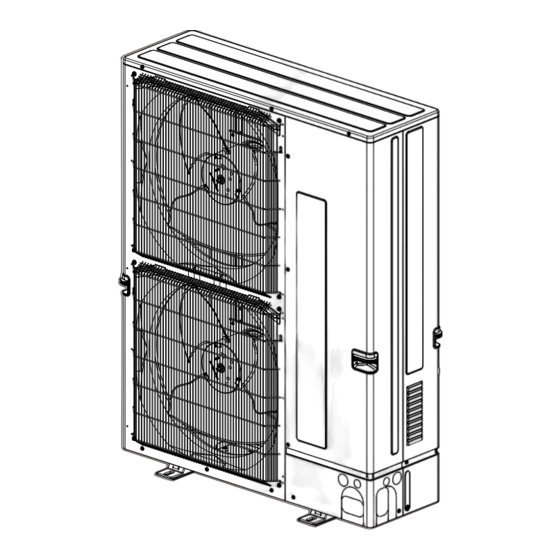
Page 11: Outlines And Dimensions
OUTLINES AND DIMENSIONS PUHZ-SW160YKA.UK PUHZ-SW200YKA.UK PUHZ-SW160YKA-BS.UK PUHZ-SW200YKA-BS.UK Unit: mm PUHZ-SW160YKAR1.UK PUHZ-SW200YKAR1.UK PUHZ-SW160YKAR1-BS.UK PUHZ-SW200YKAR1-BS.UK OCH583A... -
Page 12: Wiring Diagram
WIRING DIAGRAM PUHZ-SW160YKA.UK PUHZ-SW200YKA.UK PUHZ-SW160YKA-BS.UK PUHZ-SW200YKA-BS.UK PUHZ-SW160YKAR1.UK PUHZ-SW200YKAR1.UK PUHZ-SW160YKAR1-BS.UK PUHZ-SW200YKAR1-BS.UK SYMBOL NAME SYMBOL NAME SYMBOL NAME Terminal Block <Power Supply> CY1, CY2 Capacitor Switch <Function Switch> Terminal Block <Indoor/Outdoor> P.B. Power Circuit Board Switch <Function Switch> TB-U/V/W Motor for Compressor Connection Terminal <U/V/W-Phase>... -
Page 13: Wiring Specifications
WIRING SPECIFICATIONS 8-1. FIELD ELECTRICAL WIRING (power wiring specifications) Outdoor unit model SW160/200 Outdoor unit power supply 3N~ (3 ph 4-wires), 50 Hz, 400 V Outdoor unit input capacity main switch (Breaker) *1 32 A Outdoor unit power supply 5 × Min. 4 Cable length 50m: 3×4 (Polar)/ Indoor unit-Outdoor unit Cable length 80m: 3×6 (Polar) - Page 14 8-2. INDOOR – OUTDOOR CONNECTING CABLE The cable shall not be lighter than design 60245 IEC or 60227 IEC. Wire No. o Size (mm²) Outdoor power supply Max. 45 m Max. 50 m Max. 80 m 3 o 1.5 (polar) 3 o 2.5 (polar) 3 o 2.5 (polar) and S3 separated Indoor unit-Outdoor unit...
-
Page 15: Refrigerant System Diagram
REFRIGERANT SYSTEM DIAGRAM 9-1. REFRIGERANT SYSTEM DIAGRAM PUHZ-SW160YKA.UK PUHZ-SW200YKA.UK PUHZ-SW160YKA-BS.UK PUHZ-SW200YKA-BS.UK PUHZ-SW160YKAR1.UK PUHZ-SW200YKAR1.UK PUHZ-SW160YKAR1-BS.UK PUHZ-SW200YKAR1-BS.UK Unit: mm (in) Refrigerant flow in cooling Refrigerant flow in heating High pressure Charge plug sensor 63HS (High pressure) Heat exchanger Ball valve Thermistor TH7... - Page 16 9-2. REFRIGERANT COLLECTING (PUMP DOWN) When relocating or disposing of the indoor/outdoor unit, pump down the system following the procedure below so that no refriger- ant is released into the atmosphere. 1 Turn off the power supply (circuit breaker). 2 Connect the low-pressure valve on the gauge manifold to the charge plug (low pressure side) on the outdoor unit. 3 Close the liquid stop valve completely.
-
Page 17: Troubleshooting
TROUBLESHOOTING 10-1. TROUBLESHOOTING <Check code displayed by self-diagnosis and actions to be taken for service (summary)> Present and past check codes are logged, and they can be displayed on the wired remote controller and control board of out- door unit. Actions to be taken for service, which depends on whether or not the trouble is reoccurring in the field, are summa- rized in the table below. - Page 18 10-2. SELF-DIAGNOSIS ACTION TABLE <Abnormalities detected when the power is put on> Note: Refer to indoor unit section for codes starting with P and E. Abnormal points and detection method Judgment and action Check Code Case 1 No voltage is supplied to termi- 1 Check following items.
- Page 19 Abnormal points and detection method Case Judgment and action Check Code 1 Check disconnection or looseness or polarity 1 Contact failure or miswiring of Miswiring of indoor/outdoor unit indoor/outdoor unit connecting of indoor/outdoor unit connecting wire of connecting wire wire indoor and outdoor units.
- Page 20 <Abnormalities detected while unit is operating> Abnormal points and detection method Judgment and action Check Code Case 1 Decreased water flow 1−5 Check water circuit and repair defect. High pressure (High-pressure switch 2 Clogged filter of water pipe 63H operated) 3 Locked water pump Abnormal if high-pressure switch 63H 4 Malfunction of water pump...
- Page 21 Check Code Abnormal points and detection method Judgment and action Case 1 Check connection of connector (TH3,TH6/TH7) 1 Disconnection or contact failure Open/short of outdoor unit thermistors on the outdoor controller circuit board. Check of connectors (TH3, TH6, TH7, and TH8) connection of connector (CN3) on the outdoor Abnormal if open or short is detected during Outdoor controller circuit...
- Page 22 Abnormal point and detection method Judgment and action Check Code Case To find out the detail history (latest) about U9 error, turn ON SW2-1, 2-2 and 2-6. Detailed Refer to "10-7. FUNCTION OF SWITCHES, CONNECTORS AND JUMPERS". codes 1 Check the field facility for the power supply. 1 Abnormal increase in power source Overvoltage error 2 Correct the wiring (U .
- Page 23 Abnormal point and detection method Judgment and action Check Code Case 1 Defective outdoor fan (fan 1 Check outdoor unit air passage. Over heat protection motor) or short cycle of outdoor Abnormal if thermistor <liquid> (TH3) unit during cooling operation detects 70: or more during compressor 2 Defective thermistor <liquid>...
- Page 24 Check Code Abnormal points and detection method Case Judgment and action 1 Stop valve of outdoor unit is 1 Open stop valve. Compressor overcurrent interruption Abnormal if overcurrent DC bus or com- closed. 2 Check facility of power supply. pressor is detected after compressor starts 2 Decrease of power supply voltage 3 Correct the wiring (U W phase) to...
- Page 25 Check Code Abnormal points and detection method Judgment and action Case Remote controller transmission error 1 2 remote controllers are set as 1 Set a remote controller to main, and the (E3)/signal receiving error (E5) 1 Abnormal if remote controller could not “main.”...
- Page 26 Check Code Case Judgment and action Abnormal points and detection method 1 Indoor/ outdoor unit connecting 1 Check disconnection or looseness of indoor/ Indoor/outdoor unit communication wire has contact failure. outdoor unit connecting wire. error (Transmitting error) (Outdoor unit) 1 Abnormal if “0” receiving is detected 30 2 Defective communication circuit 2–4 Turn the power off, and on again to times continuously though outdoor con-...
- Page 27 10-3. TROUBLESHOOTING OF PROBLEMS Countermeasure Phenomena Factor 1. Remote controller display does not 1 12 V DC is not supplied to remote controller. 1 Check LED2 on indoor controller board. work. (Power supply display is not indicated on LCD.) (1) When LED2 is lit. 2 12–15 V DC is supplied to remote controller, how- Check the remote controller wiring for ever, no display is indicated.
- Page 28 Symptoms: “PLEASE WAIT” is kept being displayed on the remote controller. Inspection method and Diagnosis flow Cause troubleshooting Check the display time of “PLEASE WAIT” after turning on the main power. 6 minutes 2 minutes or more or less How long is “PLEASE WAIT” •...
- Page 29 LED display of the indoor controller board Symptoms: Nothing is displayed on the remote controller. 1 LED1 : LED2 : LED3 : Inspection method and Diagnosis flow Cause troubleshooting Check the voltage between S1 and S2 on the terminal block (TB1) of the indoor unit which is used to connect the indoor unit and the outdoor unit.
- Page 30 LED display of the indoor controller board Symptoms: Nothing is displayed on the remote controller. 2 LED1 : LED2 : LED3 : Inspection method and Diagnosis flow Cause troubleshooting Check the voltage between S1 and S2 on the terminal block (TB1) of the indoor unit which is used to connect the indoor unit and the outdoor unit.
- Page 31 LED display of the indoor controller board Symptoms: Nothing is displayed on the remote controller. 3 LED1 : LED2 : LED3 : — Inspection method and Diagnosis flow Cause troubleshooting Check the voltage of the terminal block of the indoor controller. •...
- Page 32 • Before repair Frequent calling from customers Phone Calls From Customers How To Respond Note 1 The operating display of remote 1 Check if power is supplied to air conditioner. Unit does not operate controller does not come on. Nothing appears on the display unless power is at all.
- Page 33 Phone Calls From Customers How To Respond Note 1 Check the set temperature of remote controller. The room cannot be cooled or heated sufficiently. The outdoor unit cannot be operated if the set temperature is not appropriate. The outdoor unit operates in the following modes. COOL: When the set temperature is lower than the room temperature.
- Page 34 10-4. HOW TO CHECK THE PARTS PUHZ-SW160YKA.UK PUHZ-SW200YKA.UK PUHZ-SW160YKA-BS.UK PUHZ-SW200YKA-BS.UK PUHZ-SW160YKAR1.UK PUHZ-SW200YKAR1.UK PUHZ-SW160YKAR1-BS.UK PUHZ-SW200YKAR1-BS.UK Check points Parts name Thermistor (TH3) Disconnect the connector then measure the resistance with a tester. <Liquid> (At the ambient temperature 10 to 30°C) Thermistor (TH6)
- Page 35 Check method of DC fan motor (fan motor/outdoor controller circuit board) Notes · High voltage is applied to the connecter (CNF1, 2) for the fan motor. Pay attention to the service. · Do not pull out the connector (CNF1, 2) for the motor with the power supply on. board and fan motor.) (It causes trouble of the outdoor controller circuit Self check...
- Page 36 <Thermistor feature chart> Low temperature thermistors • Thermistor <Liquid> (TH3) • Thermistor <2-phase pipe> (TH6) • Thermistor <Ambient> (TH7) Thermistor R0 = 15 k" ± 3% B constant = 3480 ± 2% =15exp{3480( – 273+t 15 k" 4.3 k" 9.6 k" 3.0 k"...
- Page 37 Linear expansion valve (1) Operation summary of the linear expansion valve • Linear expansion valve opens/closes through stepping motor after receiving the pulse signal from the outdoor controller cir- cuit board. • Valve position can be changed in proportion to the number of pulse signal. <Connection between the outdoor controller board and the linear expansion valve>...
- Page 38 (3) How to attach and detach the coil of linear expansion valve <Composition> Linear expansion valve is separable into the main body and the coil as shown in the diagram below. Main body Stopper Coil Lead wire <How to detach the coil> Hold the lower part of the main body (shown as A) firmly so that the main body does not move and detach the coil by pulling it upward.
- Page 39 10-6. TEST POINT DIAGRAM Outdoor controller circuit board PUHZ-SW160YKA.UK PUHZ-SW200YKA.UK PUHZ-SW160YKA-BS.UK PUHZ-SW200YKA-BS.UK PUHZ-SW160YKAR1.UK PUHZ-SW200YKAR1.UK PUHZ-SW160YKAR1-BS.UK PUHZ-SW200YKAR1-BS.UK <CAUTION> TEST POINT1 is high voltage. CNDM Manual defrost, 1 to 2: Input of low-level sound priority mode detect history Demand control setting 1 to 3: Input of external contact point...
- Page 40 Outdoor noise filter circuit board PUHZ-SW160YKA.UK PUHZ-SW200YKA.UK PUHZ-SW160YKA-BS.UK PUHZ-SW200YKA-BS.UK PUHZ-SW160YKAR1.UK PUHZ-SW200YKAR1.UK PUHZ-SW160YKAR1-BS.UK PUHZ-SW200YKAR1-BS.UK LI1, LI2, LI3, NI POWER SUPPLY LI1-LI2/LI-LI3/LI3-LI1 : 400 V AC input LI1-NI/LI2-NI/LI3-NI : 230 V AC input (Connect to the terminal block (TB1)) CNAC1, CNAC2 230 V AC...
- Page 41 2. Check of DIP-IPM P2 - U , P2 - V , P2 - W , N2 - U , N2 - V , N2 - W PUHZ-SW160YKA-BS.UK PUHZ-SW160YKAR1-BS.UK Note: The marks L1 , L2 , L3 , N1 , N2 , P1 , P2 , U , V and W PUHZ-SW200YKA-BS.UK...
- Page 42 10-7. FUNCTION OF SWITCHES, CONNECTORS AND JUMPERS The black square ( ) indicates a switch position. (1) Function of switches Action by the switch operation Type of Default Switch No. Function Effective timing Switch setting When compressor is working Manual defrost * Start Normal in heating operation.
- Page 43 Special function (a) Low-level sound priority mode (Local wiring) By performing the following modification, operation noise of the outdoor unit can be reduced by about 3-4 dB. The low noise mode will be activated when a commercially available timer or the contact input of an ON/OFF switch is added to the CNDM connector (option) on the control board of the outdoor unit.
- Page 44 <Display function of inspection for outdoor unit> The blinking patterns of both LED1 (green) and LED2 (red) indicate the types of abnormality when it occurs. Types of abnormality can be indicated in details by connecting an optional part ‘A-Control Service Tool (PAC-SK52ST)’ to connector CNM on outdoor controller board.
- Page 45 Indication Error Outdoor controller board Check Detailed Contents Inspection method code reference LED1 (Green) LED2 (Red) page 1Check if stop valves are open. 3 blinking 1 blinking Abnormality of comp. surface P.20 2Check if connectors (TH32 and LEV-A) on outdoor controller thermistor(TH32) board are not disconnected.
- Page 46 <Outdoor unit operation monitor function> [When optional part ‘A-Control Service Tool (PAC-SK52ST)’ is connected to outdoor controller board (CNM)] Digital indicator LED1 displays 2 digit number or code to inform operation condition and the meaning of check code by controlling DIP SW2 on ‘A-Control Service Tool’. Operation indicator SW2 : Indicator change of self diagnosis SW2 setting...
- Page 47 The black square ( ) indicates a switch position. Display detail Explanation for display Unit SW2 setting Pipe temperature/Liquid (TH3) −40 to 90 −40 to 90 (When the coil thermistor detects 0: or below, “–” and temperature are displayed by turns.) (Example) When −10:;...
- Page 48 The black square ( ) indicates a switch position. SW2 setting Display detail Explanation for display Unit Pipe temperature/Liquid (TH3) on error −40 to 90 occurring (When the coil thermistor detects 0: or below, “–” −40 to 90 and temperature are displayed by turns.) (Example) When −15:;...
- Page 49 The black square ( ) indicates a switch position. SW2 setting Display detail Explanation for display Unit 0 to 4 The number of connected indoor units (The number of connected indoor units are dis- played.) Unit 2 3 4 5 6 Capacity setting display Displayed as an outdoor capacity code.
- Page 50 The black square ( ) indicates a switch position. SW2 setting Display detail Explanation for display Unit Indoor setting temperature 17 to 30 17 to 30 °C 2 3 4 5 6 Outdoor pipe temperature/2-phase −39 to 88 (TH6) (When the temperature is 0: or less, “–” and °C −39 to 88 temperature are displayed by turns.)
- Page 51 The black square ( ) indicates a switch position. SW2 setting Display detail Explanation for display Unit Error postponement code history (2) Postponement code display of outdoor unit Blinking: During postponement Code Lighting: Cancellation of postponement display “00” is displayed in case of no postponement. 2 3 4 5 6 Error postponement code history (3) Postponement code display...
- Page 52 The black square ( ) indicates a switch position. SW2 setting Display detail Explanation for display Unit Outdoor temperature/Ambient (TH7) on −39 to 88 error occurring (When the temperature is 0°C or less, “–” and −39 to 88 temperature are displayed by turns.) (Example) When −15°C;...
- Page 53 The black square ( ) indicates a switch position. Display detail Unit SW2 setting Explanation for display Controlling status of compressor The following code will be a help to know the operating frequency operating status of unit. • The tens digit Display Compressor operating frequency control Primary current control Secondary current control...
- Page 54 10-8. Request code list Certain indoor/outdoor combinations do not have the request code function; therefore, no request codes are displayed. Refer to indoor unit service manual for how to use the controllers and request codes for indoor unit. Description Request content Unit Remarks (Display range)
- Page 55 Description Request content Unit Remarks (Display range) – Outdoor unit-Control state – Refer to 10-8-1.Detail Contents in Request Code. Refer to 10-8-1.Detail Contents in Request Code. Compressor-Frequency control state – Outdoor unit-Fan control state Refer to 10-8-1.Detail Contents in Request Code. –...
- Page 56 Description Request content Unit Remarks (Display range) Error history 1 (latest) Displays error history. (" --" is displayed if no history is present.) Code Error history 2 (second to last) Displays error history. (" --" is displayed if no history is present.) Code Error history 3 (third to last) Displays error history.
- Page 57 10-8-1. Detail Contents in Request Code [Operation state] (Request code :" 0") Relay output state Power currently Data display Display Compressor 4-way valve Solenoid valve supplied to compressor – – – – Relay output state Operation mode Operation mode Display Operation mode STOP •...
- Page 58 [Actuator output state] (Request code :"54") Data display Actuator output state 1 Actuator output state 2 Actuator output state Actuator output state Compressor is Display 4-way valve Compressor Display warming up [Error content (U9)] (Request code :"55 ") Data display Error content 1 Error content 2 Error content...
- Page 59 [Outdoor unit – Setting information] (Request code : "71") Setting information 1 Data display Display Defrost mode Setting information 1 Standard Setting information 2 For high humidity Setting information 2 Single-/ Heat pump/ Display 3-phase cooling only Heat pump Single-phase Cooling only Heat pump 3-phase...
-
Page 60: Disassembly Procedure
DISASSEMBLY PROCEDURE PUHZ-SW160YKA.UK PUHZ-SW200YKA.UK PUHZ-SW160YKA-BS.UK PUHZ-SW200YKA-BS.UK PUHZ-SW160YKAR1.UK PUHZ-SW200YKAR1.UK PUHZ-SW160YKAR1-BS.UK PUHZ-SW200YKAR1-BS.UK OPERATING PROCEDURE PHOTOS Photo 1 1. Removing the service panel and top panel (1) Remove the service panel fixing screws (4 for front/ 5 x 12), then slide the service panel downward to remove it. - Page 61 OPERATING PROCEDURE PHOTOS 3. Removing the electrical parts box Photo 4 Electrical parts box (1) Remove the service panel. (See Photo 1) (2) Remove the top panel. (See Photo 1) (3) Disconnect the power supply cable from terminal block. (4) Disconnect the indoor/outdoor connecting wire from Controller terminal block.
- Page 62 PHOTOS OPERATING PROCEDURE Controller 4. Disassembling the electrical parts box Cont base circuit board (C.B.) Photo 5 (1) Disconnect all the connectors on the controller circuit board. (2) To remove the controller circuit board, release it from the support. (3) Remove cont base fixing screws (2 for front/ 4 x 10). (Photo 5) (The cont.
- Page 63 OPERATING PROCEDURE PHOTOS 6. Removing the thermistor <Ambient> (TH7) Photo 11 (1) Remove the service panel. (See Photo 1) (2) Remove the top panel. (See Photo 1) (3) Disconnect the connector TH7/6 (RED) on the controller circuit board in the electrical parts box. (See Photo 4) (4) Loosen the fastener for the lead wire in the electrical parts box.
- Page 64 OPERATING PROCEDURE PHOTOS 8. Removing the 4-way valve coil (21S4), LEV coil (LEV (A)) Photo 13 and lead wire for high pressure switch. High pressure (1) Remove the service panel. (See Photo 1) switch (2) Remove the top panel. (See Photo 1) (3) Remove the electrical parts box.
- Page 65 OPERATING PROCEDURE PHOTOS 10. Removing the compressor (MC) Photo 14 (1) Remove the service panel. (See Photo 1) (2) Remove the top panel. (See Photo 1) (3) Remove the electrical parts box. (See Photo 4) Valve bed (4) Remove the cover panel (front). (See Photo1) (5) Remove the cover panel (rear).
- Page 66 HEAD OFFICE : TOKYO BLDG., 2-7-3, MARUNOUCHI, CHIYODA-KU, TOKYO 100-8310, JAPAN CCopyright 2015 MITSUBISHI ELECTRIC CORPORATION New publication, effective Aug. 2015 Distributed in Aug. 2015 No. OCH583 REVISED EDITION-A Specifications are subject to change without notice. Distributed in Mar. 2015 No. OCH583...