
Related Manuals for Samsung AC100RN4PKG


Summary of Contents for Samsung AC100RN4PKG
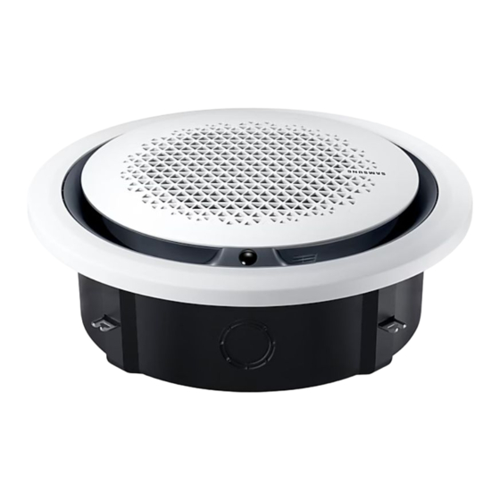
- Page 1 Air conditioner Installation manual AC***RN4PKG Thank you for purchasing this Samsung air conditioner. Before operating this unit, please read this manual carefully and retain it for future reference.
-
Page 2: Table Of Contents
Contents Safety Information Safety Information Installation Procedure Step 1 Checking and preparing accessories Step 2 Choosing the installation location Step 3 Optional: Insulating the body of the indoor unit Step 4 Installing the indoor unit Step 5 Purging inert gas from the indoor unit Step 6 Cutting and flaring the pipes Step 7 Connecting the assembly pipes to the refrigerant pipes Step 8 Performing the gas leak test... -
Page 3: Safety Information
WARNING This manual explains how to install an indoor unit with a split system with two SAMSUNG units. The use of other IMPORTANT: When installing the unit, always remember to types of units with different control systems may damage connect first the refrigerant tubes, then the electrical lines. - Page 4 Safety Information Do not install the product in a place where thermohygrostat Verify that the voltage and frequency of the power supply is needed (such as server room, machinery room, computer comply with the specifications and that the installed power room, etc.) Those places do not provide guaranteed operation is sufficient to ensure the operation of any other domestic condition of the product therefore performance can be poor...
-
Page 5: Installation Procedure
Installation Procedure Step 1 Checking and preparing WARNING accessories Because your air conditioner contains R-32 refrigerant, make sure that it is installed, operated, The following accessories are supplied with the indoor and stored it in a room whose floor area is larger unit. - Page 6 Wire insert hole Large+, Large: 180, Small: 150 Large+, Large: 152, Small: 122 ø100 Common Square panel Circular panel Model AC071RN4PKG AC100RN4PKG AC120RN4PKG AC140RN4PKG Chassis Small Large Large+ Net dimension (W × D × H) mm 947 x 947 x 281...
- Page 7 Refrigerant 1500 mm or pipe more Obstruction Indoor unit display (Unit: mm) Model AC071RN4PKG AC100RN4PKG AC120RN4PKG AC140RN4PKG Connection part of the ø1010 to 1020 drain hose Ceiling opening diameter Inspection hole ø1010 to 1020 CAUTION Comply with the length and height limits described in the NOTE figure above.
-
Page 8: Step 3 Optional: Insulating The Body Of The Indoor Unit
(Unit: mm) Indoor unit type and models Dimensions 360 cassette type <S> AC071RN4PKG 2610 x 130 (947 x 947 x 281) AC100RN4PKG 360 cassette type <L> 2610 x 215 (947 x 947 x 365) AC120RN4PKG 360 cassette type <L+> AC140RN4PKG... - Page 9 2 Perform the following steps to install inspection holes 4 Install the suspension bolts, depending on the ceiling in accordance with the panel type. type. a For the recessed installation of the square panel. Install an inspection hole to the direction of Ceiling support connection parts of the refrigerant pipe and the drain hose.
-
Page 10: Step 5 Purging Inert Gas From The Indoor Unit
Installation Procedure 7 Adjust the unit to the appropriate position, taking into Step 6 Cutting and flaring the pipes account the installation area for the front panel. 1 Make sure that you have the required tools available: Place the pattern sheet on the indoor unit. pipe cutter, reamer, flaring tool, and pipe holder. -
Page 11: Step 7 Connecting The Assembly Pipes To The Refrigerant Pipes
5 Check that the flaring is correct, referring to the Outer Diameter (mm) illustrations below for examples of incorrect flaring. Ø6.35 14 to 18 Ø9.52 34 to 42 Ø12.70 49 to 61 Ø15.88 68 to 82 Ø19.05 100 to 120 NOTE Cracked Uneven... -
Page 12: Step 8 Performing The Gas Leak Test
Installation Procedure Step 8 Performing the gas leak test CAUTION To identify potential gas leaks on the indoor unit, inspect Be sure to wrap insulation tightly without any gaps. the connection area of each refrigerant pipe using a leak detector for R-410A. 3 Finish wrapping insulating tape around the rest of the pipes leading to the outdoor unit. -
Page 13: Step 10 Installing The Drain Hose And Drain Pipe
Step 10 Installing the drain hose and Insulation type (heating/cooling) drain pipe Standard Pipe size High humidity Pipe Remarks (Less than 30°C, 1 Push the supplied drain hose as far as possible over (mm) (Over 30°C, 85%) 85%) the drain socket. EPDM, NBR (mm) 2 Tighten the metal clamp as shown in the picture. - Page 14 Installation Procedure Do not apply force to the piping on the unit side CAUTION when connecting the drain hose. The hose should not Check that the indoor unit is level with the ceiling by be allowed to hang loose from its connection to the using the leveller.
-
Page 15: Step 11 Performing The Drainage Test
Max. allowable bending angle. c Check the leak test at the part where the adhesive for the flexible hose and the drain pipe is used. CAUTION The leak test must be performed for at least 24 hours. Indoor unit 2 Check the condensed water drainage: a Pour about 2 liters of water into the indoor unit drain pan as shown in the picture. -
Page 16: Step 12 Optional: For The Installation Of The Circular Panel
Installation Procedure 2 Put a pencil at the opposite side of the pivot point CAUTION fixed in place. When the float switch is not detected due to insufficient water on the drain pan, the drain pump will not work. If the power supply is directly connected to the L and N terminals, communication error message might appear. -
Page 17: Step 13 Optional: Installing Dpm (Digital Packaged Multi)
Step 13 Optional: Installing DPM The indoor unit is powered through the outdoor unit by means of a H07 RN-F connection cable (or a more power (Digital Packaged Multi) model), with insulation in synthetic rubber and a jacket in polychloroprene (neoprene), in accordance with the NOTE requirements specified in the standard EN 60335-2-40. - Page 18 Installation Procedure Wiring terminals) 3 phase Indoor power supply Power supply Max/Min(V) Indoor power cable ±10% 220 to 240V, 50 Hz 0.75 mm² , 3 wires Indoor unit Communication cable 0.75 mm², 2 wires Outdoor unit (Unit: mm) 1(L) 2(N) L1(R) L2(S) L3(T)
-
Page 19: Step 15 Optional: Extending The Power Cable
Step 15 Optional: Extending the 3 Insert both sides of core wire of the power cable into the connection sleeve. power cable Method 1: Push the core wire into the sleeve from 1 Prepare the following tools. both sides. Method 2: Twist the wire cores together and push Tools Spec Shape... -
Page 20: Step 16 Setting The Indoor Unit Addresses And The Installation Options
Installation Procedure 5 Apply heat to the contraction tube to contract it. Step 16 Setting the indoor unit addresses and the installation options Method 1 Method 2 You cannot set both of the indoor unit addresses and Contraction tube Contraction tube the installation options in a batch: set both of them respectively. - Page 21 2 Set the option values. SEG1 SEG2 SEG3 SEG4 SEG5 SEG6 CAUTION SEG7 SEG8 SEG9 SEG10 SEG11 SEG12 The total number of available options are 24: SEG1 to SEG24. Because SEG1, SEG7, SEG13, and SEG19 are the page SEG13 SEG14 SEG15 SEG16 SEG17...
- Page 22 Installation Procedure Steps Remote control display b Set the SEG5 value by rotating the Wheel clockwise until the value you want to set appears on the remote control display. SEG5 When you rotate the Wheel, values appear in the following order: 4 Press the (Mode) button.
- Page 23 Steps Remote control display 9 Set the SEG11 and SEG12 values: a Set the SEG11 value by rotating the Wheel counterclockwise until the value you want to set appears on the remote control display. SEG11 b Set the SEG12 value by rotating the Wheel clockwise until the value you want to set appears on the remote control display.
- Page 24 Installation Procedure Steps Remote control display 14 Press the (Mode) button. Dry and Off appear on the remote control display. 15 Set the SEG18 and SEG20 values: a Set the SEG18 value by rotating the Wheel counterclockwise until the value you want to set appears on the remote control display.
- Page 25 Steps Remote control display b Set the SEG24 value by rotating the Wheel clockwise until the value you want to set appears on the remote control display. SEG24 When you rotate the Wheel, values appear in the following order: 3 Check whether the option values that you have set are Remote controls correct by pressing the (Mode) button repeatedly...
- Page 26 Installation Procedure 2 Set the option values. SEG1 SEG2 SEG3 SEG4 SEG5 SEG6 CAUTION SEG7 SEG8 SEG9 SEG10 SEG11 SEG12 The total number of available options are 24: SEG1 to SEG24. Because SEG1, SEG7, SEG13, and SEG19 are the page SEG13 SEG14 SEG15...
- Page 27 Steps Remote control display 3 Set the SEG4 and SEG5 values: a Set the SEG4 value by pressing the (Low Fan) button repeatedly until the value you want to set appears on the remote control display. SEG4 b Set the SEG5 value by pressing the (High Fan) button repeatedly until the value you want to set appears on the remote control display.
- Page 28 Installation Procedure Steps Remote control display b Set the SEG10 value by pressing the (High Fan) button repeatedly until the value you want to set appears on the remote control display. SEG10 When you press the (Low Fan) or (High Fan) button, values appear in the following order: 8 Press the (Mode) button.
- Page 29 Steps Remote control display 12 Press the (Mode) button. Cool and Off appear on the remote control display. 13 Set the SEG16 and SEG17 values: a Set the SEG16 value by pressing the (Low Fan) button repeatedly until the value you want to set appears on the remote control display. SEG16 b Set the SEG17 value by pressing the (High Fan) button repeatedly until the...
- Page 30 Installation Procedure Steps Remote control display b Set the SEG22 value by pressing the (High Fan) button repeatedly until the value you want to set appears on the remote control display. SEG22 When you press the (Low Fan) or (High Fan) button, values appear in the following order: 18 Press the (Mode) button.
- Page 31 Setting the indoor unit addresses 2 Set an address for each indoor unit using the remote control, according to your air conditioning system plan, by referring to the following table and by Option No. for an indoor unit address: following the steps in Common steps for setting the 0AXXXX-1XXXXX-2XXXXX-3XXXXX addresses and options on page 20.
- Page 32 Installation Procedure 1 Make sure that the power is supplied to the indoor CAUTION unit. If the indoor unit is not plugged in, it must include a power supply. The main address must be set to a value in the range 0 to 15.
- Page 33 Option SEG13 SEG14 SEG15 SEG16 SEG17 SEG18 Setting the output Maximum filter Function Page Use of external control S-Plasma ion Buzzer control of external control usage time Indication Details Indication Details Indication Details Indication Details Indication Details Indication Details Disuse Slave, On/Off Existing...
- Page 34 Installation Procedure Even if you set the Use of drain pump (SEG8) option to 0, it is automatically set to 2 (the drain pump is used with 3 minute delay). Example: When installing DPM (1 Outdoor unit with 4 indoor units) Condition SEG14 Setting Result...
- Page 35 Emergency Temperature Output (ETO) function CAUTION In order to deploy the ETO function, the MIM-B14, an external contact interface module, must be installed in each indoor unit. – The ETO is a concept of emergency operation of indoor units. If the indoor unit 1 (main indoor unit) stops because of an error, the indoor unit 2 (sub indoor unit) starts to operate.
- Page 36 Installation Procedure ETO operation specifications 1 Main indoor unit – Based on the external contact control settings, the main indoor unit decides whether to generate output when an error (indoor unit stop) occurs. – Based on the ETO settings, the main indoor unit decides whether to generate output according to the temperature and time conditions.
-
Page 37: Appendix
Troubleshooting Indoor unit display indications Condition Ice blue Yellow green Blue Power reset (blinking once every 2 seconds) In the defrost operation (blinking once every 10 seconds) Open or short circuit error of the indoor-temperature sensor Error of the outdoor unit Communication error between the indoor and outdoor units Open or short circuit error of a sensor (evaporator-in, evaporator-out, or discharge sensor) in the indoor unit... - Page 38 This appliance is filled with R-32.