Table of Contents
Advertisement
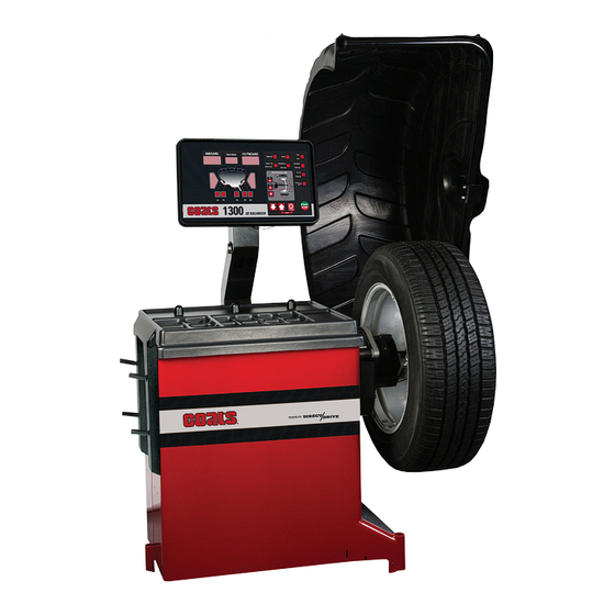
Model 1300-2D
Wheel Balancer
See
Balancing Your
First Tire
on page 4.
1601 J. P . Hennessy Drive, LaVergne, TN USA 37086
HENNESSY INDUSTRIES LLC. Manufacturer of COATS
Safety Instructions
Set-up Instructions
Operation Instructions
Maintenance Instructions
READ these instructions before placing unit in
service. KEEP these and other materials delivered
with the unit in a binder near the machine for ease
of reference by supervisors and operators.
615/641-7533
800/688/6359
www.coatsgarage.com
, AMMCO
and BADA
Automotive Service Equipment and Tools.
®
®
®
Manual Part No.: 85610936 02
Revision:
2/20
Advertisement
Chapters
Table of Contents

Related Manuals for HENNESSY INDUSTRIES coats 1300-2D


Summary of Contents for HENNESSY INDUSTRIES coats 1300-2D
- Page 1 1601 J. P . Hennessy Drive, LaVergne, TN USA 37086 615/641-7533 800/688/6359 www.coatsgarage.com Manual Part No.: 85610936 02 HENNESSY INDUSTRIES LLC. Manufacturer of COATS , AMMCO and BADA Automotive Service Equipment and Tools. Revision: 2/20 ®...
- Page 2 IMPORTANT SAFETY INSTRUCTIONS READ ALL INSTRUCTIONS Eye and face protection recommendations: 10. Wear proper clothing. Safety toe, non-slip foot- wear and protective hair covering to contain hair “Protective eye and face equipment is required to is recommended. Do not wear jewelry, loose be used where there is a reasonable probability clothing, neckties, or gloves when operating the of injury that can be prevented by the use of such...
-
Page 3: Operator Protective Equipment
Owner’s Responsibility Definitions of Hazard Levels To maintain machine and user safety, the responsibil- Identify the hazard levels used in this manual with the ity of the owner is to read and follow these instructions: following definitions and signal words: DANGER •... -
Page 4: Safety Notices And Decals
• A hood guard of high impact plastic that is designed contact: to prevent the counterweights from flying out in any direction except towards the floor. Hennessy Industries LLC 1601 JP Hennessy Drive • A hood switch interlock system that prevents the LaVergne, TN 37086... -
Page 5: Table Of Contents
Table of Contents Owner’s Responsibility ........... iii Direct Select™ Weight Location ......12 Operator Protective Equipment ......iii Setting Wheel Dimensions (DIM) ......12 Definitions of Hazard Levels ........iii Definition of Dimensions (DIM) ......12 Safety Notices and Decals ........iv Basic Wheel Data Entry ........ -
Page 6: Set Up Instructions
Set Up Instructions Machine Set Up Receiving The shipment should be thoroughly inspected as soon as it is received. The signed bill of lading is acknowl- Do not use the control panel, control panel edgement, for the carrier, of receipt in good condition base, accessory storage, faceplate, hood or of the shipment covered by our invoice. -
Page 7: Specifications
Specifications Features Wheel Diameter Range • Automatic Data Entry for Offset and Diameter - 8 - 30 inches (203 - 762 mm) Manual Entry Backup on all Parameters. Wheel Width Range • Static-on-Screen™ 2 - 20 inches (51 - 508 mm) •... -
Page 8: Balancing Your First Tire
★Balancing Your First Tire 1. Turn the machine OFF then ON Raise hood after tire stops rotating. (resets machine). The machine wakes up using Note: Wait for wheel to stop before raising standard clip-on wheel weight the wheel guard. locations (Clip 1 & Clip 2) and Rotate wheel until Inboard wheel dimensions. -
Page 9: Principle Operating Parts
Principle Operating Parts - Control Panel Know Your Unit - ON/OFF Switch (back of machine) Compare this illustration with the unit before placing - Plug (back of machine) it into service. Maximum performance and safety will be obtained only when all persons using the unit are - Weight Tray with Pockets for Weights fully trained in its parts and operation. -
Page 10: Power Switch
Note: Throughout this manual, wheel weights are Using The Offset Arm referred to as Clip-on or Tape-A-Weight®. Figure 4 When not in use or when prompted by the balancer shows an example of each weight. instructions, store the offset arm in the home position as shown in figure 6. - Page 11 Be sure to place the offset arm on the wheel flange at Important: The A2 measurement must be at least 2 the clip-on weight location as shown, figure 8. inches greater than the A1 measurement. At least 2-inch minimum difference Figure 8 - Clip-on Weight Location Viewed on a Cut-Away Rim for Clarification Note: Use the offset arm to automatically measure...
-
Page 12: Control Panel Layout
Control Panel Layout Figure 12 - Control Panel Feature Reference Control Panel Function and Review Weight Display Windows Two weight display windows, one Inboard and one Outboard, are positioned above the Wheel Cross-section Diagram. After a wheel measurement cycle, the balancer calculates the corrective weight amount and indicates it in the appropriate display window. - Page 13 Key Group If you press/select ... Then indicator illuminates/displays... Balance Mode Keys that Match Balance (Optimization) Match mode is activated. that Behind Spoke mode is activated Spoke Toggle to activate / select location 1 or location 2 for adhesive weights. that Machine Calibration mode is Calibration activated.
-
Page 14: Mounting Wheel On Balancer Shaft
Mounting Wheel On Balancer Standard Back Cone Mounting Standard Back Cone/Collet Mounting Shaft Most original equipment and steel wheels can be mounted properly using this method. The wheel is centered on a cone from the inner side of the hub. Avoid back injury, seek assistance when lifting heavy tire/rim assemblies onto the balancer shaft. -
Page 15: Standard Front Cone Mounting
Alternate Mounting Optional Front Cone/Collet Mounting Alternate Mounting Front Cone/Collet Mounting A wheel should be centered by the outer side of the If the wheel has a protruding outer hub which will not hub only when the inner surface will not provide an permit the use of the pressure cup, or the cup will not accurate surface to center on. -
Page 16: Direct Select™ Weight Location
Direct Select™ Weight Location Setting Wheel Dimensions (DIM) Before spinning the wheel, use direct select to indicate Before a wheel can be balanced, wheel dimensions weight placement locations on the wheel as follows: must be entered into the computer. Definition of Dimensions (DIM) A = Offset The distance measured from the balancer (“0”... -
Page 17: Basic Wheel Data Entry
Basic Wheel Data Entry Entering Wheel Dimensions Manually 1. Direct Select™ an Inboard weight location (Clip 1, Information entered into the balancer software for A, or T1 Tape) and an Outboard weight location (T2 Tape, W, and D can be changed anytime during a balancing T3 Tape or Clip 2). -
Page 18: Balancing A Wheel
Balancing A Wheel Static Balancing Choose a static balance to balance a wheel using one A variety of wheel configurations can be balanced plane for correction. Place the single corrective weight using this wheel balancer. Read through this section, at top-dead-center (12 o’clock) on either flange, at the it will help in determining which balancing mode and center of the rim channel, placed inward either side, or options are best suited for certain wheel assemblies. -
Page 19: Behind Spoke Mode
Corrective Weight Placement Behind Spoke Mode “Splitting” the T2 Tape corrective weight amount After the wheel spins and out of balances are mea- is used to hide the adhesive weight behind two rim sured and displayed, the corrective weight amount spokes. -
Page 20: Match Balance (Optimization)
Match Balance (Optimization) Match Balance Mode If you choose to use Match Balance to correct for a condition, such as a large static unbalance, then follow the machine prompts and instructions for the MATCH BALANCE procedure as outlined in the following steps. Match Balance involves the loosening of Note: Use this procedure only after the wheel has tire beads and the inflation of a tire. -
Page 21: Calibration Program
Calibration Program Important: It is critical that the inner weight be placed accurately to achieve proper calibration. If the Important: Be sure to use the correct calibration calibration weight is not moved from the outside flange weight amount: a 4-ounce calibration weight with the directly across to the inside flange, an inner weight ounce option or a 100-gram calibration weight with the placement error will occur and the calibration will be... -
Page 22: Arm Calibration
Arm Calibration 8. Return arm to home position. Important: Always perform the Arm Calibration 9. When machine displays “END”, the Arm Calibra- immediately after Machine Calibration. The balancer tion is complete. Press FUNCTION to exit. software will not permit it otherwise. During Machine Important: To redo the Arm Calibration procedure, Calibration, the balancer software calculates both the press and hold FUNCTION and press “Clip 1”... -
Page 23: Maintenance Instructions
Maintenance Instructions Use caution, this is an electrical device. Exposing the balancer to water, either by hose or bucket, or by exposure to rain or snow, may cause risk of shock or electrocu- tion to operator or bystanders. Place, store, and operate the balancer only in a dry, sheltered location. -
Page 24: Diagnostic Procedures
Diagnostic Procedures Troubleshooting A COATS® Service Technician may ask for informa- After Balance Vibration Problems tion to help diagnose service concerns (please contact If vibration is still present after balancing the wheels COATS directly at 1-800-688-9240 for the Certified and driving the vehicle on smooth pavement, remove Service Partner nearest you). - Page 25 Error Description 100, N01, CAL Exceeded 5 degree range between placement of calibration weight from outside flange to inside flange. 100, N02, CAL Calibration wheel is more than 1-ounce out of balance. Calibration is rejected. 100, N03, CAL Calibration wheel is more than 0.25-ounce but less than 1-ounce out of balance.
-
Page 26: Glossary
Glossary Spin – Procedure starting from the action that causes ALUS -Alloy wheel mode that typically requires the the wheel to rotate and the successive free rotation of use of one or two adhesive weights for correction. the wheel. Balancer Flange – Disk that mates with the disk of Quick Nut –... - Page 27 Important: Always read and follow instructions. • 23...
- Page 28 85610936 02 02/2020 © Copyright 2016 Hennessy Industries LLC All Rights Reserved...
- Page 29 1601 J. P . Hennessy Drive, LaVergne, TN USA 37086 615/641-7533 800/688/6359 www.coatsgarage.com Manual Part No.: 85610676 12 HENNESSY INDUSTRIES LLC. Manufacturer of COATS ® , AMMCO ® and BADA ® Automotive Service Equipment and Tools.
- Page 30 Parts Identification The following pages include parts breakdowns with exploded view illustrations to help with ordering replacement or spare kits. Assemblies are noted where it is recommended that individual parts not be ordered separately. Note that the parts view illustrations are for multiple models and not all parts shown are on all models. Every effort is made to supply accurate exploded views, however, due to interim changes in manufacturing operations, some units may not be exactly as illustrated.
-
Page 31: Label Locations
Label Locations Part Number Description 8113927 Caution / Warning 8120446 Motor Rotation 85010088 MET Lab Compliance 85608653 Patent Notice 85608779 Electric Shock 85610662 Main, 1400/1500/1600 85610679 Warning 85610721 Nameplate-1600 85610729 Nameplate-1500 85610730 Nameplate-1400 85610932 Nameplate-1300 85610746 Laser Hazard 85610747 Explanatory 85610749 Certification 85611015... - Page 32 Wheel Guard Assembly Item Part No. Description 8000745 1/4 Flat Washer 8109802 Screw, HHCS, 1/4-20 X 2.00 8109944 Washer - Hood Bar 8109945 Retainer - Washer 1 1/2” 85611317 Plug - Hood, w/Hole 8113332 Cam/Cover Hood Switch 8113333 Housing-Hood Switch 81133341 Switch-Micro, Limit 8181369 1/4-20 UNC Screw 8307014 Bearing - Flanged, Nylon...
- Page 33 Wheel Guard Hood Damper (1600 Only) Item Part No. Description 8000525 Nut-Hex, Lk, 5/16-18 85610947 Bearing-Slve,Brnz 8000745 Flat Washer - 1/4 85611227 Spring - Comp, Hi-Load 85610951 Damper - Hood 85611231 Damper-Asm,Kit COATS Wheel Balancer • 5...
-
Page 34: Chassis Assembly
Chassis Assembly Item Part No. Description Item Part No. Description 8106301 Screw-1/4-20 X .75 85610578 Pad, Anti-Skid 8106303 Nut - 3/8 - 16 UNC 85610583 Shield - Weight Tray 8106304 Fastener - Skin, Tinnerman 85610587 Assy-Tray, Laser Shield 85610661 Grommet-Inverter Port (Includes 85610588 &... -
Page 35: Distance Gauge Assembly
Distance Gauge Assembly Item Part No. Description Item Part No. Description 8114254 A & D Pendulum 8111173 1/4-20 x 1-1/2 FHS Screw 8114251 A & D Bracket 8114380 Compression Spring 85609866 A & D Pots with Harness Assy 8114379 SHC 1/4-20 x 1-1/4 lg. Screw 85000730 Distance Rod Bushing 8114264 Hose Clamp 80180018 A &... -
Page 36: Motor Assembly
Motor Assembly 8 • COATS Wheel Balancer... - Page 37 Motor & Rotary Laser Assembly Item Part No. Description Item Part No. Description 920615 8-32 X .375 BHCS 85610273 Screw-Thumb, #8-32 X 7/8 8106301 Screw-1/4-20 X .75 85610275 Spring,.360 X 3/4” 8106302 Screw - HSWF , 3/8-16 X 7/8 85610280 Laser Assy-Rotary, Jst 8107635 Washer-Flat, 5/16 85610282 Washer, #8, Hard Fiber 8110430 Ass’y.
-
Page 38: 1300/1400/1500/1600 Monitor Assemblies
1300/1400/1500 Monitor Assembly 1600 Monitor Assembly 10 • COATS Wheel Balancer... - Page 39 1300/1400/1500 Monitor Assembly Item Part No. Description 8111055 Nut - Lock, W/Nylon Collar, #6-32 85610516 POD - Electronics 85610602 Wldmnt-Display Mount, Pvt Brkt 85610931 Assy-Panel, Tactile Touch (1300) (Includes PCB) 85610896 Panel, Tactile Touch, Only (1300) 85608097 Board-Panel,Touch, Only (1300) 85610664 Assy-Panel, Tactile Touch (1400) 85610663 Panel, Tactile Touch, Only (1400) 85610624 Assy-Panel, Tactile Touch (1500)
-
Page 40: 1300/1400 Non-Inverter Model
1300/1400 Non-Inverter Model 12 • COATS Wheel Balancer... - Page 41 1300/1400 Non-Inverter Model Item Part No. Description 8111542 Screw - 8-32 X 5/8 LG. Php Sem 85611137 Cord – Power 8143127 Cord-Power 3 PH 8113996 Standoff - 8-32X3/4 8114184 Cover 8114212 Assembly, Drain Wire 8301084 Nut, #8-32 KEP 81142111 Cable - Cat 5, 7’ LG. 85608097 PCB –...
-
Page 42: 1500/1600 Inverter Models
1500/1600 Inverter Models 14 • COATS Wheel Balancer... - Page 43 1500/1600 Inverter Models Item Part No. Description 925019 Screw - Hex Hd. Self Tapping 8111542 Screw - 8-32 X 5/8 LG. Php Sem 85611137 Cord - Power 1 PH 8143127 Cord - Power 3 PH 8113927 Decal-Caution/Warning 8113996 Standoff - 8-32X3/4 8114184 Cover 8114212 Assembly, Drain Wire 8301084 Nut, #8-32 Kep...
- Page 44 85610676 12 2/2020 © Copyright 2016 Hennessy Industries LLC All Rights Reserved.
Need help?
Do you have a question about the coats 1300-2D and is the answer not in the manual?
Questions and answers