Table of Contents
Advertisement
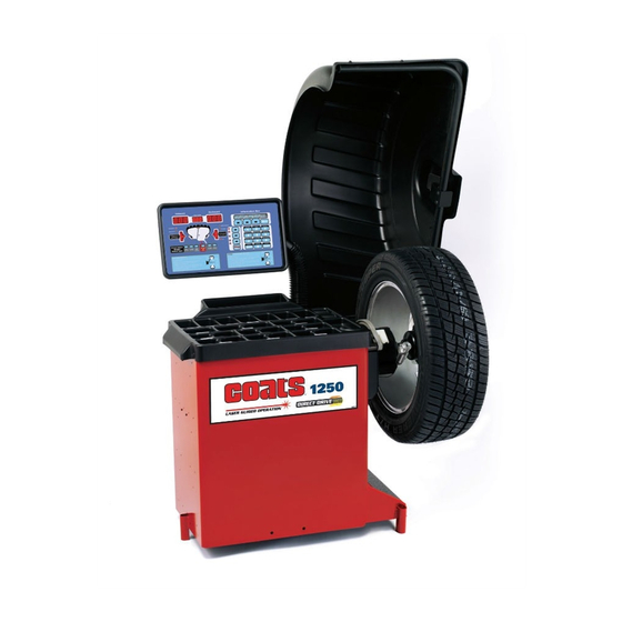
1250
See
Balancing Your
First Tire
on page 2.
1601 J. P . Hennessy Drive, LaVergne, TN USA 37086-3565 615/641-7533 800/688-6359 www.ammcoats.com
HENNESSY INDUSTRIES INC. Manufacturer of AMMCO
Wheel Balancer
Installation Instructions
Maintenance Instructions
READ these instructions before placing unit in
service KEEP these and other materials delivered
with the unit in a binder near the machine for
ease of reference by supervisors and operators.
®
, COATS
®
and BADA
®
Operating Instructions
Safety Instructions
®
Automotive Service Equipment and Tools.
An Optional Feature
Manual Part No.: 8114307 03
Revision:
06/06
Advertisement
Table of Contents

Related Manuals for HENNESSY INDUSTRIES Coats 1250


Summary of Contents for HENNESSY INDUSTRIES Coats 1250
- Page 1 1601 J. P . Hennessy Drive, LaVergne, TN USA 37086-3565 615/641-7533 800/688-6359 www.ammcoats.com Manual Part No.: 8114307 03 HENNESSY INDUSTRIES INC. Manufacturer of AMMCO ® , COATS ®...
-
Page 2: Important Safety Instructions
IMPORTANT SAFETY INSTRUCTIONS READ ALL INSTRUCTIONS 10. Wear proper clothing. Safety toe, non-slip Eye and face protection recommendations: footwear and protective hair covering to contain “Protective eye and face equipment is required to hair is recommended. Do not wear jewelry, loose be used where there is a reasonable probability of clothing, neckties, or gloves when operating the injury that can be prevented by the use of such... -
Page 3: Owner's Responsibility
Safety Owner’s Responsibility Definitions of Hazard Levels To maintain machine and user safety, the responsibil- Identify the hazard levels used in this manual with the ity of the owner is to read and follow these instruc- following definitions and signal words: tions: DANGER •... -
Page 4: Safety Notices And Decals
For additional radiation exposure. copies of either, or further information, con- In case of failure, the entire motor unit tact: must be replaced. Hennessy Industries, Inc. 1601 J.P . Hennessy Drive LaVergne, TN 37086-3565 (615) 641-7533 or (800) 688-6359 www.ammcoats.com NOTICE... -
Page 5: Table Of Contents
Table of Contents Important Safety Instructions ... . .ii Owner’s Responsibility ..... .iii Operator Protective Equipment . -
Page 6: Balancing Your First Tire
Balancing Your First Tire 1. Turn the machine OFF then ON 7. Raise hood after tire stops (resets machine). rotating. Note: The machine wakes up using standard Note: Wait for wheel to stop before raising the clip-on wheel weight locations (Clip 1 & Clip 2) hood. -
Page 7: Principle Operating Parts
Principle Operating Parts Know Your Unit Compare this illustration with the unit before placing it into service. Maximum performance and safety will be obtained only when all persons using the unit are fully trained in its parts and operation. Each user should learn the function and location, of all controls. -
Page 8: Power Switch
Power Switch When prompted by the instructions, use the offset arm (figure 5A), to enter A & D measurements auto- The ON/OFF decal, see figure 3, indicates the loca- matically. Pull offset arm out and up against the wheel tion of the ON/OFF switch at the back of the balancer. flange, hold it still at the clip-on weight location (figure 5B), against the wheel flange, and wait for the BEEP . - Page 9 Use the offset arm to measure A2 and D2 automati- Note: Throughout this manual wheel weights are cally when using the T2 - Tape (hidden Tape-A-Weight ® referred to as Clip-on or Tape-A-Weight™. Figure 7 location. Place the offset arm at the weight placement shows an example of each weight.
-
Page 10: Using The Lasers
Using The Lasers When using the Laser Guided Operation™ feature, enter the wheel measurements by grasping the offset When prompted by the instructions, use the knob on arm at the line laser and pulling it out and up to the the laser locator, to enter the hidden weight location wheel flange. -
Page 11: Laser Guided Operation™ System
Laser Guided Operation™ System 7. Next, rotate the wheel until the right plane center bar is steady and the two bars on either side blink. The operator must select T2 - Tape Laser Locator to activate the Laser Guided Operation™ feature, see Note: The laser locator dot will stop blinking. -
Page 12: Setting Wheel Dimensions (Dim)
Setting Wheel Dimensions (DIM) Entering Wheel Dimensions Manually Note: To manually enter the A2 offset, press SHIFT A. Before a wheel can be balanced, wheel dimensions To manually enter the D2 offset, press SHIFT D. must be entered into the computer. Wheel Offset - A Definition of Dimensions (DIM) 1. -
Page 13: Control Panel Function And Review
Control Panel Function and Review Weight Display Windows Information Box Mode LED Indicators Balancer Options Left Weight Position LED Bars Keypad Group Right Weight Position LED Bars Instructional Panel Direct Select™ & Wheel Cross-section Diagram Figure 13 - Control Panel Feature Reference Control Panel Quick Reference If you select/press …... -
Page 14: Weight Display And Weight Position Leds
Weight Display Windows Balancer Options Mode LED Indicators Keypad Group Left Weight Position LED Bars Instructional Pane Right Weight Position LED Bars Direct Select™ & Wheel Cross-section Diagram Information Box Figure 13 - Control Panel Feature Reference Weight Display and Weight Position LEDs Mode LED Indicators Two weight display windows (one inboard “Left The mode’s LED will illuminate to indicate the mode... -
Page 15: Direct Select™ Weight Location
Direct Select™ Weight Location Keypad Group Before spinning the wheel, use direct select to indi- The operator enters wheel data information, selects cate weight placement locations as follows: functions, and sets options using these keys. Note: When the machine is turned ON, the balancer “Numbered”... -
Page 16: Balancing Modes
Balancing Modes Static Modes Choose a static balance for wheel assemblies that A variety of wheel configurations can be balanced are not possible to balance dynamically or for narrow using this wheel balancer. Read through this section, it wheels. For example, a motorcycle wheel that has a will help in determining which mode and options are small wheel width. - Page 17 Begin by following the Laser Guided Operation™ pro- Patch Weight Balance - Use a static patch weight bal- cedure, steps 1 through 4 on page 7 . ance when there is a very large unbalance in a tire assembly or if a very large tire has a large unbalance. A 1.
-
Page 18: Mounting Wheel On Spindle Shaft
Mounting Wheel on Spindle Standard Back Cone Mounting Shaft Most original equipment and steel wheels can be mounted properly using this method. The wheel is cen- tered on a cone from the inner side of the hub. CAUTION 1. Place the cone spring onto the shaft with the large end towards the faceplate. -
Page 19: Standard Front Cone Mounting
Standard Front Cone Mounting Alternate Mounting A wheel should be centered by the outer side of the If the wheel has a protruding outer hub which will not hub only when the inner surface will not provide an permit the use of the pressure cup, or the cup will not accurate surface to center on. -
Page 20: Match Balance (Optimization)
Match Balance (Optimization) 5. Using a tire changer, rotate the tire 180 degrees on the rim. The Match Balance (Tire/Rim Weight Optimization) 6. Remount wheel assembly on the balancer. Press 2 procedure is used to determine the best mating of tire and rim that will result in the least amount of total on the control panel;... -
Page 21: Machine Calibration
Machine Calibration Maintenance Instructions Calibration The balancer requires only minor maintenance to keep the unit operating properly. 1. Mount a 14, 15, or 16-inch steel tire/wheel assem- bly on the balancer. A balanced tire/wheel is required. 1. Keep the display clean and clear. Use a damp cloth. -
Page 22: Diagnostic Procedures
6. Use only a lithium battery when replacing the bat- Troubleshooting tery located on the processor board. A COATS ® Service Technician may ask for information to help diagnose service concerns (Please contact CAUTION COATS ® directly at 1-800-688-9240 for the Certified Service Partner nearest you). -
Page 23: Installation Instructions
Installation Instructions Setup Receiving CAUTION The shipment should be thoroughly inspected as soon as it is received. The signed bill of lading is Do not use the control panel, control panel acknowledgement, for the carrier, of receipt in good base, accessory storage, faceplate, hood or condition of the shipment covered by our invoice. -
Page 24: Specifications
Specifications Features Balancing Modes • Automatic Data Entry for Offset and Diameter - Manual Entry Backup on all Parameters • Static-on-Screen™ Wheel Diameter Range • Four Fixed Function Keys, Seven Program Keys for 8 - 30 inches user Friendly Operation •... - Page 25 A A c c c c e e s s s s o o r r y y O O p p t t i i o o n n s s Contents Part Number Basic Kit 8114335 (28mm) 8114339 (40mm) Small Cone Medium Cone Large Cone...
- Page 26 22 • Important: Always read and follow the information box instructions.
- Page 27 Important: Always read and follow the information box instructions. • 23...
- Page 28 8114307 03 06/06 © Copyright 2005 Hennessy Industries and COATS All Rights Reserved Printed in USA...
Need help?
Do you have a question about the Coats 1250 and is the answer not in the manual?
Questions and answers