Table of Contents
Advertisement
Quick Links
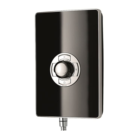
STYLE 3
electric shower
Installation and
operating
instructions
I
nstallers please note these InstructIons
are to be left wIth the user
Please read this book thoroughly and familiarise yourself with all
instructions before commencing installation and keep it for future reference.
The shower installation MUST be carried out by a suitably qualified person, in the
sequence of this instruction book.
2181075B - August 2014
Advertisement
Table of Contents

Related Manuals for Triton STYLE 3


Summary of Contents for Triton STYLE 3
- Page 1 STYLE 3 electric shower Installation and operating instructions nstallers please note these InstructIons are to be left wIth the user Please read this book thoroughly and familiarise yourself with all instructions before commencing installation and keep it for future reference.
- Page 2 INTRODUCTION - PLEASE READ PLEASE READ THIS IMPORTANT SAFETY INFORMATION Products manufactured by Triton are safe and without risk provided they are installed, used and maintained in good working order in accordance with our instructions and recommendations. WARNING: DO NOT operate shower if frozen, or suspected of being frozen. It must thaw out before using.
- Page 3 DO NOT operate the shower if water ceases to flow during use or if water has entered inside the unit because of an incorrectly fitted cover. WARNING: If restarting the shower immediately after stopping, be aware that a slug of IMPORTANT - GENERAL GUIDANCE NOTES hot water will be expelled for the first few seconds.
- Page 4 GENERAL ADVICE TO USERS IMPORTANT ADVICE TO USERS The following points will help you understand how the shower operates: a. The electric heating elements operate at a COMISSIONING ADVICE constant rate at your chosen power setting. It is the rate of the water passing through When first installed the unit will be empty.
-
Page 5: Table Of Contents
• DO NOT use abrasive or aggressive chemical cleaning products as this may affect the product surface finish and invalidate your guarantee. To check the product suitability for commercial and multiple installations, please contact Triton’s specification advisory service before installation. -
Page 6: Specifications
SECTION check list SPECIFICATIONS ELECTRICAL Nominal power - rating at 240V Nominal power - rating at 230V 8.5kW – (40A MCB rating) 7.8kW – (40A MCB rating) 9.5kW – (40A MCB rating) 8.7kW – (40A MCB rating) PLUMBING (see page 6 & 7 for water regulations) Supply Source Mains pressure cold water only Minimum running pressure and flow to the inlet... -
Page 7: Dimensions & Cable/Water Entry Points
SECTION DIMENSIONS & ENTRY POINTS check list Fig.1 DIMENSIONS 200mm 94mm ENTRY POINTS = Back = Others WATER Left: Top, Bottom, Side & Back. Right: Bottom, Side & Back. = Back = Others CABLE Left: Top, Bottom, Side & back. Right: None. -
Page 8: Electrical Requirements
SECTION ELECTRICAL REQUIREMENTS check list ELECTRICAL REQUIREMENTS Triton Showers, Fig.3 Triton Road, Nuneaton, Warwickshire, CV11 4NR WARNING! W-006-A xxxx THIS APPLIANCE MUST BE EARTHED The installation, supply cable and circuit protection must conform with BS 7671 (IEE wiring regulations) and be sufficient for the amperage required. - Page 9 SECTION Continued A 45 amp double pole isolating switch with 9.3 In any event, it is essential that individual a minimum contact gap of 3 mm in both site conditions are assessed by a competent poles must be incorporated in the circuit. electrician in order to determine the correct cable size and permissible circuit length.
-
Page 10: Installing The Shower
SECTION check list Installation - SITING OF THE SHOWER SITING OF THE SHOWER Mains electric supply (via double pole switch) The installation must be in accordance with Water Regulations/Bylaws - see page 2 for water specifications • If it is intended to operate the shower at Double pole pressures above the maximum or below the... - Page 11 SECTION Continued IMPORTANT: Water regulations (fig.6) WARNING • It is required that the showerhead be The shower MUST NOT be ‘constrained by a fixed or sliding attachment positioned where it will be so that it can only discharge water at a point subjected to freezing conditions.
-
Page 12: Plumbing Installation
SECTION check list Installation - PLUMBING INSTALLATION PLUMBING INSTALLATION Fig.7a Plumbing to be carried out before wiring • DO NOT use jointing compounds on any pipe fittings for the installation. • DO NOT solder fittings near the shower unit as heat can transfer along the pipework and damage components. -
Page 13: Electrical Installation
SECTION Installation - ELECTRICAL INSTALLATION check list ELECTRICAL INSTALLATION NOTE: Deviations from the designated entry IMPORTANT: Switch off the electricity supply at the mains before proceeding. points will invalidate product approvals. The cable entry points are listed on page 3. •... - Page 14 SECTION Continued • Offer the unit to the wall and secure the Fig.10 fixing screws into position. DO NOT fully tighten the screws at this stage, as the fixing holes are elongated to allow for out of square adjustment after the plumbing connections have been completed.
- Page 15 SECTION Continued • Route the cable into the shower unit for connection to the terminal block (fig.11) as follows: Terminal block Earth cable to terminal marked Neutral cable to terminal marked N Live cable to terminal marked • Once the cables have been installed the two trimplates will need to be fitted.
-
Page 16: Fitting The Cover
SECTION check list Installation - FITTING THE COVER Fig.13 PLEASE NOTE Before normal operation of the shower, it is essential the following commissioning procedure is completed correctly. IMPORTANT DO NOT connect the 10-way ribbon cable before the commissioning procedure has been completed. FITTING THE COVER Fitting The Cover - valve &... -
Page 17: Commissioning Procedure
SECTION !! IMPORTANT !! COMMISSIONING check list WARNING Fig.15 Before normal operation of the shower, it is essential the following commissioning procedure is completed correctly. COMMISSIONING PROCEDURE The first operation of the shower is intended to flush out any remaining unit debris, and to make sure the heater unit contains water before the elements are switched on. -
Page 18: Connecting The Pcb Cable
SECTION check list CONNECTING THE PCB CABLE CONNECTING THE PCB CABLE Fig.17 & REFITTING THE COVER IMPORTANT: After connecting the PCB cable, please check the following before refitting the cover: 1. All plumbing connections are watertight. 2. Terminal block screws are fully tightened. 3. -
Page 19: User Operating Instructions
SECTION USER OPERATING INSTRUCTIONS check list OPERATING THE SHOWER - (fig.18) • When the electricity supply to the shower is switched on at the isolating switch, the red “power” indicator will light under button A. To start the shower C - Economy NOTE: the shower starts as a default on the High button heat setting if the Start/Stop button is used. - Page 20 SECTION Continued To adjust the shower temperature - Fig.19 Economy and High settings only Temperature control knob • The water temperature is altered by increasing or decreasing the flow rate of the water through the shower via the temperature control (fig.19). •...
-
Page 21: Operating Functions
SECTION Continued OPERATING FUNCTIONS (fig.20) Power on indicator (red) • When the electricity supply to the shower is switched on at the isolating switch, the power indicator will light up. Low pressure indication (red flashing) If the water pressure has fallen below the minimum required for correct operation of the shower, resulting in the low pressure cut-out operating, the following will happen. -
Page 22: Cleaning The Filter - Installers & Service Engineers Only
Instructions for installers and service engineers only INSTRUCTIONS FOR INSTALLERS AND SERVICE ENGINEERS ONLY Instructions for installers and service engineers only CLEANING THE FILTER It is recommended that the filter is periodically cleaned in order to maintain the performance of the shower. -
Page 23: Fault Finding/Troubleshooting
FAULT FINDING/TROUBLESHOOTING FAULT FINDING Important: Switch off the electricity at the mains supply and remove the circuit fuse before attempting any fault finding inside the unit. Problem/Symptom Cause Action/Cure Problem/Symptom Cause Action/Cure 1 Shower inoperable, 1.1 Interrupted power 1.1.1 Blown fuse or circuit breaker. Check supply no water flow. - Page 24 When fitting a new PRD, follow the commissioning procedure. It is advised all electrical maintenance/repairs to the shower should be carried out by a suitably qualified person. In the unlikely event of a fault occurring please contact Triton Customer Service. DO NOT remove the shower from the installation.
-
Page 25: Spare Parts
SPARE PARTS SPARE PARTS Thermal cut-out (TCO) ....22012750 Heater can assembly 8.5kW ...........83314510 9.5kW ...........83314520 Solenoid valve - ......P27410800 stabilizer valve assembly ....... Pressure switch assembly .... P27411001 . Switch actuator disk .......7054237 Pressure relief device (PRD) ...82800450 Terminal block & wires ....S27411003 Water inlet ........ - Page 26 WEEE Directive – Policy Statement As a producer and a supplier of electric showers, Triton Showers is committed to the protection of the environment via our own environmental policy and the compliance with the WEEE directive. Triton Showers is fully registered with the Environment Agency under the following schemes:...
-
Page 27: Shower Controls - Quick User Guide
SHOWER CONTROLS - QUICK USER GUIDE To START or STOP your shower. The red power light (under button A) will illuminate. To START the shower - button A, B, C or D can be pressed and water will flow from the shower. •... -
Page 28: Service Policy/Uk Guarantee
Triton is a division of Norcros Group (Holdings) Limited E-mail: serviceenquiries@tritonshowers.co.uk Extended Warranty AVAILABLE NOW. Call 0844 980 0740 for more details. TRITON reserve the right to change product specification without prior notice. E&OE. © TRITON SHOWERS 2014 12-03-14...
Need help?
Do you have a question about the STYLE 3 and is the answer not in the manual?
Questions and answers