Table of Contents
Advertisement
Quick Links
www.ti.com
User's Guide
MSPM0G3507 LaunchPad Development Kit
‑ MSPM0G3507)
(LP
The
MSPM0G3507 LaunchPad
microcontroller
(MCU). The LaunchPad kit contains everything needed to start developing on the MSPM0Gxxxx
microcontroller platform, including an onboard debug probe for programming, debugging, and
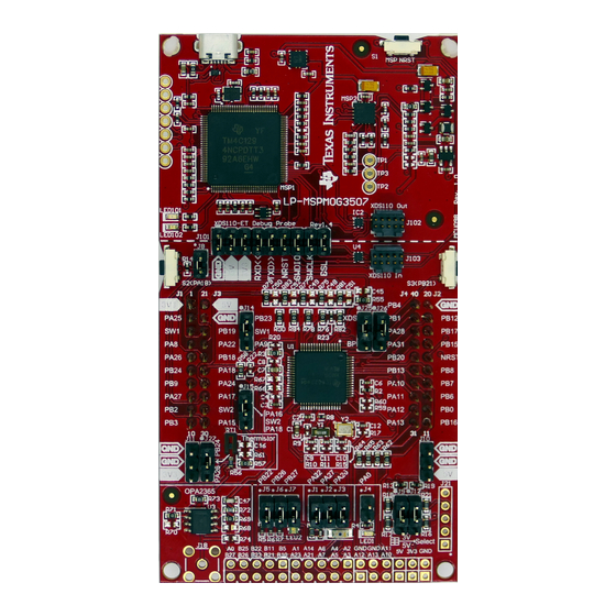
technology. The board also features onboard buttons, LEDs, an RGB LED, a light sensor, and a temperature
sensor.
The following figure shows the LP-MSPM0G3507 LaunchPad Development Kit.
SLAU873A – JANUARY 2023 – REVISED MARCH 2023
Submit Document Feedback
ABSTRACT
™
development kit
is an easy-to-use evaluation module for the
MSPM0G3507 LaunchPad Development Kit
Copyright © 2023 Texas Instruments Incorporated
MSPM0G3507 LaunchPad Development Kit (LP
MSPM0G3507
EnergyTrace
™
‑ MSPM0G3507)
1
Advertisement
Table of Contents

Related Manuals for Texas Instruments MSPM0G3507


Summary of Contents for Texas Instruments MSPM0G3507
- Page 1 ™ technology. The board also features onboard buttons, LEDs, an RGB LED, a light sensor, and a temperature sensor. The following figure shows the LP-MSPM0G3507 LaunchPad Development Kit. MSPM0G3507 LaunchPad Development Kit ‑ MSPM0G3507) SLAU873A – JANUARY 2023 – REVISED MARCH 2023...
-
Page 2: Table Of Contents
, and µVision are registered trademarks of Arm Limited. All trademarks are the property of their respective owners. ‑ MSPM0G3507) MSPM0G3507 LaunchPad Development Kit (LP SLAU873A – JANUARY 2023 – REVISED MARCH 2023 Submit Document Feedback Copyright © 2023 Texas Instruments Incorporated... -
Page 3: Getting Started
1.4 First Step: Out-of-Box Experience An easy way to get started with the EVM is by using the preprogrammed out-of-box code. This code demonstrates some key features of the EVM and is meant to be used with the LP-MSPM0G3507 out-of-box demo GUI. -
Page 4: Next Steps: Looking Into The Provided Code
LaunchPad development kit. SysConfig for MSPM0 is another graphical tool that can be utilized to easily and quickly setup your MSPM0G3507 device, pins, and peripherals to fit your development needs. The out-of-box source code and more code examples are provided and available on the download page. Code is licensed under BSD, and TI encourages reuse and modifications to fit specific needs. -
Page 5: Hardware
Hardware 2 Hardware Figure 2-1 shows an overview of MSPM0G3507 LaunchPad development kit hardware. Reset USB to PC MSPM0G3507 reset XDS110 onboard debug probe Enables debugging and EnergyTrace Technology programming as well as Real-time power consumption and communication to the PC. The... - Page 6 MSPM0G3507 pin extension header J23-J28 See schematic for details No external connection (unlabeled – bottom of board) ‑ MSPM0G3507) MSPM0G3507 LaunchPad Development Kit (LP SLAU873A – JANUARY 2023 – REVISED MARCH 2023 Submit Document Feedback Copyright © 2023 Texas Instruments Incorporated...
-
Page 7: Block Diagram
2.3 Hardware Features 2.3.1 MSPM0G3507 MCU The MSPM0G3507 devices provide 128KB of embedded flash program memory with built-in error correction code (ECC) and 32KB of SRAM with hardware parity. The devices also incorporate a memory protection unit, 7-channel DMA, math accelerator, and a variety of high-performance analog peripherals such as two 12-bit 4-Msps ADCs, a configurable internal shared voltage reference, one 12-bit DAC, three high speed comparators with built-in reference DACs, two zero-drift op-amps with programmable gain, and one general-purpose amplifier. - Page 8 2.3.2 XDS110-ET Onboard Debug Probe With EnergyTrace Technology To keep development easy and cost effective, TI’s LaunchPad development kits integrate an onboard debug probe, which eliminates the need for expensive programmers. The MSPM0G3507 has the XDS110 debug probe (see Figure 2-4), which is a simple and low-cost debugger that supports all MSPM0 device derivatives.
- Page 9 Backchannel UART: The target M0G3507 sends data through this signal. The arrows indicate the direction of the TXD>> signal ‑ MSPM0G3507) SLAU873A – JANUARY 2023 – REVISED MARCH 2023 MSPM0G3507 LaunchPad Development Kit (LP Submit Document Feedback Copyright © 2023 Texas Instruments Incorporated...
- Page 10 On the target MSPM0G3507 side, the backchannel is connected to the UART0 module. The XDS110-ET has a configurable baud rate; therefore, it is important that the PC application configures the baud rate to be the same as what is configured on the UART0.
- Page 11 The capacitor and resistor network associated with the OPA is not populated by default. This allows the user to populate with passive values to fit the specific application needs. ‑ MSPM0G3507) SLAU873A – JANUARY 2023 – REVISED MARCH 2023 MSPM0G3507 LaunchPad Development Kit (LP Submit Document Feedback Copyright © 2023 Texas Instruments Incorporated...
- Page 12 The jumpers can be removed to place the photodiode out of circuit so the MSPM0 connections can be used for other evaluation purposes. ‑ MSPM0G3507) MSPM0G3507 LaunchPad Development Kit (LP SLAU873A – JANUARY 2023 – REVISED MARCH 2023 Submit Document Feedback...
-
Page 13: Power
1. Remove the 3V3 jumper in the J101 isolation block, and attach an ammeter across this jumper. 2. Consider the effect that the backchannel UART and any circuitry attached to the MSPM0G3507 may have on the current draw. Consider disconnecting these at the isolation jumper block, or at least consider their current sinking and sourcing capability in the final measurement. -
Page 14: Clocking
LaunchPad development kits and BoosterPack plug-in modules across the TI ecosystem. While most BoosterPack plug-in modules are compliant with the standard, some are not. The MSPM0G3507 LaunchPad development kit is compatible with all 40-pin BoosterPack plug-in modules that are compliant with the standard. -
Page 15: Resources
Section 4.1.2 for more information. 4.3 MSPM0G3507 MCU 4.3.1 Device Documentation At some point, you will probably want more information about the MSPM0G3507 device. For every MSP device, the documentation is organized as shown in Table 4-1. Table 4-1. Device Documentation... -
Page 16: Community Resources
MSPM0G3507 MCU. Every MSP derivative has a set of these code examples. When starting a new project or adding a new peripheral, these examples serve as a great starting point. -
Page 17: Schematics
Schematics 5 Schematics ‑ MSPM0G3507) SLAU873A – JANUARY 2023 – REVISED MARCH 2023 MSPM0G3507 LaunchPad Development Kit (LP Submit Document Feedback Copyright © 2023 Texas Instruments Incorporated... - Page 18 Schematics www.ti.com ‑ MSPM0G3507) MSPM0G3507 LaunchPad Development Kit (LP SLAU873A – JANUARY 2023 – REVISED MARCH 2023 Submit Document Feedback Copyright © 2023 Texas Instruments Incorporated...
- Page 19 Schematics ‑ MSPM0G3507) SLAU873A – JANUARY 2023 – REVISED MARCH 2023 MSPM0G3507 LaunchPad Development Kit (LP Submit Document Feedback Copyright © 2023 Texas Instruments Incorporated...
- Page 20 Schematics www.ti.com ‑ MSPM0G3507) MSPM0G3507 LaunchPad Development Kit (LP SLAU873A – JANUARY 2023 – REVISED MARCH 2023 Submit Document Feedback Copyright © 2023 Texas Instruments Incorporated...
- Page 21 Schematics ‑ MSPM0G3507) SLAU873A – JANUARY 2023 – REVISED MARCH 2023 MSPM0G3507 LaunchPad Development Kit (LP Submit Document Feedback Copyright © 2023 Texas Instruments Incorporated...
- Page 22 Schematics www.ti.com ‑ MSPM0G3507) MSPM0G3507 LaunchPad Development Kit (LP SLAU873A – JANUARY 2023 – REVISED MARCH 2023 Submit Document Feedback Copyright © 2023 Texas Instruments Incorporated...
- Page 23 Schematics ‑ MSPM0G3507) SLAU873A – JANUARY 2023 – REVISED MARCH 2023 MSPM0G3507 LaunchPad Development Kit (LP Submit Document Feedback Copyright © 2023 Texas Instruments Incorporated...
-
Page 24: Revision History
Changes from Revision * (January 2023) to Revision A (March 2023) Page • Updated all images in Section 5 Schematics ....................17 ‑ MSPM0G3507) MSPM0G3507 LaunchPad Development Kit (LP SLAU873A – JANUARY 2023 – REVISED MARCH 2023 Submit Document Feedback Copyright © 2023 Texas Instruments Incorporated... - Page 25 TI products. TI’s provision of these resources does not expand or otherwise alter TI’s applicable warranties or warranty disclaimers for TI products. TI objects to and rejects any additional or different terms you may have proposed. IMPORTANT NOTICE Mailing Address: Texas Instruments, Post Office Box 655303, Dallas, Texas 75265 Copyright © 2023, Texas Instruments Incorporated...
Need help?
Do you have a question about the MSPM0G3507 and is the answer not in the manual?
Questions and answers