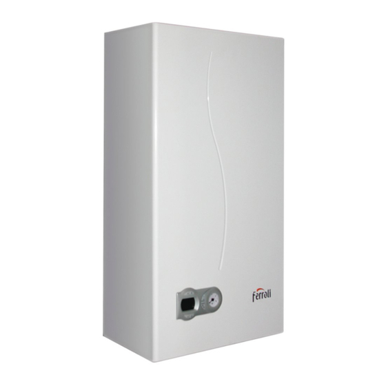
Ferroli DIVAtech F 24 D Instructions For Use, Installation & Maintenance
Hide thumbs
Also See for DIVAtech F 24 D:
Summary of Contents for Ferroli DIVAtech F 24 D
- Page 1 DIVAtech F 24 D Ø110÷120 Ø24.5 Ø30 Ø24.5 Ø30 Ø24.5 EN - INSTRUCTIONS FOR USE, INSTALLATION AND MAINTENANCE...
-
Page 2: General Warnings
2. OPERATING INSTRUCTIONS 2.1 Introduction DIVAtech F 24 D is a high-efficiency heat generator for heating and domestic hot water production, running on natural gas, equipped with an open-flue burner with electronic ig- nition, sealed chamber with forced ventilation, and microprocessor control system, de- fig. - Page 3 DIVAtech F 24 D Domestic hot water (DHW) temperature adjustment Adjustments from Remote Timer Control Use the DHW buttons (details 1 and 2 - fig. 1) to adjust the temperature from a min. of If the Remote Timer Control (optional) is connected to the boiler, the above ad- 40°C to a max.
-
Page 4: Installation
DIVAtech F 24 D 3. INSTALLATION Accessing the electrical terminal block 3.1 General Instructions The electrical terminal block can be accessed after removing the casing. The layout of the terminals for the various connections is also given in the wiring diagram in fig. 22. - Page 5 DIVAtech F 24 D Connection with coaxial pipes Connection with separate pipes fig. 10 - Examples of connection with coaxial pipes ( = Air / = Fumes) Table. 2 - Typology fig. 12 - Examples of connection with separate pipes (...
-
Page 6: Service And Maintenance
• Press the Eco/Comfort button for 2 seconds to return to the TEST mode. If the boiler is to be connected DIVAtech F 24 D to a collective flue or to a single flue with • Deactivate the TEST mode (see cap. 4.1). -
Page 7: Troubleshooting
DIVAtech F 24 D 4.4 Troubleshooting A - Upstream pressure point Diagnostics B - Downstream pressure point The boiler is equipped with an advanced self-diagnosis system. In case of a boiler fault, I - Gas valve electrical connection the display will flash together with the fault symbol (detail 11 - fig. 1) indicating the fault R - Gas outlet code. -
Page 8: Technical Data And Characteristics
37 Cold water inlet filter 278 Double sensor (Safety + Heating) 5.1 General view and main components fig. 20 - Heating Circuit fig. 21 - DHW Circuit fig. 19 - General view DIVAtech F 24 D cod. 3541B072 - Rev. 00 - 11/2016... -
Page 9: Technical Data Table
DIVAtech F 24 D 5.3 Technical data table 5.4 Diagrams Pressure - power diagrams DIVAtech F 24 D mbar Data Unit DIVAtech F 24 D Max. heating capacity 25.8 Min. heating capacity Max. Heat Output in heating 24.0 Min. Heat Output in heating Max. - Page 10 DIVAtech F 24 D 5.5 Wiring diagram LC32 ABM01 ° ° ° 230V 50 Hz fig. 22 - Electrical circuit Important: Before connecting the room thermostat or the remote timer control, remove the jumper on the terminal block. cod. 3541B072 - Rev. 00 - 11/2016...
-
Page 11: Declaration Of Conformity
Declaration of conformity Manufacturer declares that this unit complies with the following EU directives: • Gas Appliance Directive 2009/142 • Efficiency Directive 92/42 • Low Voltage Directive • Electromagnetic Compatibility Directive... - Page 12 FERROLI S.p.A. Via Ritonda 78/a 37047 San Bonifacio - Verona - ITALY www.ferroli.it...


Need help?
Do you have a question about the DIVAtech F 24 D and is the answer not in the manual?
Questions and answers