Table of Contents
Advertisement
Quick Links
Z8F80388764
TLE989x EvalBoard with TQFP/LQFP spring
socket v01_1 User Guide
About this document
Scope and purpose
This user guide is intented to help users operating the TLE989x EvalBoard with TQFP/LQFP spring socket, which
is designed to evaluate hardware and software functionalities of the MOTIX™ MCU TLE988x and TLE989x family.
Additional information is provided about the board's layout, jumper settings, interface and debug options. It
introduces the evaluation platform as well as how to write software and download it to the MOTIX™ MCU
TLE988x or TLE989x.
Intended audience
This document is intended for anyone using the TLE989x EvalBoard with TQFP/LQFP spring socket.
Evaluation Board
This board will be used during design in, for evaluation and measurement of characteristics, and proof of data
sheet specifications.
Note:
PCB and auxiliary circuits are NOT optimized for final customer design.
Please read the Important notice and the Safety precautions and the Warnings
www.infineon.com
page 1 of 50
2023-05-16
Advertisement
Table of Contents

Related Manuals for Infineon TLE989 EVALB LQFP Series


Summary of Contents for Infineon TLE989 EVALB LQFP Series
-
Page 1: About This Document
This board will be used during design in, for evaluation and measurement of characteristics, and proof of data sheet specifications. Note: PCB and auxiliary circuits are NOT optimized for final customer design. Please read the Important notice and the Safety precautions and the Warnings www.infineon.com page 1 of 50 2023-05-16... -
Page 2: Important Notice
Boards provided by Infineon Technologies. The design of the Evaluation Boards and Reference Boards has been tested by Infineon Technologies only as described in this document. The design is not qualified in terms of safety requirements, manufacturing and operation over the entire operating temperature range or lifetime. -
Page 3: Safety Precautions
TLE989x EvalBoard with TQFP/LQFP spring socket v01_1 User Guide Safety precautions Safety precautions Note: Please note the following warnings regarding the hazards associated with development systems. Table 1 Safety precautions Caution: The heat sink and device surfaces of the evaluation or reference board may become hot during testing. -
Page 4: Table Of Contents
Debugging ............................22 Assembly Options ........................23 Software toolchain ........................ 25 Keil µVision 5 ............................25 Infineon Config Wizard .......................... 25 TLE988x_9x SDK ............................ 25 Debug connection setup ........................25 Design Files .......................... 27 BOM of the TLE989x EvalBoard with TQFP/LQFP spring socket ............27 Schematics of the TLE989x EvalBoard with TQFP/LQFP spring socket .......... -
Page 5: The Board At A Glance
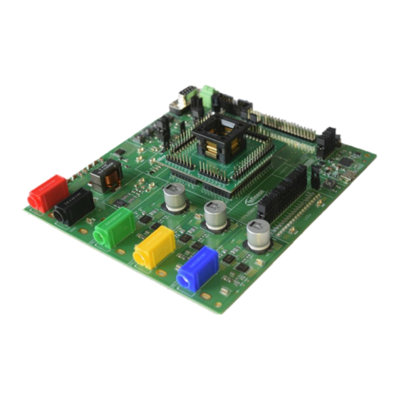
The board at a glance The board at a glance This board is designed to provide a simple, easy-to-use tool for getting familiar with Infineon’s MOTIX™ MCU IC TLE988x and TLE989x devices. Sockets for LQFP64 and TQFP48 package provide the possibility to test and evaluate all ICs of the MOTIX™ MCU TLE988x and TLE989x family. -
Page 6: Main Features
TLE989x EvalBoard with TQFP/LQFP spring socket v01_1 User Guide The board at a glance Figure 1 Block Diagram Figure 2 Hardware Implementation Main features Compatible connector for socket board of LQFP64 pin package and TQFP48 pin package • Direct placement option for LQFP64 pin package device •... -
Page 7: Technical Data
TLE989x EvalBoard with TQFP/LQFP spring socket v01_1 User Guide The board at a glance Technical data Technical data is specified in Table 2. Current capability is limited by the default assembly of banana plugs and the 10 W shunt resistor. Higher current capability up to 30 A can be reached by adjusting the battery and motor connectors, as well as replacing the shunt resistor. -
Page 8: System And Functional Description
TLE989x EvalBoard with TQFP/LQFP spring socket v01_1 User Guide System and functional description System and functional description Board Information 2.1.1 Connectors MON1 MON2* MON3* FIFO* VBAT QRP1 CPI 4 CPI 2 CPI 8 CPI 6 VDH# CANH MONx RSUP LE D_S UP CANL CM22 CM11... - Page 9 TLE989x EvalBoard with TQFP/LQFP spring socket v01_1 User Guide System and functional description connect a motor. For applications with high current, cables can also be soldered directly to pads next to the banana jacks TLE988x_TLE989x Pin headers to connect on of the TLE988x_TLE989x Socket boards Socket CAN D-SUB Standard D-SUB DE-09 connector to connect CAN communication lines to the device...
-
Page 10: Test Points
TLE989x EvalBoard with TQFP/LQFP spring socket v01_1 User Guide System and functional description 2.1.2 Test points MON1 MON2* MON3* FIFO* VBAT QRP1 CPI 4 CPI 2 CPI 8 CPI 6 VDH# CANH MONx RSUP LE D_S UP CANL CM22 CM11 CM31 CM21 VDDEXT... -
Page 11: Leds
TLE989x EvalBoard with TQFP/LQFP spring socket v01_1 User Guide System and functional description Phase 1, 2, 3 and Vias which can be used as testpoints to measure motor phase voltages with a probe tip 12 x GND and GND spring (indicated in orange in Figure 4) GH1, GH2, GH3... - Page 12 TLE989x EvalBoard with TQFP/LQFP spring socket v01_1 User Guide System and functional description Table 5 LEDs LED_SUP Indicates supply voltage is active LED_FIFO Indicates FIFO is active LEDCOM Indicates on-board debugger communication is active LED0.0 Can be connected to GPIO P0.0 with jumper JP8, as described in 2.1.4. Since this pin is used for programming the device, it is disconnected by default;...
-
Page 13: Jumpers
TLE989x EvalBoard with TQFP/LQFP spring socket v01_1 User Guide System and functional description 2.1.4 Jumpers MON1 MON2* MON3* FIFO* VBAT QRP1 CPI4 CPI2 CPI8 CPI6 VDH# CANH MONx RSUP LED_SUP CANL CM22 CM11 CM31 CM21 ILoadVSD ILoadVS VDDEXT P2.5 POTI POTI Sig. - Page 14 TLE989x EvalBoard with TQFP/LQFP spring socket v01_1 User Guide System and functional description Set jumper to select analog pin of device for the Potentiometer signal. Open it to disconnect Potentiometer signal from analog pin of device. Jumper is set to P2.6 by default Set jumper to connect VDDEXT to VAREF# in order to supply VAREF with VDDEXT.
-
Page 15: Push Buttons
TLE989x EvalBoard with TQFP/LQFP spring socket v01_1 User Guide System and functional description 2.1.5 Push Buttons MON1 MON2* MON3* FIFO* VBAT QRP1 CPI4 CPI2 CPI8 CPI6 VDH# CANH MONx RSUP LED_SUP CANL CM22 CM31 CM11 CM21 VDDEXT P2.5 ILoadVSD ILoadVS POTI POTI Supply... -
Page 16: Interfaces
TLE989x EvalBoard with TQFP/LQFP spring socket v01_1 User Guide System and functional description Interfaces 2.2.1 Socket boards Two different socket boards are available for the TLE989x EvalBoard with TQFP/LQFP spring socket, one for LQFP64 package and one for TQFP48 package. Devices of the same package can be exchanged with the plastic spring socket on the socket boards. -
Page 17: Motor Power Stage
TLE989x EvalBoard with TQFP/LQFP spring socket v01_1 User Guide System and functional description For the LQFP64 package there is the option to solder the device directly onto the base board. If the device is placed, all passive components inside the socket area and the external oscillator need to be placed as well. If components are assembled inside the socket area on the base board, no socket board can be used. -
Page 18: Can
Pinout of CAN D-SUB interface The CAN_BSL interface is a 16-pin header (2 x 8) with 2.54 mm pitch and can be used to program the device via CAN with the Infineon uIO stick (see www.infineon.com/uio or www.hitex.com/uio). The pinout for the CAN_BSL interface is depicted in the figure below. - Page 19 TLE989x EvalBoard with TQFP/LQFP spring socket v01_1 User Guide System and functional description The CANH/L terminal block can be used to connect CANH and CANL cables with clamps. If jumper cables are used, they can also be connected directly to pin header X1. The pinout for X1 and the CANH/L terminal block is depicted in the figure below.
-
Page 20: Potentiometer
TLE989x EvalBoard with TQFP/LQFP spring socket v01_1 User Guide System and functional description Figure 17 Placement option for common mode choke 2.2.4 Potentiometer A potentiometer is available on the board, which can either be supplied by VDDEXT or VDDP of the device. Set jumper JP5 accordingly. - Page 21 TLE989x EvalBoard with TQFP/LQFP spring socket v01_1 User Guide System and functional description Figure 20 Pinout of X2 (left) and X3 (right) Pin P2.0 and P2.1 are not connected to the device by default. To connect them a placement option for 0Ω resistors R10 and R11 is available.
-
Page 22: Debugging
TLE989x EvalBoard with TQFP/LQFP spring socket v01_1 User Guide System and functional description 2.2.7 Debugging On the board a SEGGER J-Link debugger is available for debugging, which can be connected via an USB cable. Alternatively, an off-board debugger like the ARM®KEIL ULINK2 or the XMC™ Link can be used via the SWD interface. -
Page 23: Assembly Options
TLE989x EvalBoard with TQFP/LQFP spring socket v01_1 User Guide Assembly Options Assembly Options MON1 MON2* MON3* FIFO* VBAT QRP1 CPI 4 CPI 2 CPI 8 CPI 6 VDH# CANH MONx RSUP LE D_S UP CANL CM22 CM11 CM31 CM21 VDDEXT P2.5 ILoa dVS D ILoa dVS... - Page 24 TLE989x EvalBoard with TQFP/LQFP spring socket v01_1 User Guide Assembly Options Component Description C_VDH VDH decoupling capacitor. Needs to be assembled, if no socketboard is used CVS1 VS decoupling capacitor. Needs to be assembled, if no socketboard is used External oscillator. Needs to be assembled, if no socketboard is used RX02 Oscillator resistor.
-
Page 25: Software Toolchain
Infineon Config Wizard In addition to the IDE, Infineon provides a solution to speed-up the IC programming, the Config Wizard. This tool is designed for code configuration in combination with the IDE. Infineon “Config Wizard for MOTIX™ MCU” can be downloaded via the Infineon Toolbox. The Infineon Toolbox is a central place to download and update all your Infineon tools. - Page 26 TLE989x EvalBoard with TQFP/LQFP spring socket v01_1 User Guide Software toolchain Figure 25 Debug and flash configuration If the board is connected successfully, the Arm® IDCODE will be visible in the SW Device Window. If connection fails, “Connect & Reset Options” and “Port” window has to be checked. 26 of 50 2023-05-16...
-
Page 27: Design Files
TLE989x EvalBoard with TQFP/LQFP spring socket v01_1 User Guide Design Files Design Files BOM of the TLE989x EvalBoard with TQFP/LQFP spring socket For the design of the TLE989x EvalBoard with TQFP/LQFP spring socket automotive qualified components are used. The complete BOM is shown below including non-fitted components. Designator Description Quantity... - Page 28 SOD323 DUSBM, DUSBP Bi-directional TVS Protection 2 ESD231-B1-W0201 Device, 5.5V, 3.5pF Banana Socket, Black, 15.3mm 1 571-0100 Pitch Infineon XMC4200 with ARM 1 XMC4200Q48K256ABX Cortex-M4 Core, VQFN-48 UMA1 Fixed Linear Voltage Post 1 TLS202B1MBV33 Regulator, 3.3V IC3, IC5 Dual-Bit, Dual-Supply Voltage...
- Page 29 TLE989x EvalBoard with TQFP/LQFP spring socket v01_1 User Guide Design Files Designator Description Quantity Manufacturer Order Automotive Number Qualified IC4, IC6 Single-bit noninverting bus 2 SN74LVC1T45DCKR transceiver ILoadVS, ILoadVSD, Through hole .025'' SQ Post 6 HTSW-102-07-L-S JP1, JP2, JP7, X1 Header, 2.54mm pitch, 2 pin, vertical, single row JP3, JP4...
- Page 30 TLE989x EvalBoard with TQFP/LQFP spring socket v01_1 User Guide Design Files Designator Description Quantity Manufacturer Order Automotive Number Qualified LED_FIFO, LED_SUP, LEDCOM LED_VDDEXT, Standard SMD LED, 0603, 2 TLMP1100-GS08 AEC Q101 LED_VDDP Green Inductor, IND / STD / 6.8uH / 1 XAL1510-682MED AEC Q200 36A / 20% / -40°C to 125°C /...
- Page 31 TLE989x EvalBoard with TQFP/LQFP spring socket v01_1 User Guide Design Files Designator Description Quantity Manufacturer Order Automotive Number Qualified ROP1, ROP2 Standard Thick Film Chip 2 CRCW080512R0FK AEC Q200 Resistor, 0805, 12R RPDLS1, RPDLS2, Standard Thick Film Chip 5 CRCW040210K0FK AEC Q200 RPDLS3, RPORST, Resistor, 0402, 10k...
- Page 32 TLE989x EvalBoard with TQFP/LQFP spring socket v01_1 User Guide Design Files Designator Description Quantity Manufacturer Order Automotive Number Qualified XA, XC, XD Through hole .025'' SQ Post 3 TSW-116-07-L-S Header, 2.54mm pitch, 16 pin, vertical, single row XB1, XB2 Through hole .025'' SQ Post 2 TSW-108-07-L-S Header, 2.54mm pitch, 8 pin, vertical, single row...
-
Page 33: Schematics Of The Tle989X Evalboard With Tqfp/Lqfp Spring Socket
TLE989x EvalBoard with TQFP/LQFP spring socket v01_1 User Guide Design Files Schematics of the TLE989x EvalBoard with TQFP/LQFP spring socket 33 of 50 2023-05-16... - Page 34 TLE989x EvalBoard with TQFP/LQFP spring socket v01_1 User Guide Design Files Figure 26 TLE989x EvalBoard with TQFP/LQFP spring socket, sheet 1, TLE988x_TLE989x_baseBoard_v1_1 34 of 50 2023-05-16...
- Page 35 TLE989x EvalBoard with TQFP/LQFP spring socket v01_1 User Guide Design Files Figure 27 TLE989x EvalBoard with TQFP/LQFP spring socket, sheet 2, TLE98xy 35 of 50 2023-05-16...
- Page 36 TLE989x EvalBoard with TQFP/LQFP spring socket v01_1 User Guide Design Files Power VDH# VDH# VDH# High side CGDHS RSBHS 33pF RGHS CDCA CDCB 100nF 680uF CSBHS CGSHS 10nF RGSHS 4.7nF 100k Phase_TP Phase Phase BAS52-02V 470pF Low side CGDLS RSBLS 33pF RGLS CSBLS...
- Page 37 TLE989x EvalBoard with TQFP/LQFP spring socket v01_1 User Guide Design Files Figure 29 TLE989x EvalBoard with TQFP/LQFP spring socket, sheet 4, debugger_interface 37 of 50 2023-05-16...
- Page 38 TLE989x EvalBoard with TQFP/LQFP spring socket v01_1 User Guide Design Files Figure 30 TLE989x EvalBoard with TQFP/LQFP spring socket, sheet 5, Interfaces 38 of 50 2023-05-16...
- Page 39 TLE989x EvalBoard with TQFP/LQFP spring socket v01_1 User Guide Design Files Figure 31 TLE989x EvalBoard with TQFP/LQFP spring socket, sheet 6, BoardSupply 39 of 50 2023-05-16...
-
Page 40: Layout Of The Tle989X Evalboard With Tqfp/Lqfp Spring Socket
TLE989x EvalBoard with TQFP/LQFP spring socket v01_1 User Guide Design Files Layout of the TLE989x EvalBoard with TQFP/LQFP spring socket Figure 32 TLE989x EvalBoard with TQFP/LQFP spring socket, layer1 (Top layer, signal) 40 of 50 2023-05-16... - Page 41 TLE989x EvalBoard with TQFP/LQFP spring socket v01_1 User Guide Design Files Figure 33 TLE989x EvalBoard with TQFP/LQFP spring socket, layer2 (Middle layer, power) 41 of 50 2023-05-16...
- Page 42 TLE989x EvalBoard with TQFP/LQFP spring socket v01_1 User Guide Design Files Figure 34 TLE989x EvalBoard with TQFP/LQFP spring socket, layer3 (Middle layer, GND) 42 of 50 2023-05-16...
- Page 43 TLE989x EvalBoard with TQFP/LQFP spring socket v01_1 User Guide Design Files Figure 35 TLE989x EvalBoard with TQFP/LQFP spring socket, layer4 (Bottom layer, signal) 43 of 50 2023-05-16...
-
Page 44: Schematics Of The Lqfp64 Socketboard
TLE989x EvalBoard with TQFP/LQFP spring socket v01_1 User Guide Design Files Schematics of the LQFP64 Socketboard P0.1 P0.2 P0.3 P0.4 P0.5 CP2L P0.6 CP2H P0.7 P0.8 CP1H P0.9 CP1L CSA_N CSA_P P2.2 P2.3 FIFO P2.4 MON1 P2.5 MON2 P2.6 MON3 Figure 36 TLE988x_TLE989x LQFP64 Socketboard Schematics 44 of 50... -
Page 45: Layout Of The Lqfp64 Socketboard
TLE989x EvalBoard with TQFP/LQFP spring socket v01_1 User Guide Design Files Layout of the LQFP64 Socketboard Figure 37 TLE988x_TLE989x LQFP64 Socketboard, Top layer Figure 38 TLE988x_TLE989x LQFP64 Socketboard, Bottom layer 45 of 50 2023-05-16... -
Page 46: Schematics Of The Tqfp48 Socketboard
TLE989x EvalBoard with TQFP/LQFP spring socket v01_1 User Guide Design Files Schematics of the TQFP48 Socketboard P0.0 P0.4 P0.1 P0.5 P0.2 P0.6 P0.3 CP2L P0.7 CSA_N CP2H P0.8 CSA_P P0.9 P2.2 CP1H P2.3 CP1L P2.4 P2.5 P2.6 VAGND MON1 FIFO MON2 MON3 Figure 39... -
Page 47: Layout Of The Tqfp48 Socketboard
TLE989x EvalBoard with TQFP/LQFP spring socket v01_1 User Guide Design Files Layout of the TQFP48 Socketboard Figure 40 TLE988x_TLE989x TQFP48 Socketboard, Top layer Figure 41 TLE988x_TLE989x TQFP48 Socketboard, Bottom layer 47 of 50 2023-05-16... -
Page 48: References And Appendices
TLE989x EvalBoard with TQFP/LQFP spring socket v01_1 User Guide References and appendices References and appendices Abbreviations and definitions Table 9 Abbreviations Abbreviation Meaning BLDC Brushless direct current Bootstrap loader Current sense amplifier CSAN Negative current sense amplifier input CSAP Positive current sense amplifier input GH1-3 Gate high-side MOSFETs for phases 1-3 Ground... -
Page 49: Revision History
TLE989x EvalBoard with TQFP/LQFP spring socket v01_1 User Guide Revision history Revision history Document Date of release Description of changes version Initial release 13.10.2022 49 of 50 2023-05-16... - Page 50 WARNINGS 81726 Munich, Germany Due to technical requirements products may contain dangerous substances. For information on the types in question please contact your nearest Infineon © 2023 Infineon Technologies AG. Technologies office. All Rights Reserved. Except as otherwise explicitly approved by Infineon...
Need help?
Do you have a question about the TLE989 EVALB LQFP Series and is the answer not in the manual?
Questions and answers