Table of Contents
Advertisement
Quick Links
TLE987x EvalBoard
About this document
Scope and purpose
This user manual is intended to help users using the TLE987x EvalBoard. This EvalBoard is designed to evaluate
hardware and software functionalities of the TLE987x device family.
This manual provides additional information about the layout, jumper settings, interface and debug options. It
introduces the evaluation platform as well as how to write software and download it to the TLE987x.
The TLE987x is available in VQFN and a brand-new TQFP package, this document is valid for both.
Intended audience
This document is for everyone who works with the TLE987x EvalBoard.
User Manual
Please read the Important Notice and Warnings at the end of this document
v1.0
www.infineon.com
2020-07-30
Advertisement
Table of Contents

Related Manuals for Infineon TLE987 Series


Summary of Contents for Infineon TLE987 Series
-
Page 1: About This Document
The TLE987x is available in VQFN and a brand-new TQFP package, this document is valid for both. Intended audience This document is for everyone who works with the TLE987x EvalBoard. User Manual Please read the Important Notice and Warnings at the end of this document v1.0 www.infineon.com 2020-07-30... -
Page 2: Abbreviations And Definitions
TLE987x EvalBoard Abbreviations and definitions Abbreviations and definitions Abbreviation Definition BLDC Brushless direct current Bootstrap loader COSN Cosinusoidal TMR output negative COSP Cosinusoidal TMR output positive Chip Select Current sense amplifier GH1-3 Gate high-side MOSFETs for phases 1-3 Ground GL1,-3 Gate low-side MOSFETs for phase 1-3 GPIO General Purpose Input / Output... - Page 3 TLE987x EvalBoard Abbreviations and definitions Abbreviation Definition Voltage charge pump VDDC Core supply VDDEXT External voltage supply output VDDP I/O port supply Voltage drain high-side MOSFET Battery supply input Battery supply input for MOSFET driver User Manual v1.0 2020-07-30...
-
Page 4: Table Of Contents
Infineon ConfigWizard ........ -
Page 5: Concept
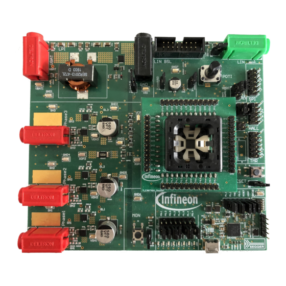
Figure 1 Board concept This board is designed to provide a simple, easy-to-use tool for getting familiar with Infineon's Embedded Power IC TLE987x devices. A socket provides the possibility to test and evaluate all ICs of the TLE987x family. Every pin of the IC is connectable via rows of pin headers. The board is protected against reverse polarity of the input voltage supply. -
Page 6: Interconnects
The three jacks for Phase 1, Phase 2 and Phase 3 provide access to the three half bridges and for driving a brushless motor. uIO Stick connector The uIO bootstrap loader is a 16-pin header (2 × 8) with 2.54 mm pitch. This interface can be used to programming the TLE987x via LIN (see www.infineon.com/uio www.hitex.com/ uio). User Manual v1.0... - Page 7 TLE987x EvalBoard 2 Interconnects N.C. N.C. N.C. N.C. RESET LIN N.C. N.C. N.C. N.C. N.C. N.C. N.C. Figure 3 Pin configuration uIO BSL USB for on-board debugger The on-board connector can be accessed with a micro-USB cable, connected to a PC. Pin header for SWD The 10-pin header (2 ×...
- Page 8 TLE987x EvalBoard 2 Interconnects HALL C HALL B HALL A GND VDDEXT HALL C HALL B HALL A GND VDDEXT Figure 6 Pin configuration Hall sensor interface Pin header for TMR sensor interface The 10-pin header (2 × 5) with 2.54 mm pitch can be used for controlling external TMR sensors. In order to access the TMR sensor interface, the jumpers SINN and SINP have to be set.
-
Page 9: Test Points And Leds
TLE987x EvalBoard 3 Test points and LEDs Test points and LEDs VDDEXT VBAT LEDBAT LEDCOM LED1-8 Figure 8 Test points Test points • 2× VBAT • 1× VS • 1× VCP • 8× GND • 2× SH1, 2× SH2, 2× SH3 •... -
Page 10: Jumper Settings
TLE987x EvalBoard 4 Jumper settings Jumper settings VDDEXT_LED POTI POTI ILoadVSD SIGNAL SUPPLY ILoadVS P0.4 P1.2 SINN SINP Debugger Jumper LEDs & PINs Figure 9 Jumpers Set this jumper to connect RESET button to RESET pin. Open it to disconnect RESET button from RESET pin. Set this jumper to terminate TLE987x in daughter board as LIN master. - Page 11 TLE987x EvalBoard 4 Jumper settings Jumper position 1 Jumper position 2 Figure 10 Jumper position Jumper Position 1 Position 2 POTI SUPPLY VDDEXT VDDP POTI SIGNAL P2.3 P2.4 P0.4 HALL B P1.2 HALL C MISO Figure 11 Jumper position for LEDs and PINs Set jumper as shown in Figure 11 to connect the according PINs and LEDs.
-
Page 12: Communication Interfaces
LIN network, it is sufficient to use the single wire banana interface. The BSL interface programs the device via LIN. For further information about the uIO interface is available at www.infineon.com/uio or www.hitex.com/uio. Debugging Debugging is possible via the on-board debugger that can be connected via an USB cable and the SWD interface;... -
Page 13: Software Toolchain
In addition to the IDE, Infineon provides a solution to speed-up the IC programming, called "ConfigWizard". This tool is designed for code configuration in combination with the IDE. Infineon ConfigWizard can be downloaded via the Infineon Toolbox. The Infineon Toolbox allows to download and update all your Infineon tools. It can be downloaded from www.infineon.com/toolbox. - Page 14 TLE987x EvalBoard 6 Software toolchain Figure 12 Debug and flash configuration ® If the board is connected successfully, the Arm IDCODE will be visible in the SW Device Window. If the connection fails, "Connect & Reset Options" and "Port" window has to be checked. User Manual v1.0 2020-07-30...
-
Page 15: Technical Data
TLE987x EvalBoard 7 Technical data Technical data Table 2 Technical data Voltage supply max. 28 V Motor current max. 30 A Pin ports User Manual v1.0 2020-07-30... -
Page 16: Optional Additional Placements
TLE987x EvalBoard 8 Optional additional placements Optional additional placements CGDLS1 CGSLS1 RSBLS1 CSBLS1 CGSHS1 CGDHS1 CSBHS1 RSBHS1 CXTAL2 CXTAL1 CGDLS1 CGSLS1 RSBLS1 CSBLS1 CGSHS1 CGDHS1 CSBHS1 RSBHS1 CGDLS1 CGSLS1 RSBLS1 CSBLS1 CGSHS1 CGDHS1 CSBHS1 RSBHS1 Figure 13 Additional placements' positions Values for optional additional placements have to be determined depending on application. - Page 17 TLE987x EvalBoard 8 Optional additional placements Table 3 Additional placements (continued) Component Description CSBHS2 Capacitor snubber high-side MOSFET phase 2 CGDHS2 Gate-drain capacitor high-side MOSFET phase 2 CGSHS2 Gate-source capacitor high-side MOSFET phase 2 RSBLS2 Resistance snubber low-side MOSFET phase 2 CSBLS2 Capacitor snubber low-side MOSFET phase 2 CGDLS2...
-
Page 18: Schematics And Layout Baseboard
TLE987x EvalBoard 9 Schematics and layout baseboard Schematics and layout baseboard Schematics baseboard Figure 14 Schematics Sheet 1 User Manual v1.0 2020-07-30... - Page 19 TLE987x EvalBoard 9 Schematics and layout baseboard Figure 15 Schematics Sheet 2 User Manual v1.0 2020-07-30...
- Page 20 TLE987x EvalBoard 9 Schematics and layout baseboard Figure 16 Schematics Sheet 3 User Manual v1.0 2020-07-30...
- Page 21 TLE987x EvalBoard 9 Schematics and layout baseboard Figure 17 Schematics Sheet 4 User Manual v1.0 2020-07-30...
- Page 22 TLE987x EvalBoard 9 Schematics and layout baseboard Figure 18 Schematics Sheet 5 User Manual v1.0 2020-07-30...
- Page 23 TLE987x EvalBoard 9 Schematics and layout baseboard Figure 19 Schematics Sheet 6 User Manual v1.0 2020-07-30...
- Page 24 TLE987x EvalBoard 9 Schematics and layout baseboard Figure 20 Schematics Sheet 7 User Manual v1.0 2020-07-30...
- Page 25 TLE987x EvalBoard 9 Schematics and layout baseboard Figure 21 Schematics Sheet 8 User Manual v1.0 2020-07-30...
- Page 26 TLE987x EvalBoard 9 Schematics and layout baseboard Figure 22 Schematics Sheet 9 User Manual v1.0 2020-07-30...
- Page 27 TLE987x EvalBoard 9 Schematics and layout baseboard Figure 23 Schematics Sheet 10 User Manual v1.0 2020-07-30...
-
Page 28: Layout Baseboard
TLE987x EvalBoard 9 Schematics and layout baseboard Layout baseboard Figure 24 Top layer Figure 25 Power layer User Manual v1.0 2020-07-30... - Page 29 TLE987x EvalBoard 9 Schematics and layout baseboard Figure 26 Ground layer Figure 27 Bottom layer User Manual v1.0 2020-07-30...
-
Page 30: Schematics And Layout Vqfn Socket
TLE987x EvalBoard 10 Schematics and layout VQFN socket Schematics and layout VQFN socket 10.1 Schematics VQFN socket Figure 28 Schematics VQFN socket User Manual v1.0 2020-07-30... -
Page 31: Layout Vqfn Socket
TLE987x EvalBoard 10 Schematics and layout VQFN socket 10.2 Layout VQFN socket Figure 29 Top layer VQFN socket Figure 30 Bottom layer VQFN socket (mirrored) User Manual v1.0 2020-07-30... -
Page 32: Schematics And Layout Tqfp Socket
TLE987x EvalBoard 11 Schematics and layout TQFP socket Schematics and layout TQFP socket 11.1 Schematics TQFP socket Figure 31 Schematics TQFP socket User Manual v1.0 2020-07-30... -
Page 33: Layout Tqfp Socket
TLE987x EvalBoard 11 Schematics and layout TQFP socket 11.2 Layout TQFP socket Figure 32 Top layer TQFP socket Figure 33 Bottom layer TQFP socket (mirrored) User Manual v1.0 2020-07-30... -
Page 34: Revision History
TLE987x EvalBoard 12 Revision history Revision history Revision Date Changes v1.0 2020-07-30 Initial creation. User Manual v1.0 2020-07-30... -
Page 35: Disclaimer
Infineon Technologies, All Rights Reserved. any kind, including without limitation warranties of Infineon Technologies’ products may not be used in non-infringement of intellectual property rights of any any applications where a failure of the product or third party.
Need help?
Do you have a question about the TLE987 Series and is the answer not in the manual?
Questions and answers