
Related Manuals for Mitsubishi Electric CLIMAVENETA BRAN2 0021M


Summary of Contents for Mitsubishi Electric CLIMAVENETA BRAN2 0021M
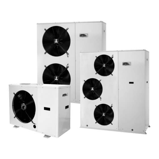
- Page 1 INSTALLATION, USER AND MAINTENANCE MANUAL Air/water chillers and heat pumps with axial-flow fans with and without pump assemblies BRAT2 0021÷0121 BRAN2 0021÷0121...
-
Page 2: Table Of Contents
INDICE INDEX U I A General warnings Checking and starting up the unit U I A Waiver of liability LED and display U I A Fundamental safety rules Displaying alarms Receiving, handling and installing the Peak limiter alarm signals product Operating characteristics Characteristics Shutting down for long periods... -
Page 3: U I A General Warnings
GENERAL WARNINGS U I A These appliances have been designed to chill and/or The documents supplied with the unit must be consigned heat water and must be used in applications compatible to the owner who should keep them carefully for future con- with their performance characteristics;... -
Page 4: I A Receiving, Handling And Installing The
RECEIVING, HANDLING AND INSTALLING THE PRODUCT The chillers are supplied accompanied by: • To avoid the slings damaging the unit, place protection - installation, user and maintenance manual; between the slings and the unit. - CE declaration; Position the unit in the site indicated by the customer. Place either a layer of rubber (min. -
Page 5: I A Characteristics
CHARACTERISTICS 0021÷0031 The BRAT(N)2 appliances are air-water units operating on R-410A and refrigerant are suitable for outdoor installation. The units are CE marked, as established by the EU direc- tives, including the latest amendments, and the correspond- ing approximated national legislation. They are factory tested and on site installation is limited to water and electrical connections. -
Page 6: Dimensioned Drawings
DIMENSIONED DRAWINGS 0021M-T 0025M-T 0031M-T 0041M-T 0051T 0061T 0071T 0091T 0101T 0121T Dimension 1450 1450 1450 1450 1240 1240 1390 1200 1200 1700 1700 1477 1477 1477 1477 0021M-T 0025M-T 0031M-T 0041M-T 0051T 0061T 0071T 0091T 0101T 0121T Weight distribution BRAT2 Total in operation 0021M-T 0025M-T 0031M-T 0041M-T 0051T 0061T... - Page 7 Minimum system water content Size 0021M-T 0025M-T 0031M-T 0041M-T 0051T 0061T 0071T 0091T 0101T 0121T Minimum water content BRAT2 Minimum water content BRAN2 Expansion vessel size Size 0021M-T 0025M-T 0031M-T 0041M-T 0051T 0061T 0071T 0091T 0101T 0121T Expansion vessel BRAT2 Expansion vessel BRAN2 Safety valve calibration Size...
- Page 8 System water circuit connection diagram, BRAN2 version WITH HYDRONIC KIT FACTORY CONNECTED INSTALLER CONNECTIONS PRESSURE GAUGE UTILITY VIBRATION-ISOLATING JOINT OUTLET SHUT-OFF VALVE CALIBRATING VALVE FLOW SWITCH THERMOMETER CIRCULATOR PUMP SAFETY VALVE EXPANSION VESSEL 10 MESH FILTER 11 FILL/TOP-UP 12 TEMPERATURE PROBE 13 DIFFERENTIAL PRESSURE SWITCH 14 DRAIN/CHEMICAL WASHING...
- Page 9 Fouling factors Evaporator Fouling factors °C/W) The performance data given refer to conditions with clean evaporator plates (fouling factor = 1). 4,4 x 10 For different fouling factors, multiply the figures in the perfor- 0,86 x 10 0,96 0,99 0,99 mance tables by the coefficient given in the following table.
-
Page 10: I A Electrical Connections
FILLING THE SYSTEM The system must be filled to a pressure of between 1 - Before filling, check that the system drain valve is closed. and 2 bars. - Open all system and terminal air vents. It is recommended that this operation be repeated after - Open system shut off valves. - Page 11 ELECTRICAL DATA, BRAT2 AND BRAN2 WITHOUT HYDRONIC KIT Power supply Maximum values Fuses (5x20T 250V) Size (V-Ph-Hz) FLA [A] FLI [kW] SA [A] SA LIM [A] BRAT2 - BRAN2 0021 230-1N-50 16,6 61,6 27,6 1,25A BRAT2 - BRAN2 0025 230-1N-50 19,6 82,6 37,6...
-
Page 12: I A Mains Power Supply Connections
MAINS POWER SUPPLY CONNECTIONS • Before connecting the unit to the power supply, makes • Use cable gland A for the main electrical power cable and sure that switch QF1 is open, suitably padlocked and cable gland B for other external cables to be connected by marked. - Page 13 OUTSIDE AIR PROBE (BT3) (Accessory) The outside air probe allows the system water temperature set point to be compensated during heating or cooling opera- tion. Installation instructions The outside air probe must be installed: • outside of the home • not in direct sunlight, away from flue gas discharges, air outlets, or doors and windows.
-
Page 14: I A General Technical Data
GENERAL TECHNICAL DATA BRAT2 without hydronic kit 0021 0025 0031 0041 0021 0025 0031 0041 0051 0061 0071 0091 0101 0121 Cooling capacity [kW] 7,71 9,50 11,5 15,0 7,70 11,64 15,7 17,9 20,5 25,1 28,4 35,1 40,6 Power consumption [kW] 2,18 2,71 3,73... - Page 15 GENERAL TECHNICAL DATA BRAN2 without hydronic kit 0021 0025 0031 0041 0021 0025 0031 0041 0051 0061 0071 0091 0101 0121 Heating capacity [kW] 6,76 8,37 10,5 12,9 6,73 10,00 13,4 14,8 17,3 21,5 24,7 29,7 35,9 Power consumption [kW] 2,31 2,93 3,57...
-
Page 16: U I A Operating Limits
OPERATING LIMITS U I A COOLING OPERATION WITH WATER-GLYCOL MIX Water outlet temperature at evaporator [°C] Operating range in COOLING Water temperature head min-max= 3-8 K Water circuit pressure min-max= 1-6 bars Max storage temperature= 63°C Maximum percentage of glycol= 40% As standard, the unit is manufactured with operating parameters allowing water produced at the evaporator down to +5°C. -
Page 17: I A Pressure Drop And Pressure Head Available
PRESSURE DROP AND PRESSURE HEAD AVAILABLE TO SYSTEM U I A SYSTEM HEAT EXCHANGER PRESSURE DROP, UNIT WITHOUT HYDRONIC KIT System heat exchanger pressure drop 0021 0025 0041 0031 0051 0061 Water flow-rate [m System heat exchanger pressure drop 0071 0091 0101 0121... - Page 18 PRESSURE DROP AND PRESSURE HEAD AVAILABLE TO SYSTEM U I A AVAILABLE PRESSURE HEAD, UNIT WITH HYDRONIC KIT Presión estática útil 0041 0051 0061 Water flow-rate [m Available pressure head 0121 0071 0091 0101 Water flow-rate [m The pressure head refers to the value available to the system. The pump installed on the unit, if the “hydronic kit”...
-
Page 19: A Checking And Starting Up The Unit
CHECKING AND STARTING UP THE UNIT PREPARING FOR FIRST START UP or restarting STARTING UP FOR THE FIRST TIME (after two hours) after shutting down for long periods. The unit must be started up for the first time by the Techni- Before starting the chiller: cal Service. -
Page 20: Aled And Display
LEDS AND DISPLAY 1 STATUS AND OPERATING MODE LEDS 2 VALUE AND UNIT OF MEASURE LEDS Alarm Clock Heating Degrees centigrade Cooling Pressure (Bar) Standby Menu (ABC) Defrost 3 UTILITY LEDS Compressor Fans System pump Frost protection heater system heat exchanger BRAT2 - BRAN2 EN... - Page 21 SETTING THE CLOCK The HSW15 controller is fitted with a clock for managing time bands to control specific events. Follow the procedure shown below to set the hours, minutes and date. To set the clock of the unit, starting from the main display, press the set button.
- Page 22 ... press the set button. To exit the clock setting menu press the esc button until returning to the main display. BRAT2 - BRAN2 EN...
- Page 23 SCHEDULER SETTING The HSW15 controller can manage the unit based o the time and the day of the week. The controller features four time bands in three profiles that can be combined, when programming, with the days of the week. The profile defines the behaviour of the unit over a 24 hour period.
- Page 24 SELECTING THE OPERATING MODE SETTING THE SET POINTS There are three different modes: As an example, the Set Point in COOL mode will be • Standby mode (StbY) changed from 12.0 degrees centigrade to 12.5 degrees • Cooling mode (COOL) centigrade.
- Page 25 SETTING THE PARAMETERS Accessing the PASS directory (from the main display, press- ing the esc and set buttons together [esc+set] and scrolling to the directory with up / down) and setting the PASS accesses the parameters visible for the password entered. The instrument will display the current set point (in this case 12.0 degrees centigrade).
- Page 26 The first directory displayed by the instrument will be the CF When having selected the value, press the set button. ** directory (configuration). To exit the display and return to the previous level, press To set the individual CF parameters, simply press set again. esc.
- Page 27 DISPLAYING AND RESETTING COMPRESSOR / PUMP HOURS Example of displaying and resetting (tens) the Pump operat- The tens of operating hours are equal to 2. ing hours. (The hours are expressed in tens: 2 indicates 20 operating From the main display, press the set button. hours).
-
Page 28: I A Displaying Alarms
LIST OF ACCESSIBLE PARAMETERS Directory label Parameters Parameters for: CF00... CF77 Configuration UI00... UI18 User interface tr00... tr20 Temperature control St00... St04 Operating status CP00... CP10 Compressor Primary pump PI00... PI24 Primary water circuit pump Fans FE00... FE30 Fans Electric HI00... -
Page 29: I A Peak Limiter Alarm Signals
FAULT CAUSE SOLUTION Values display indication Faulty BT2 system water outlet sensor Check electrical connections Er61 (automatic reset) Replace component Check electrical connection (see unit wiring dia- Display indication Pressure transducer malfunction grams) Er75 Replace component Check operating pressure Display indication Compressor maintenance interval Check condition of the compressor Er81... -
Page 30: I A Operating Characteristics
OPERATING CHARACTERISTICS Cooling set point WATER FLOW ALARM (factory setting) = 12°C, Hysteresis = 3°C. The microprocessor provides for the management of a The compressor starts at outlet water temperatures above water flow alarm controlled by a differential pressure switch 12°C+3°C (15°C). - Page 31 OPERATING CHARACTERISTICS SYSTEM WATER SET POINT COMPENSATION BASED ON THE OUTSIDE TEMPERATURE Set point compensation based on the outside temperature must be enabled by setting a parameter, see the table. Outside air temperature probe to be purchased as an accessory, not supplied with the unit. System water set point compensation in COOLING mode based on the outside temperature Water temperature set point 15°C...
-
Page 32: A Shutting Down For Long Periods
SHUTTING DOWN FOR LONG PERIODS After deactivating the chiller: If the mains switch is turned to “off” for more than four - Make sure the remote switch SA1 (if featured) is off. hours, after turning it on and before reactivating the unit, - Make sure the remote keypad (if featured) shows “OFF”. -
Page 33: I A Troubleshooting
TROUBLESHOOTING U I A FAULT CAUSE SOLUTION Check presence of voltage The unit doesn’t start Power failure Check safety systems upstream of the appliance Switch QF1 in OFF position Remote switch (if featured) in OFF position Control panel in standby Switch ON Main switch QS1 in OFF Compressor circuit breaker OFF... - Page 34 FAULT CAUSE SOLUTION High discharge pressure High outside water temperature Check (greater than 32 bars)* High utility water inlet temperature Insufficient water flow-rate in outside heat exchanger Check pump operation Faulty operation of outside heat exchanger control Check (pressure regulating valves) Air in water circuit Vent Excessive refrigerant charge...
-
Page 35: U I A Useful Information
USEFUL INFORMATION U I A For information on technical assistance and obtaining spare parts, contact: CLIMAVENETA S.P.A. AFTER SALES DEPARTMENT - RESIDENTIAL BUSINESS Via Duca d’Aosta 121 - 31031 Mignagola di Carbonera (TV) ITALY Tel: +39.0424.509500 Fax: +39.0424.509563 www.climaveneta.com - info@climaveneta.com BRAT2 - BRAN2 EN...