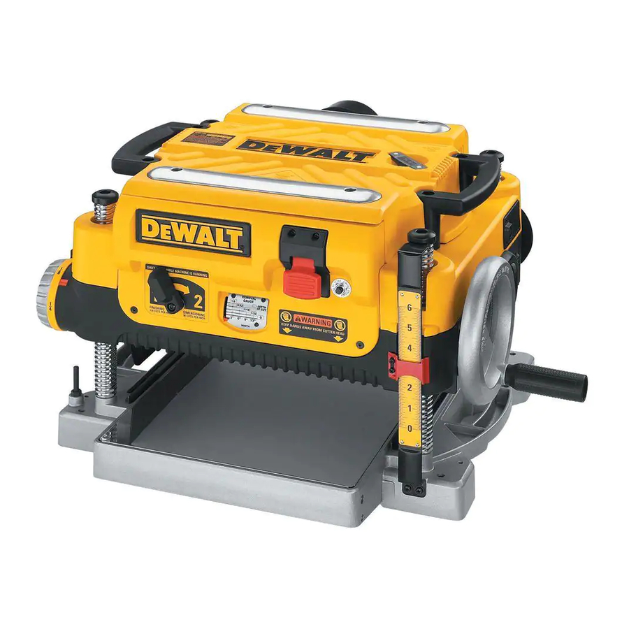
DEWALT DW735 Planer Manual
- User manual ,
- Instruction manual (56 pages) ,
- Original instructions manual (53 pages)
Advertisement
- 1 Technical Data
- 2 Definitions: Safety Guidelines
- 3 GENERAL POWER TOOL SAFETY WARNINGS
- 4 Electrical Safety
- 5 Package Contents
- 6 Description
- 7 ASSEMBLY AND ADJUSTMENTS
- 8 OPERATION
- 9 MAINTENANCE
- 10 Protecting the Environment
- 11 Troubleshooting Guide
- 12 Videos
- 13 Documents / Resources
Technical Data
| Voltage | VAC | 230–240 |
| Power input | W | 1800 |
| No-load/rated speed | min-1 | 10000 |
| Operating / Resting time | min | 1/3 |
| Feed Speed | m/min (ft./min) | 4.3 (14) or 7.0 (26) |
| Cutting height (max.) | mm (") | 152 (6) |
| Cutting width (max.) | mm (") | 330 (13) |
| Max. cutting depth for max. board width of 152 mm (6") | mm (") | 3 (1/8) |
| Weight | kg | 42.6 |
| LPA (emission sound pressure level) | dB(A) | 95 |
| KPA (sound pressure uncertainty) | dB(A) | 3.3 |
| LWA (sound power level) | dB(A) | 108 |
| KWA (sound power uncertainty) | dB(A) | 3.7 |
The vibration and/or noise emission level given in this information sheet has been measured in accordance with a standardised test given in EN60745 and may be used to compare one tool with another. It may be used for a preliminary assessment of exposure.

The declared vibration and/or noise emission level represents the main applications of the tool. However if the tool is used for different applications, with different accessories or poorly maintained, the vibration and/or noise emission may differ. This may significantly increase the exposure level over the total working period.
An estimation of the level of exposure to vibration and/or noise should also take into account the times when the tool is switched off or when it is running but not actually doing the job. This may significantly reduce the exposure level over the total working period.
Identify additional safety measures to protect the operator from the effects of vibration and/or noise such as: maintain the tool and the accessories, keep the hands warm (relevant for vibration), organisation of work patterns.
![]() To reduce the risk of injury, read the instruction manual.
To reduce the risk of injury, read the instruction manual.
Definitions: Safety Guidelines
The definitions below describe the level of severity for each signal word. Please read the manual and pay attention to these symbols.

Indicates an imminently hazardous situation which, if not avoided, will result in death or serious injury.
Indicates a potentially hazardous situation which, if not avoided, could result in death or serious injury.

Indicates a potentially hazardous situation which, if not avoided, may result in minor or moderate injury.
NOTICE: Indicates a practice not related to personal injury which, if not avoided, may result in property damage.
 Denotes risk of electric shock.
 Denotes risk of fire.
GENERAL POWER TOOL SAFETY WARNINGS
Read all safety warnings, instructions, illustrations and specifications provided with this power tool. Failure to follow all instructions listed below may result in electric shock, fire and/or serious injury.
SAVE ALL WARNINGS AND INSTRUCTIONS FOR FUTURE REFERENCE.
The term "power tool" in the warnings refers to your mainsoperated (corded) power tool or battery-operated (cordless) power tool.
Work Area Safety
- Keep work area clean and well lit. Cluttered or dark areas invite accidents.
- Do not operate power tools in explosive atmospheres, such as in the presence of flammable liquids, gases or dust. Power tools create sparks which may ignite the dust or fumes.
- Keep children and bystanders away while operating a power tool. Distractions can cause you to lose control.
Electrical Safety
- Power tool plugs must match the outlet. Never modify the plug in any way. Do not use any adapter plugs with earthed (grounded) power tools. Unmodified plugs and matching outlets will reduce risk of electric shock.
- Avoid body contact with earthed or grounded surfaces, such as pipes, radiators, ranges and refrigerators. There is an increased risk of electric shock if your body is earthed or grounded.
- Do not expose power tools to rain or wet conditions. Water entering a power tool will increase the risk of electric shock.
- Do not abuse the cord. Never use the cord for carrying, pulling or unplugging the power tool. Keep cord away from heat, oil, sharp edges or moving parts. Damaged or entangled cords increase the risk of electric shock.
- When operating a power tool outdoors, use an extension cord suitable for outdoor use. Use of a cord suitable for outdoor use reduces the risk of electric shock.
- If operating a power tool in a damp location is unavoidable, use a residual current device (RCD) protected supply. Use of an RCD reduces the risk of electric shock.
Personal Safety
- Stay alert, watch what you are doing and use common sense when operating a power tool. Do not use a power tool while you are tired or under the influence of drugs, alcohol or medication. A moment of inattention while operating power tools may result in serious personal injury.
- Use personal protective equipment. Always wear eye protection. Protective equipment such as a dust mask, non-skid safety shoes, hard hat or hearing protection used for appropriate conditions will reduce personal injuries.
- Prevent unintentional starting. Ensure the switch is in the off-position before connecting to power source and/or battery pack, picking up or carrying the tool. Carrying power tools with your finger on the switch or energising power tools that have the switch on invites accidents.
- Remove any adjusting key or wrench before turning the power tool on. A wrench or a key left attached to a rotating part of the power tool may result in personal injury.
- Do not overreach. Keep proper footing and balance at all times. This enables better control of the power tool in unexpected situations.
- Dress properly. Do not wear loose clothing or jewellery. Keep your hair and clothing away from moving parts. Loose clothes, jewellery or long hair can be caught in moving parts.
- If devices are provided for the connection of dust extraction and collection facilities, ensure these are connected and properly used. Use of dust collection can reduce dust-related hazards.
- Do not let familiarity gained from frequent use of tools allow you to become complacent and ignore tool safety principles. A careless action can cause severe injury within a fraction of a second.
Power Tool Use and Care
- Do not force the power tool. Use the correct power tool for your application. The correct power tool will do the job better and safer at the rate for which it was designed.
- Do not use the power tool if the switch does not turn it on and off. Any power tool that cannot be controlled with the switch is dangerous and must be repaired.
- Disconnect the plug from the power source and/ or remove the battery pack, if detachable, from the power tool before making any adjustments, changing accessories, or storing power tools. Such preventive safety measures reduce the risk of starting the power tool accidentally.
- Store idle power tools out of the reach of children and do not allow persons unfamiliar with the power tool or these instructions to operate the power tool. Power tools are dangerous in the hands of untrained users.
- Maintain power tools and accessories. Check for misalignment or binding of moving parts, breakage of parts and any other condition that may affect the power tool's operation. If damaged, have the power tool repaired before use. Many accidents are caused by poorly maintained power tools.
- Keep cutting tools sharp and clean. Properly maintained cutting tools with sharp cutting edges are less likely to bind and are easier to control.
- Use the power tool, accessories and tool bits etc. in accordance with these instructions, taking into account the working conditions and the work to be performed. Use of the power tool for operations different from those intended could result in a hazardous situation.
- Keep handles and grasping surfaces dry, clean and free from oil and grease. Slippery handles and grasping surfaces do not allow for safe handling and control of the tool in unexpected situations.
Service
- Have your power tool serviced by a qualified repair person using only identical replacement parts. This will ensure that the safety of the power tool is maintained.
Additional Specific Safety Rules for Planers
- To reduce the risk of injury, user must read and understand instruction manual before operating planer.
- Always wear eye protection and dust mask if necessary.
- Keep hands away from the underside of the cutter head carriage.
- Never clear clogs, make cutter knife replacement, or any other repairs/adjustments with unit plugged in.
- Make certain that the switch is in the OFF position before connecting plug to a power source.
- To prevent unexpected "turn on" of the tool after power is disrupted, turn the switch OFF before restoring power.
- Be sure that the cutter knives are mounted as described in the instruction manual and check that all bolts are firmly tightened before connecting unit to power source.
- To avoid injury, never rotate the cutter block directly with your hands.
- Keep guards in place and in good working order.
- Stay alert – never operate the unit when tired or under the influence of drugs, alcohol, or medication.
- Do not use in dangerous environments. Do not use near flammable substances, in damp or wet locations, or expose to rain.
- Never plane material which is shorter than 304.8 mm (12").
- Exhaust chute: remove shavings with brush or vacuum after power has been shut off and cutter head has stopped rotating.
- Always locate planer with proper clearance on the outfeed side of the unit to prevent pinching or binding of the workpiece against any obstacle.
- Clean out your tool often, especially after heavy use. Dust and grit containing metal particles often accumulate on interior surfaces and could create a risk of serious injury, electric shock or electrocution.
- ALWAYS WEAR SAFETY GLASSES.
![]()
For your own safety, it is recommended that two people carry this machine or serious injury could result. - Air vents often cover moving parts and should be avoided. Loose clothes, jewellery or long hair can be caught in moving parts.
![]()
We recommend the use of a residual current device with a residual current rating of 30mA or less.
![]()
Some dust created by power sanding, sawing, grinding, drilling, and other construction activities contains chemicals known to cause cancer, birth defects or other reproductive harm. Some examples of these chemicals are:- lead from lead-based paints,
- crystalline silica from bricks and cement and other masonry products, and
- arsenic and chromium from chemicallytreated lumber.
Your risk from these exposures varies, depending on how often you do this type of work. To reduce your exposure to these chemicals: work in a well ventilated area, and work with approved safety equipment, such as those dust masks that are specially designed to filter out microscopic particles.
- Avoid prolonged contact with dust from power sanding, sawing, grinding, drilling, and other construction activities. Wear protective clothing and wash exposed areas with soap and water. Allowing dust to get into your mouth, eyes, or lay on the skin may promote absorption of harmful chemicals.
Electrical Safety
The electric motor has been designed for one voltage only. Always check that the power supply corresponds to the voltage on the rating plate.

Your DeWALT tool is double insulated in accordance with EN60745; therefore no earth wire is required.
If the supply cord is damaged, it must be replaced only by DeWALT or an authorised service organisation.
Mains Plug Replacement (U.K. & Ireland Only)
If a new mains plug needs to be fitted:
- Safely dispose of the old plug.
- Connect the brown lead to the live terminal in the plug.
- Connect the blue lead to the neutral terminal.
No connection is to be made to the earth terminal.
Follow the fitting instructions supplied with good quality plugs. Recommended fuse: 13 A.
Using an Extension Cable
If an extension cable is required, use an approved 3–core extension cable suitable for the power input of this tool (see Technical Data).The minimum conductor size is 1.5 mm²; the maximum length is 30 m.
When using a cable reel, always unwind the cable completely.
Package Contents
The package contains:
| 1 | Planer |
| 1 | Round dust port |
| 1 | T-wrench (located in the top cover of the unit) |
| 1 | Depth adjustment crank handle |
| 1 | Hex screw for crank handle |
| 1 | Instruction manual |
- Check for damage to the tool, parts or accessories which may have occurred during transport.
- Take the time to thoroughly read and understand this manual prior to operation.
Description

Fig. A
Never modify the power tool or any part of it. Damage or personal injury could result.
- Planer
- Side carrying handles
- Base handles
- Bench mounting holes
- Crank handle
- On/off switch
Intended Use
This planer is designed for professional wood working.
DO NOT use under wet conditions or in the presence of flammable liquids or gases. This planer is a professional power tool.
DO NOT let children come into contact with the tool. Supervision is required when inexperienced operators use this tool.
- Young children and the infirm. This appliance is not intended for use by young children or infirm persons without supervision.
- This product is not intended for use by persons (including children) suffering from diminished physical, sensory or mental abilities; lack of experience, knowledge or skills unless they are supervised by a person responsible for their safety. Children should never be left alone with this product.
ASSEMBLY AND ADJUSTMENTS
To reduce the risk of serious personal injury, turn tool off and disconnect tool from power source before making any adjustments or removing/ installing attachments or accessories. An accidental start-up can cause injury.
Do not remove guards ( , Fig. B). Serious injury could result.

Fig. B
Transporting the Planer
(Fig. A)
For your own safety, it is recommended that two people carry this machine or serious injury could result.
When moving your planer, carry it either by the side carrying handles  or by the handles
  at the base of the planer.
Bench Mounting
(Fig. A)
To facilitate bench mounting, two different sized holes  are provided on the four corners of your planer. If mounting the planer with bolts, use the larger holes. If mounting the planer with nails or screws, use the smaller holes. It is not necessary to use both sets of holes.
Always mount your planer firmly to prevent movement. To enhance the tool's portability, it can be mounted to a piece of 12.7 mm or thicker plywood which can then be clamped to your work support or moved to other job sites and reclamped.
NOTE: If you elect to mount your planer onto a piece of plywood, make sure that the mounting screws don't protrude from the bottom of the wood. The plywood must sit flush on the work support.
The mounting surface should not be warped or otherwise uneven.
To Attach the Depth Adjustment Crank Handle

Fig. C
- Remove the screw located in the crank handle shaft.
- Insert the crank handle
![]() over the shaft.
over the shaft. - Secure in place with the screw and T-wrench
![]() provided.
provided.
 over the shaft.
 provided.
 Dust Ejection Ports

Fig. D
Your planer comes with a dust ejection port. The round port  as shown in Figure. F is for use with a 100 mm dust collector hose.
To Set Up Dust Ejection
(Fig. D)
Do not operate your planer without the dust ejection port locked into place. Do not insert anything into the dust ejection chute unless the planer is unplugged and you are clearing a clog or obstruction in the unit. Do not get your face or eyes near the dust ejection port when the planer is in operation. Serious injury could result.
Chips are ejected at significant velocity. Keep hands and face clear of dust ejection port.
- Select the port
![]() .
. - Depress the lock button
![]() on the chip ejection chute
on the chip ejection chute ![]() .
. - Slide the notches in the dust port over the pins on the chip ejection chute.
- Rotate the port until the button engages the dust ejection chute and locks in place.
 on the chip ejection chute
  .
.To Remove the Dust Ejection Port
(Fig. D)
- Use the T-wrench to depress the lock button
![]() on the dust chute.
on the dust chute. - Twist the port until the pins are disengaged from the notches on the port.
- Pull the dust ejection port off of the dust chute.
Depth Adjustment

Fig. E
Depth Adjustment Scale
(Fig. E)
The depth adjustment scale  , located on the right front of your planer, indicates the finished thickness of your workpiece. One rotation of the depth adjustment crank is equal to 1.6 mm, half rotation is equal to 0.8 mm, etc.
Depth Adjustment Crank
Turning the crank clockwise lowers the cutterhead. Turning the crank counterclockwise raises the cutterhead.
Turret Stop

Fig. F
Your planer is equipped with a turret stop  for planing multiple boards to the same pre-set depth. Stops are set at 3 mm, 6.5 mm, 12.7 mm, 319 mm, 25.5 mm, and 32 mm.
To Set the Minimum Depth to Which the Carriage can Travel with the Turret Stop
- Be sure the carriage is set above 32 mm before trying to set the turret stop.
- Turn the dial on the front left of the planer until the desired thickness setting aligns with the red indicator, then lower the carriage.
- Plane the workpiece at desired increments until the correct final thickness is achieved.
NOTE: Do not use force to crank the carriage below the level that the turret stop indicates. Permanent damage to the height adjust ment system on your planer will result.
OPERATION
Instructions for Use
Always observe the safety instructions and applicable regulations.
To reduce the risk of serious personal injury, turn tool off and disconnect tool from power source before making any adjustments or removing/installing attachments or accessories. An accidental start-up can cause injury.
On/Off Switch

Fig. G
To turn the planer on, lift the switch  up.
up.
The planer locks on automatically. To turn the tool off, press the switch down. A hole  is provided under the switch for insertion of a padlock to lock off the planer.
Speed Selection

Fig. H
NOTE: Only switch speeds when the planer is running.
Your planer has the ability to feed material at two different speeds. The two-speed feature  was designed to improve efficiency when planing and to provide the best possible surface finish to a variety of materials.
To remove material thickness more quickly, set the unit at speed "2". This setting delivers 96 cuts per inch to the material.
For finishing, set the unit to speed "1". Speed "1" is ideal for ensuring the finest finish on the last pass before your final thickness is achieved.
NOTE: When planing particularly hard or figured species of wood, speed "1" is recommended. The slower feed rate will reduce knife wear and tear-out by delivering 179 cuts per inch to the material.
Material Removal Gauge

Fig. I
Your planer is equipped with a material removal gauge  . It is used to indicate the amount of wood that will be removed in one pass with the carriage set at its current height.
To Use the Material Removal Gauge
- Slide approximately 75 mm of your ma terial under the middle of the carriage.
- Be sure the wood is lying flat against the base of the planer. If the material is inserted at an angle, the reading may be inaccurate.
- Crank the carriage down on the ma terial until the material removal bar engages the wood. You will see the red arrow begin to move up the scale indicating the amount of material to be removed with the carriage at that height.
- Adjust the carriage height until the desired depth of cut appears on the gauge.
- Pull the material out from under the carriage.
- Turn the unit on and feed your material into the cutterhead.
NOTE: Do not exceed the recommended depth of cut for various widths of material recommended on the material removal gauge.
DO NOT switch the unit on with the material positioned under the carriage. Serious injury could result.
Planing Basics
Proper Planing Technique
DO NOT turn the unit on with the material already inserted under the carriage. Wait until the rollers and cutterhead are up to full speed before feeding your material into the machine.
To Plane Your Material
- Lower the carriage to the desired height for your first pass.
- Turn the unit on and feed the material into the feed rollers.
- Examine the finished cut and adjust the carriage to the appropriate height for your next pass.
NOTE: Flip the board back and forth between each pass. See the Troubleshooting Guide, for additional information. For best results, plane both sides of the workpiece to reach a desired thickness. For example, if you need to remove 3 mm from your workpiece, remove 1.6 mm from each side. This not only allows the workpiece to dry with an even moisture content, it also produces finer cuts.
Plane only wood that is free from foreign objects, with no loose knots and as few tight knots as possible. Do not plane wood that is severely warped, twisted, knotted or bowed.
Do not place your body between the rear of the planer and a stationary object while material is feeding. Serious injury could result.
Minimum/Maximum Width/Height/Depth
NOTE: Always plane in the direction of the grain. Support the workpiece adequately at all times. Planing material less than 19 mm wide is not recommended. If you must plane narrow material, group several pieces together and plane them as one wide workpiece whenever possible.
The maximum depth of cut your planer can take in one pass is 3 mm [on material less than 152 mm wide]. Never attempt to modify your planer to take a deeper cut. Follow the recommended depth/width of cut guidelines shown in Table A for best results.

TABLE A
Snipe
Snipe is a depression made when an unsupported end of your material drops toward the floor, causing the opposite end to lift up into the cutterhead.
To Avoid Snipe
Feed the workpiece into the planer so it is level and remains flat against the base at all times.
Keep the workpiece level throughout planing operation by receiving or "catching" it from the rear of the planer.
If you are planing material that is especially long, the use of additional material support is recommended.
Twisted, Cupped and Bowed Wood

Fig. J
If both sides of your material are very rough or if the material is cupped, bowed or twisted, your planer may not produce the desired result. Ideally, you should have at least one level face/ surface on your material before you plane. Your thickness planer will work best with material that has been run through a jointer to produce one flat surface. If you do not have at least one flat surface or a jointer, see the following recommendations.
To Plane Twisted Wood

Fig. K
Twisted wood may jam your thickness planer. If a jam occurs, turn the power off, disconnect the power supply and raise the carriage to release the material from the cutterhead.
If your material is only slightly twisted: Plane both sides alternating from one to the other until the desired thickness is reached.
To Plane Cupped Wood

Fig. L
To obtain the best possible results with cupped wood: Rip the material down the middle and plane it as two separate pieces.
Ripping the material reduces the severity of the cup and allows the machine to deliver better results. Understand that you will have to remove more material on cupped wood to achieve the desired thickness than you would on a normal board.
If Ripping the Material is Not an Option
Plane one side of the material until flat, then plane the opposite side until it is also flat.
NOTE: Do not flip the board back and forth between each pass if wood is cupped.
To Plane Bowed Wood

Fig. M
The feed rollers and cutterhead in your planer will push the bow out of the material as it feeds. However, when the material exits the planer, the pressure of the rollers and cutterhead will release allowing the wood to spring back into a bowed formation. To properly remove the bow, use a jointer. BOWED WOOD WILL BE FLATTENED BY FEED ROLLERS AND CUTTERHEAD BUT BOW WILL RETURN AFTER WOOD IS PLANED (Fig. M)
MAINTENANCE
Your power tool has been designed to operate over a long period of time with a minimum of maintenance. Continuous satisfactory operation depends upon proper tool care and regular cleaning.
To reduce the risk of serious personal injury, turn tool off and disconnect tool from power source before making any adjustments or removing/installing attachments or accessories. An accidental start-up can cause injury.
Periodic Maintenance
- Routinely check the tool for damage or broken parts.
- Clean the top cover, dust shroud and all accessible areas of the unit of dust and wood debris that have collected in from planeing.
- Wipe off infeed and outfeed rollers.
- Clean base table. Light waxing will help wood material pass through the planer.
- Evaluate blade sharpness condition. Replace as necessary.
- Gauge Calibration, check thickness gauge calibration and turret stop calibration.
- Check brushes for wear and replace as necessary.
Changing or Rotating the Planer Knives
To reduce the risk of serious personal injury, disconnect the planer from the power source before attempting to change or access the knives. An accidental start-up can cause injury.
To Change Planer Knives (Fig. N–S)
- Use the T-wrench to remove the four screws in the top of the planer.
- Lift the top off (Fig. N) and place it aside.
![]()
Fig. N - Remove the three wing nuts that seal the dust shroud over the cutterhead.
- Rotate the dust shroud up so the round connection that locks onto the fan housing is in the open position (Fig. O).

Fig. O - Push the dust shroud to the left so it disengages from the fan housing.
- Take the dust shroud out of the unit (Fig. P) and set it aside.
![]()
Fig. P - The cutterhead is now exposed. If the eight screws in the cutterhead clamp are not visible, use a piece of scrap wood to carefully rotate the cutterhead (Fig. Q) until the screws are accessible and the cutterhead lock lever
![]() engages. This will prevent further rotation of the cutterhead as you change the knives.
engages. This will prevent further rotation of the cutterhead as you change the knives.

Fig. Q
![]()
Keep your fingers away from the cutterhead at all times. Use the tool provided to handle the knives. - Use the T-wrench to remove the eight screws on the knife clamp and set them in the small screws bin
![]() on the front panel of the planer (Fig. R).
on the front panel of the planer (Fig. R).

Fig. R - Use the magnets on the top of the T-wrench to attract the knife clamp and lift it off of the cutterhead. One of the knives should now be exposed.
- Use the magnet
![]() on the top of the T-wrench (Fig. Q) to attract the knife. Avoid touching it with your fingers.
on the top of the T-wrench (Fig. Q) to attract the knife. Avoid touching it with your fingers.
![]()
Fig. S


 engages. This will prevent further rotation of the cutterhead as you change the knives.
 on the front panel of the planer (Fig. R).
 on the top of the T-wrench (Fig. Q) to attract the knife. Avoid touching it with your fingers.
NOTE: Before installing the knife, ensure the cutterhead and knife are free of debris, clean if needed.
If Only One Side of the Knife Is Worn
- Rotate the knife around so that the sharp, unused edge hangs over the end of the cutterhead where it will cut the material. Be sure to set the oblong holes in the knife over the pins machined on the cutterhead.
- Reset the knife clamp over the knife. Be sure to align the beveled edge on the clamp with the sharp, cutting edge of the knife. If these are not aligned correctly, the clamp will not secure the knife properly.
- Install the screws into the clamp and tighten sufficiently.
NOTE: Make sure all screws are tightened sufficiently.
To Access the Other Two Knives
- Depress the cutterhead lock lever
![]() as shown in Figure Q.
as shown in Figure Q. - Use the piece of scrap wood to carefully turn the cutterhead until it locks into place revealing another knife clamp.
- Follow the same knife change procedure indicated above.
- Repeat the procedure for the last dull knife.
After Installing New Knives
- Insert the round end of the dust shroud into the fan housing and rotate it down to lock it into place.
- Place the three wing nuts back into the shroud.
- Screw the top cover of the planer back onto the unit.
NOTE: The planer will not operate if the top cover is not placed correctly.
Brush Change
Your planer is equipped with brush caps  that are external to the motor. If your brushes need to be replaced, begin by acquiring a new set from a DeWALT service center or a dealer authorized to service DeWALT products. Use only identical DeWALT brushes.

Fig. T
To Replace the Brushes on your Planer
(Fig. T, U)
- Use the T-wrench to remove the top cover and brush cover screen on the planer.
- Use a flathead screwdriver to unscrew the brush cap located in the right, rear of the unit
![]() .
.

Fig. U - Do the same for the brush cap located on the side of the motor, inside the planer cover.
- Place the new brushes into the brush holders.
- After installing the brushes, replace the top cover and brush cover screen.
- Before using the planer, run the unit for 10 minutes to seat new brushes.
 .
. 
NOTE: If existing brushes do not need replacing, be sure to maintain the same orientation when you reinstall them.
Calibrating the Depth Adjustment Scale

Fig. V
The depth adjustment scale on your planer is set at the factory. However, with extended use, the depth adjustment scale could show an incorrect measurement.
To check the depth adjustment scale, plane a piece of scrap wood, noting the measurement on the depth adjustment scale.
Measure the finished thickness of the workpiece. If the thickness of the workpiece does not match the reading on the depth adjustment scale, loosen the two screws  on the red indicator. Adjust the pointer up or down until its reading matches the finished thickness of the workpiece. Securely re-tighten the screws.
Base Maintenance
Keep the table clean and free from oil, grease, and pitch. Treat the table with paste wax to help maintain its smooth finish.
Circuit Breaker Reset Button

Fig. W
Your planer is equipped with an 18 amp circuit breaker. If your planer becomes overloaded and stops operating, turn off the planer, let the unit sit for 2 minutes and press the reset button  before you resume working.
To prevent the planer from starting unexpectedly if power is interrupted by a circuit breaker trip, make sure the switch is in the OFF position before restoring power.
NOTE: Circuit breaker overload is often the result of dull knives. Change your knives on a regular basis to avoid tripping your breaker. Check your knives before re-setting the circuit breaker and continuing to plane.
See the Troubleshooting Guide for additional information on circuit breaker trips.
Replacing the Drive Belt
Drive belts are available at extra cost at DeWALT authorized service centers. Replacement of the drive belt should be performed by qualified service personnel. Chip Ejection Fan (Fig. N–P, X) The chip ejection fan on your planer should be cleaned or cleared of debris periodically.

Fig. X
Turn off and unplug the planer prior to accessing the chip ejection fan.
To Access the Fan
- Remove the top cover of the planer with the T-wrench.
- Remove the dust shroud (Fig. N–P) and place it aside.
- Remove the screws and clips around the fan housing.
- Remove the fan housing and place it aside as shown. The fan will now be exposed for cleaning.
See the Troubleshooting Guide for additional information.
Be sure to properly attach the fan housing and assemble the shroud and top cover correctly before using your planer again.
Cleaning

Blow dirt and dust out of the main housing with dry air as often as dirt is seen collecting in and around the air vents. Wear approved eye protection and approved dust mask when performing this procedure.
Never use solvents or other harsh chemicals for cleaning the non-metallic parts of the tool. These chemicals may weaken the materials used in these parts. Use a cloth dampened only with water and mild soap. Never let any liquid get inside the tool; never immerse any part of the tool into a liquid.
Optional Accessories
Since accessories, other than those offered by DeWALT, have not been tested with this product, use of such accessories with this tool could be hazardous. To reduce the risk of injury, only DeWALT recommended accessories should be used with this product.
Consult your dealer for further information on the appropriate accessories.
Four accessories are available for the DW735 Thickness Planer.
- DW7350 Mobile Stand
- DW7351 Folding Tables
- DW7352 325 mm Knives
- DW7353 Chip Ejection Accessory
NOTE: Helical cutterheads have not been tested with this product and are not recommended for use.
DW7351 Accessory Folding Tables

Fig. Y
For your own safety, read the tool instruction manual before attaching the tables. Failure to heed these warnings may result in personal injury and serious damage to the planer and the accessory. When servicing this tool, use only identical replace ment parts. Have damaged cords replaced by an authorized service center.
our DW7351 folding table box should include:
| 2 | folding tables |
| 4 | cap screws |
| 4 | springs |
| 4 | nuts |
| 4 | stepped bolts |
Set-up and Installation of Base Hardware
- Place planer on a secure table or workbench. Position planer so the front 75–100 mm of the base can be accessed from the underside.
- Secure the rear of the planer to the table/bench with nails or screws to prevent it from tilting or falling from the table.
![]()
The planer could tilt or fall from the table if it is not properly secured opposite the end where the folding table is being installed. Serious injury may result. - Place the spring onto the small end of the stepped bolt.
- Insert the end of the bolt with the spring around it into the larger hole on the side of the base.
- Push the stepped bolt all the way through the hole in the first rib on the underside of the planer. The spring should engage the rib slightly and the threads should show on the right side of the rib.
- On the underside of the planer, use a wrench to hold the nut in place while turning the stepped bolt into it. The 4 mm hex wrench can be used to turn the stepped bolt until it is fully secured (Fig. Z).
![]()
Fig. Z - Install the smaller screw into the lower threaded hole on the side of the base. Use the 4 mm hex wrench to tighten that fastener securely (Fig. AA).
![]()
Fig. AA - Depress the top pin until it is flush with the base and slide the top hole of the table over the pin and release the pin so they lock together (Fig. AA, BB).
![]()
Fig. BB - To attach the table to the rear of the planer, install the bolts and spring following the above procedure.


Your tables should now fold up and down on the top screw and rest on the bottom screw while in position for planing.
NOTE: To transport the planer with the tables, fold them up and carry the unit as recommended by the planer manual.
For your own safety, it is recommended that two people carry this machine or serious injury could result.
To Remove the Tables
- Depress the spring-loaded bolts on the base and slide each end of the table toward you so they disengage the holes in the tables. You may want to use the T-wrench from your planer to push the bolts flush with the base to easily remove the tables.
- Leave the hardware (stepped bolts and small cap screw) in the base until you need to re-attach the tables.
Protecting the Environment

Separate collection. Products marked with this symbol must not be disposed of with normal household waste. Products contain materials that can be recovered or recycled reducing the demand for raw materials. Please recycle electrical products according to local provisions. Further information is available at www.2helpU.com.
Troubleshooting Guide
If the unit does not run, check to see:
- if the unit is plugged in.
- if the dust shroud is properly in place.
- if the top cover is properly in place.
- if the circuit breaker needs to be reset.
If the material does not feed properly, check for:
- excess clogging in the dust shroud.
- excess oil/debris from feed rollers.
- excessively twisted, cupped or bowed material.
- a broken drive belt.
IF chips do not eject from the rear of the unit, check to see:
- if the dust shroud is properly in place.
- if the dust shroud and fan are clogged or obstructed.
If the circuit breaker trips:
- check for dull knives. Dull knives could cause motor overloading.
- reduce depth of cut. An overly aggressive cut could cause motor overloading.
- drop feed rate to 4.3 m/min (14 ft/min). A reduction in feed rate will reduce the load on the motor and prevent breaker trips.
If the branch (house/shop) circuit breaker trips repeatedly:
- unplug or turn off other devices sharing the circuit with the planer OR use the planer on another branch circuit by itself.
- check for dull knives. Dull knives could cause motor overloading.
- reduce depth of cut. An overly aggressive cut could cause motor overloading.
- drop feed rate to 4.3 m/min (14 ft/min). A reduction in feed rate will reduce the load on the motor and prevent breaker trips.
NOTE: Even under normal loading conditions, other electrical loads on the same branch circuit may cause the circuit breaker to trip.

VideosDewalt Thickness Planer - Review Video
Documents / Resources
References

Download manual
Here you can download full pdf version of manual, it may contain additional safety instructions, warranty information, FCC rules, etc.
Advertisement


Need help?
Do you have a question about the DW735 and is the answer not in the manual?
Questions and answers