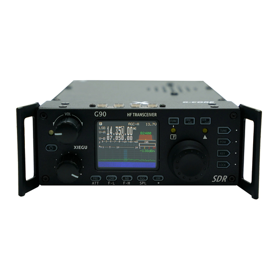
XIEGU G90 Operation Manual
Hf transceiver
Hide thumbs
Also See for G90:
- Operation manual (58 pages) ,
- Maintenance manual (48 pages) ,
- Operating instructions manual (38 pages)
Table of Contents
Advertisement
Advertisement
Table of Contents

Related Manuals for XIEGU G90


Summary of Contents for XIEGU G90
- Page 1 Version 4.3 – May 2023 (for G90 units with firmware v1.8).
- Page 2 Ultra-Miniature 24 Bit SDR...
-
Page 3: About Radioddity
Customer Support team, we strive to fulfill our promise to better meet your needs every day. In order to protect your rights please read the terms on XIEGU Warranty Card carefully and know the Warranty Policy. -
Page 4: Warnings
We would like to extend sincere gratitude to Radioddity's ham friends -- Bob Nagy (AB5N), Garry F. Decker (W9WHF) and Ed Durrant (DD5LP), for their instructive advice and useful suggestions in this G90 English manual. -
Page 5: Introduction
Please read this manual carefully for a better experience and a full understanding of the operation of the G90/S. ■ The G90S is the version sold in the People's Republic of China, the G90 is the version available in other countries. This operation manual is applicable to both models. -
Page 6: Table Of Contents
INDEX About Radioddity ....................3 Warnings ......................4 Copyright ......................4 Introduction ......................5 Specifications ....................8 Accessories and optional components ............10 Interface Definition ..................11 Machine Interface – Front panel ..............12 Machine Interface - Rear Panel ..............13 Machine Interface –... - Page 7 Automatic Gain Control (AGC) ..............28 PRE-AMP/ATT (combined control) ............29 Pulse Interface Suppressor – Noise Blanker .......... 29 Voice Compression CMP................30 CW (Morse Code) Communication ............30 CW Keyer settings ..................31 SSB Voice Communication ............... 32 Voice-controlled Transmit - VOX .............. 33 Setting Line level Input into ACC connector: ..........
-
Page 8: Specifications
Specifications General parameters Frequency range: RX: 0.5MHz-30MHz 1.8-2.0MHz 3.5-4.0MHz 5.330.5-5.405MHz 1 *3 7.0-7.3MHz 10.1-10.15MHz 14.0-14.35MHz 18.068-18.168MHz 21.0-21.450MHz 24.89-24.99MHz 28.0-29.7MHz Operating modes: USB/U-D/LSB/L-D/CW/CWR/AM/FM Minimum step: 10Hz Antenna impedance: 50Ω Working temperature: 0°C ~ +50°C Frequency stability: ±1.5ppm in the 10~60min after startup @25°C: 1ppm/hour Power supply voltage:... - Page 9 The two data modes U-D and L-D were added in FW v 1.79b02 ♦ The G90/S covers the range needed for the US 60m channels and the WRTC15 ITU band. It does not cover the bottom half of the UK 60m “bandlets”...
-
Page 10: Accessories And Optional Components
PAX-100: Radioddity HF 100W PEP amplifier. GNR 1: Xiegu Digital Audio Noise Filter Unit. NOTE: The G90/S is dealer modifiable for use on the US MARS required transmit frequency ranges. NOTE: Your antenna will have a great impact on the quality of your communications. -
Page 11: Interface Definition
Interface Definition Definition of microphone interface Wiring diagram of COMM plug Wiring diagram of earphone plug signal Left and right connections carry monaural audio Rear ACC socket Wiring of CW keys Common Common Note: ♦ If the connector of the CW key is a 6.5mm 2-wire plug, please change it to a 3-connector 3.5mm stereo plug according to the wiring method shown in the figure above. -
Page 12: Machine Interface - Front Panel
Machine Interface – Front panel Volume knob • Turn the knob to increase or decrease the volume. • A momentary press alternates between headphone/speaker output. Power supply /transceiver indicator light • Standby /receive state: yellow-green; • Red indicates the radio is transmitting. Power (on/off) switch •... -
Page 13: Machine Interface - Rear Panel
FUNC indicator This LED will light when the second function of a button is activated. 10 Δ F indicator This LED blinks when the CW signal is tuned in when in CW mode allowing the CW decoder to work. Main VFO/Mem tuning knob Change the current frequency by rotating this knob. -
Page 14: Machine Interface - Head Unit
Ground terminal Good grounding can improve the receiving and transmitting performance of the G90/S and reduce the possibility of RF ingress. Machine Interface – Head Unit MIC (microphone) interface (located on the right-hand side) Used to connect the included multi-function handheld microphone. - Page 15 Notes: 1. Insert the supplied 3.5mm to USB cable into this port for data transfer or CAT control mode communications. 2. Do not insert the cable into this port before you start the G90/S up.
-
Page 16: Hand Microphone Buttons
Hand Microphone Buttons 1. LOCK button Lock button 2. PTT button Press to transmit Frequency increase/ decrease button (user- 3. Up/down defined in the system menu) 4. Transmit/receive indicator light Transmission in progress indicator light 5. Main keypad area Main numeric keypad area 6. -
Page 17: Power Source Connection
8A. Use the provided cable to connect the G90/S to your DC supply. The G90/S transmitter is designed in such a way that dropping supply voltage from a weak battery has little effect on the transmitter output power until 10.5v is reached. -
Page 18: Functions Of The Buttons
Functions of the buttons Second function (FUNC+) First function Button (quick press so light Long press (momentary press, cycle) comes on) PRE - ATT - Normal. cycles through PRE/ATT these states. Digital filter F-L, low-pass cut-off Reset filter CMP/F-L Turn on voice compression frequency selection using the parameters main tuning knob... -
Page 19: Operation Of A Button's Second Function
Operation of a button’s second function: Press the [FUNC] button - the F indicator LED will illuminate, then press the required function’s button. Press the [FUNC] button again to exit the secondary function. At this time, the F indicator LED will go off. Pressing the [FUNC] button for 1-2 seconds will take you into the System Menu (see later in this manual for details of parameters that can be set). -
Page 20: Function And Definition Of Displayed Icons
Function and definition of displayed icons: : pre-amplifier is ON. The icon character A indicates that the attenuator is in- line. No character indicates Normal mode. : noise blanker is ON : automatic antenna tuner is in circuit. : voice compression CMP is active : squelch is ON : voice triggered TX control function is ON : AGC control is set to Slow (alternatively AGC-F, AGC-AUTO, AGC... -
Page 21: Operation
Operation In order to familiarize yourself with the functions and capabilities of the G90/S portable transceiver, please read the operation guide fully to understand the powerful functions of the G90/S. Transceiver start and shutdown 1. To start the transceiver: press the button for a short period of time. -
Page 22: Selection Of Working Frequency Range
Selection of Working Frequency Range The G90/S receives 0.5~30MHz but is set to only transmit on the amateur radio bands. The amateur bands are divided into 10 frequency blocks. Operation methods: Pressing the [<] or [>] BAND buttons will cycle through these bands. -
Page 23: Operating Mode Selection
Operating Mode Selection Press the [MODE] button to switch through all transmission modes: LSB – L-D – USB – U-D – CW – CWR – NFM – AM The two data modes LSB-Data (L-D) and USB-Data (U-D) were added in FW 1.79b02. Volume adjustment Speaker mode: Turn the volume knob to the left or right to adjust the... -
Page 24: Call Sign Editor
4. When the radio is re-started, your callsign will be displayed on the screen. Main knob Setting Operational Frequency. There are three methods to set the frequency of G90/S. You may use the large main knob, the multi-function knob or the keypad buttons on the hand microphone. -
Page 25: Adjustment Of Rf Gain And Muting Level
Press [F-INP ENT] button again to complete the action. 3. Quick adjustment of the frequency with the multi-function knob The Multi-function Adjustment Knob of the G90/S provides a method to quickly tune across the band. The function knob’s default function and increment is 100khz. -
Page 26: Squelch Operation (Prior To Firmware V 1.75)
Squelch Operation (prior to firmware v 1.75) 1. Apply a long press on the [Multi-function Adjustment Knob] to enter the user defined function menu. Rotate the main knob to select the SQL Level option. 2. Rotate the [Multi-function Adjustment Knob] to set the squelch muting level. At the same time, the muting level will show on the S meter. -
Page 27: Reception And Transmission Operations Using Spl And Vfoa/B
VFOA/B VFO operation Split Frequency Operation The G90/S transceiver has two built-in, independent, VFOs which can be set to different frequencies and different modes. Using the SPL (split) function, you can transmit and receive on different frequencies or even bands. -
Page 28: Automatic Gain Control (Agc)
VFO setting: 1. Momentarily press the [A/B / A>B] button to switch between VFO-A and VFO- 2. Set the required VFO frequency and mode when on one VFO (A or B). Split Operation (SPL); 1. Set the required receive frequency and mode on VFO-A first; 2. -
Page 29: Pre-Amp/Att (Combined Control)
changing in strength due to fading (QSB). You must manually control the RF gain level so that you do not have distortion from the incoming signal overloading the receiver. Set AGC to “off”, then go into the RF gain setting (Hold the AGC button in for 2 seconds) then adjust the main knob until the signal sounds clear. -
Page 30: Voice Compression Cmp
4. The radio will key into transmit when the Morse code key is pressed. Practice mode You can use the G90/S as a CW code trainer using the following method: ■ Disable the QSK function for the [KEY] function. Only the CW sidetone of the... -
Page 31: Cw Keyer Settings
When using automatic CW decoding, for best results, the bandwidth of the receiving filter should be set to 300Hz. Also, adjust the keyer speed on the G90/S to approximately the speed of the incoming CW for the best decoding results. The G90/S’s CW decoder is capable of excellent performance when adjusted correctly. -
Page 32: Ssb Voice Communication
To enter the second function of the [KEY] button press [FUNC] button and then [KEY] to select and set the following options. Once adjusted using the main tuning knob, press the KEY button again to exits the settings process. Options: CW Volume: sidetone volume setting T800Hz: sidetone tone frequency setting B500: CW receiving bandwidth setting (the default value is 500Hz) –... -
Page 33: Voice-Controlled Transmit - Vox
Voice-controlled Transmit - VOX The voice-controlled transmission (VOX) feature can automatically judge whether there is a hand microphone connected or if audio is coming from the line input signal (on the ACC socket). It will automatically control the radio switching between the receive and transmit when audio is detected. When the VOX function is activated, it is unnecessary to press the hand microphone PTT key to start the transmission. -
Page 34: Automatic Antenna Tuner
Automatic Antenna Tuner The G90/S has an efficient ATU to help you quickly match many kinds of antennas effectively. 1. Press the [TUNE] button in momentarily to bring the built-in antenna tuner into circuit. An antenna icon will appear at the top of screen. -
Page 35: Corresponding Location Of Keys Vs. Screen Labels
4. Press the button below the FAST/ SLOW label on the screen momentarily to select the scanning speed. 5. Press the button below the QUIT label on the screen to exit the standing- wave scanner. Corresponding location of keys VS. screen labels: (They are not perfectly aligned vertically) ♦... -
Page 36: Line Input And Output
Line Input and Output The G90/S has an external line input interface. When the G90/S is used for data communication in conjunction with a computer or an external modem, the correct signal input options need to be selected. 1. Feed the external audio signal into the corresponding pin of the ACC port (see the interface description on page 10). -
Page 37: Channel Memory Write (Mw) And Clear (Mc)
Channel Memory Write (MW) and Clear (MC) Basic operations: 1. While in VFO mode, set the required frequency, mode, and any other parameters you desire. 2. Press the [MW/MC] button momentarily and the CH 00 (channel number) character will appear on the screen flashing. Rotate the main tuning knob to select an empty channel. -
Page 38: Digital (Dsp) Filters
With FW v 1.79b02 the G90 changed to an updated 2 BPF mode –The band- pass filter is changed to allow 2 BPF defaults that can be switched between. -
Page 39: Receive Filter Operation Prior To Firmware V 1.79B02
Receive filter operation prior to firmware v 1.79b02: The G90/S has two filter adjustment modes: center frequency point mode and bandwidth mode. 1. Press the [Multi-function] knob momentarily to switch between the two filter modes. 2. When the center frequency point mode is selected: The prompt text "Cxxx"... -
Page 40: Spectrum/ Waterfall Display
300-500 Hz is normally ideal. Spectrum/ Waterfall Display The G90/S radio can display the radio spectrum and waterfall diagrams of received signals and you can quickly observe whether there is a signal on the desired frequency of operation. You can also easily identify a clear frequency to QSY (move freq.) to in case there is QRM (interference) occurring on the... -
Page 41: Data Communication
This setting is a matter of personal taste. It can improve usability of the spectrum display. Data Communication The G90/S supports all PC-generated amateur data communication modes and remote control via computer software when a PC is linked to the radio. Only simple wiring is needed to enable amateur data communications. The optional... -
Page 42: Cable Connection Steps
4. Either select a data mode e.g. U-D (only after FW 1.79b02 or later has been installed). If using an older firmware level, you will have to set the G90/S to "Line input" mode (i.e. take the audio from the ACC socket rather than from the hand microphone.) and set the G90/S to the appropriate TX mode for the particular... -
Page 43: Digital Mode Connections
the power set as the radio’s power output setting. This is so the signal is perfectly clean for digital operation and to avoid the radio overheating. This is normal procedure for digital modes. ■ You can add clamp-on ferrite RF chokes to the USB data cable and the ACC cable if you experience any stray RF getting from the radio into the PC. - Page 44 The wiring of the 3.5mm sockets are shown on the CE-19 board. The port labelled X5105 is also for the G90/S and accepts the 8-core cable from the ACC port of the radio. 8-core ACC connecting The audio cable is connected as follows: line AF_OUT: to PC Audio input.
-
Page 45: Factory Reset
XPA125B, the ALC control automatically decreases the G90/S’s output power to avoid over-driving the amplifier. The output power of the G90/S should be set to be ≤2.5W to protect the amplifier. The amplifier can give full output power with very little drive on the input socket. -
Page 46: System Menu
System Menu The system menu enables a good amount of customization. Many of these are a matter of personal preference. Operation method: Hold the [FUNC] button 1-2 sec. to enter the system menu. The definitions of menu functions are as follows: Menu item Function description Hand... - Page 47 Function: Customize the function of [F1] button on the hand microphone. Possible PRE/ATT options: SPLT COMP Default: PRE/ATT Menu item 3: Handle F2 Function: Customize the function of [F2] button on the hand microphone. Possible PRE/ATT options: SPLT COMP Default: SPLT Menu item 4: LCD BL Function: Set the brightness of the backlit display Adjustable range: 10%~100%...
- Page 48 i.e.: If you are showing a consistent offset of 20Hz when you are talking to stations, you can adjust the reference frequency by 20Hz to re-calibrate. If you are 20Hz low on your frequency display, set the adjustment to be + 20Hz. Menu item 8: Band Stacking Mode Function: Set band stacking mode.
-
Page 49: Civ Control Instructions
CiV Control Instructions Computer Control Instructions The G90/S uses a subset of the standard CiV CAT instruction set. You can remotely control the transceiver based on standard instructions or configure control instructions for other software. Here are the tables of commands that currently work. With later firmware... - Page 50 Note as at 14-05-2023, function 0x26/0x01 is not working correctly USB-D is reported as USB and LSB-D as LSB from the non-selected VFO.
-
Page 51: Band Voltage Data
– the ICOM ® connector is a 3.5mm mono connector and uses one wire for both Tx and Rx data. The XIEGU connector is a stereo plug with Rx and Tx data on separate rings of the plug. Band Voltage Data The ACC socket contains a “BAND”... -
Page 52: Firmware Upgrades
G90/S will be there. The USB cable for performing updates is included with the G90/S or you can perform the upgrade via the (optional) DE-19 unit. Be sure to install the appropriate driver from the Radioddity website on your PC before inserting the USB cable into your PC. - Page 53 Mode BPF1 BPF2 Bandwidth (kHz) 300 ~ 3000 300 ~ 3000 2700 SSB DIG 100 ~ 3100 100 ~ 3100 3000 -250 ~ 250 -250 ~ 250 -3000 ~ 3000 -3000 ~ 3000 6000 -4500 ~ 4500 -4500 ~ 4500 9000 Note: Negative numbers for frequency indicate that the frequency being used is to the left of the center of the spectrum (i.e.
- Page 54 GSOC. Compatibility with GD MCU and ST MCU Note: G90 after the product serial number X04G211600001 must use the firmware version after V1.77 (including 1.77V), if it is updated to the firmware version before 1.77V, it may not work normally What’s new in v1.7.5...
- Page 55 5. Add RF GAIN to Multi-Function Knob function list 6. Lower CW Tone volume (-15dB lower than the original level) 7. Set Narrow FM modulation frequency deviation to about +/-3.5kHz 8. Added Narrow FM SQL What’s new in v1.7.4 1. Fixed the problem that MIC Gain is relatively high 2.
- Page 56 Adjust it to your personal preference. Copyright Statement All Rights Reserved, 2022 Chongqing Xiegu Technology Co., Ltd. reserves all rights of the manual. All parts of the manual shall not be copied without permission. 1010160204-C...
Need help?
Do you have a question about the G90 and is the answer not in the manual?
Questions and answers