XIEGU G90 Operating Instructions Manual
Portable sdr hf transceiver with built-in auto antenna tuner
Hide thumbs
Also See for G90:
- Operation manual (58 pages) ,
- Maintenance manual (48 pages) ,
- Cheat sheet (13 pages)

Related Manuals for XIEGU G90


Summary of Contents for XIEGU G90
- Page 1 Portable SDR HF Transceiver with inbuilt ATU Operating instructions SINOTEL UK LIMITED 2019 V1.00.04...
-
Page 2: Table Of Contents
Power On/Off Computer Control Instruction Set Band Selection Band Voltage Data Operating Mode Selection Specifications Volume/VOX Setting Contents of Carton Multi-function Knob (MFK) G90 and XPA125B Connection Transmit Power Adjustment CE-19 Expansion Adapter Diagram Frequency Selection Copyright Statement Antenna Tuning (ATU) -
Page 3: Panel Buttons
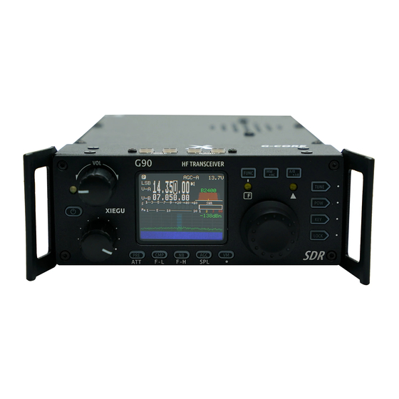
The Xiegu G90 is a portable 20W HF amateur radio transceiver with 24-bit 48 kHz SDR architecture and a built-in automatic antenna tuner. The display panel and the main unit can be separated to enable remote mounting of the display panel. It delivers excellent performance on both transmit and receive and is highly configurable. Standout features include the following: ... -
Page 5: Front Panel Controls
1. Volume knob 5-6. Mode switching Turn to adjust the AF volume. Short press to switch to headphone mode. Mode switching. 2. Power/Receive/Transmit LED 7-8. Band Switching Standby/receive status - yellow-green; Band switching. Transmitting status - red; ... -
Page 6: 12. Function Buttons
12. Function buttons Button definitions and functions are detailed in the operation section starting on page 21. -
Page 7: Rear Panel Layout & Controls
13. Antenna interface 16. I/Q Signal low level baseband output socket SO-239 type,impedance 50 Ω. 3.5mm stereo jack socket to output the spectrum/waterfall display on a PC via a soundcard with a stereo input. 14. CW KEY socket 17. Accessory socket 3.5mm stereo jack socket for connection of 8-pin mini DIN socket for digital modes &... -
Page 8: Side Panel Sockets
MIC Connector (Right side of the display unit) Plug the multi-function microphone into this connector. 21. Headphone socket (Left side of the display unit) 3.5mm stereo jack socket for connecting headphones (stereo only). 22. Communication interface (Left side of the display unit) For firmware updates to the display unit. -
Page 9: Connector Pinouts
4. ACC Socket 1. MIC interface MICE G N D D A TA MSVSW A F_O U T + 8V A F_I N A LC MDATA B A N D 5. Iambic CW key wiring diagram 2. COMM plug R X D G N D Ground TX D... -
Page 10: Microphone Controls
Lock button LOCK Transmit control button Frequency up/down buttons UP/DOWN RX/TX operation indicator Receive/transmit LED Numeric keypad area Numeric keypad Filter selection Operating mode selection MODE Not used Function indicator F1/F2 self-defined setting button Function button Memory storage operation 10. MW Frequency/channel switching 11. -
Page 11: Power Connection
The G90 will operate best with a 13.8V external DC power supply with a continuous current load capacity of at least 10A. The supplied power cable must be used to connect the radio to the DC power source. Please note the polarity of the wiring before connecting your radio to a power source. Reversing the polarity can cause damage to the transceiver that will not be covered under warranty. - Page 12 Wrap power cable twice around the ferrite ring, as close as possible to the radio power socket.
-
Page 13: Lcd Display
The G90 uses a multifunction menu system to access various functions. The LCD display shows functions and operating parameters as follows: Input voltage Main frequency display Status Display Mode AF Volume VFO status Function display area SWR meter S-meter and power meter... -
Page 14: Power On/Off
Powering the transceiver on and off To turn on, press and hold button. To turn off, press and hold button for one second or more. Power button To turn off the display, press the button briefly. To reactivate the display, press again, or press any other button or rotate any control knob. -
Page 15: Band Selection
3.5MHz 1.8MHz 5.2MHz 14MHz 7.0MHz 10MHz 28MHz 21MHz 24MHz 18MHz Available frequencies may differ depending on the regulations applicable to the specific country or region in which the G90 is sold. -
Page 16: Operating Mode Selection
Operating mode selection MODE] Press either [ button to cycle through the operating modes as follows: : Mode down Mode up Different operating modes can be set for VFO-A and VFO-B. NOTE: The FM mode can only be activated when the GSOC controller/panadapter is connected. -
Page 17: Volume/Vox Setting
Volume Control Rotate the volume knob left or right to adjust the AF output volume. Briefly press the volume knob inwards to select headphone mode. VOX mode Press the [FUNC] button, then briefly press the volume knob inwards to access the VOX menu settings as follows: VOX OFF/ON: To activate/deactivate the Vox function. -
Page 18: Multifunction Knob (Mfk)
Multifunction knob (MFK) The operation of the multifunction knob can be customized according to your own preference. Use of the MFK: By default, turning the MFK will change the Multi-function adjustment knob selected frequency in 100 kHz steps. To allocate a different function, press and hold the MFK for two seconds, then rotate the main tuning knob to select one of the options that appear on the display screen: 1) Change frequency in 100 kHz steps;... -
Page 19: Transmit Power Adjustment
When using the G90 transceiver for the first time with a new antenna, we recommend setting the RF transmit power to the lowest possible level to avoid damaging the transceiver due to an antenna mismatch. -
Page 20: Frequency Selection
Inputting a frequency directly using the microphone keypad: Press the [F-INP ENT] button on the microphone. On the G90 display, the cursor will flash awaiting input; Enter the frequency value you want to select, including point separator, and press the [F-INP ENT] button again to confirm. -
Page 21: Antenna Tuning (Atu)
Automatic Antenna Tuner (ATU) The G90 is equipped with an efficient integrated automatic antenna tuner (ATU) that can help you quickly match your antenna to the desired frequency. Tune Briefly press the [TUNE] button to activate the ATU. "TUNE" will be displayed at the top of the screen;... -
Page 22: Function Buttons
Function buttons The buttons below the display each have two functions. The second function is accessed by first pressing the button (the LED below it will light up yellow), and then pressing [FUNC] the appropriate button. To return to the first function, press the button again. -
Page 23: Function Button Table
Function button table Button Function 1 Function 2 Press & hold PRE/ATT Preamp/attenuator switching in/out CMP/F-L Transmit voice compression on/off (SSB/AM only) Digital filter F-L lower frequency selection NB/F-H Noise blanker on/level/width (set level/width with main control knob) Digital filter F-H upper frequency selection AGC/SPL Automatic Gain Control Off/Slow/Fast/Auto Select Turn on split frequency transceiver operation mode... -
Page 24: Split Frequency Operation (Spl) And Vfo A/B Settings
Split frequency operation (SPL) and VFO A/B settings The G90 has two independent VFOs. Different VFO A/B selection frequencies and modes can be set for VFO A and B. This is useful for split frequency operation. VFO Selection: Press the [A/B/A>B] button to switch between VFO-A and VFO-B. -
Page 25: Cw Operation
To do so, switch the QSK function off using the [KEY] button function. When the QSK Time CW key is operated, the G90 will emit CW tones, but no RF signal will be emitted, Ratio:auto key "." "-" interval... -
Page 26: Standing Wave Ratio (Swr) Scanning
Standing wave ratio (SWR) scanning The G90 has an SWR scanning function which can give an indication of the SWR of the antenna connected to the transceiver. You can also set the threshold of the high SWR warning provided on the display to any level between 1.8 and 3.6. -
Page 27: Digital Filter
Digital filter The G90 has a built-in digital filter. The bandwidth of the filter can be adjusted to suit band conditions and your own listening preference. Operation: Press the [FUNC] button; Bandwidth value Press the [CMP/F-L] button followed by the [NB/F-H] button;... -
Page 28: Line Input/Output Selection And Adjustment
Line input/output selection and adjustment The G90 has an external communication (ACC) socket. When connecting to a computer or an external interface for data communication, the appropriate settings should be selected as follows: Line input selection and level adjustment: ... -
Page 29: Storing And Deleting Memory Channels
Storing and deleting memory channels 64 Memory channels are provided. Storing a channel in the memory: In the VFO mode, set the desired frequency, operating mode and any other required parameters; Press the [MW/MC] button. CH 00 (the channel number) will appear on the display and flash. Rotate the main control knob to select the required channel. -
Page 30: Power-On Display Call Sign Setting
Power-on display call sign setting The G90 can be set to show your call sign or other text on the display when powering up. Setting: Press and hold the [VM] button to enter the text editor; At the bottom of the display is the character selection area. Rotate the main control knob to select the desired character. Press the main control knob to select the character;... -
Page 31: System Menu Description
System menu description Press and hold the [FUNC] button to enter the system menu; Press the [VM] and [PRE] buttons to move through the menu items; Rotate the main control knob to select the required function parameter; Press the [CMP] button to save and exit, or the [AGC] button to exit without saving The various menu functions are defined as follows: Menu item number Menu name... -
Page 32: Computer Connection For Data Modes
Connect the G90's audio output (AF_OUT pin of the ACC port) to the computer's audio input port. Set the output signal level (see page 27); Connect the audio output of the computer to the audio input port of the G90 (AF_IN pin of the ACC port). Set the input signal level (see page 27);... -
Page 33: Computer Control Instruction Set
Computer control instruction set The G90 uses the standard CIV instruction set. You can use the standard instructions of this instruction set to remotely control the transceiver. It can also be used to configure the control instructions of other software to control the G90. -
Page 34: Specifications
Specifications Receiver Adjacent channel suppression: ≥60 dB General Sideband suppression: ≥60 dB Frequency Range: Sensitivity: Receive: 0.5 - 30 MHz Transmit: 0.5 - 30 MHz (amateur bands SSB/CW/FM only) Transmission modes: A1A(CW)/A3E(AM)/J3E(SSB) 0.5 - 1.79999MHz 10uV Minimum frequency step: 10 Hz 1.8 - 1.9999MHz 0.35uV 10uV... -
Page 35: Contents Of Carton
Packing List Item Quantity G90 transceiver Multi-function Microphone USB Data cable Power cable Operation Manual Warranty Card Fixed stud for remote head use Allen key Certificate * Optional accessories Item Description CE-19 ACC expansion adapter XPA125B 100W power amplifier with built-in ATU... -
Page 36: G90 And Xpa125B Connection
Connection diagram between G90 and XPA125B using the optional CE-19 interface TO XPA125 ACC口 CE-19 XPA125B 6芯线 8芯线 8 Pin 6 Pin *Note:The 8-core ACC control cable is included in the CE-19 kit. -
Page 37: Expansion Adapter Diagram
CE-19 expansion adapter interface diagram PTT CON PTT signal/BAND signal output port. The PTT signal at this port is completely isolated from the transceiver and provides a low level trigger output. TO XPA125B XPA12B dedicated interface. AF CON Audio input/output port. The audio output from this port is directly output after demodulation, unfiltered. DATA CON Data output port in NFM mode. -
Page 38: Copyright Statement
All rights reserved 2019 by Chongqing Xiegu Technology Co., Ltd. Reproduction of any part of this manual is prohibited without permission. This edition revised & amended October 2019 by Alan Clunnie (M0RYZ) of Sinotel UK Limited. V1.0.04 1010160204-C...
Need help?
Do you have a question about the G90 and is the answer not in the manual?
Questions and answers