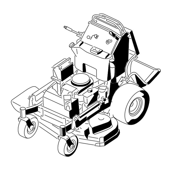
Toro GrandStand 79534 Operator's Manual
Mower with 36in or 40in turbo force cutting unit
Hide thumbs
Also See for GrandStand 79534:
- Operator's manual (64 pages) ,
- Operator's manual (64 pages) ,
- Operator's manual (64 pages)
Table of Contents
Advertisement
Quick Links
Advertisement
Table of Contents

Related Manuals for Toro GrandStand 79534


Summary of Contents for Toro GrandStand 79534
- Page 1 Mower With 36in or 40in TURBO FORCE ® Cutting Unit Model No. 74534—Serial No. 316000001 and Up Model No. 74536—Serial No. 316000001 and Up Model No. 79534—Serial No. 316000001 and Up g020526 *3400-621* A Register at www.Toro.com. Original Instructions (EN)
- Page 2 You may contact Toro directly at www.Toro.com for product WARNING safety and operation training materials, accessory information, help finding a dealer, or to register your product. CALIFORNIA Proposition 65 Warning Whenever you need service, genuine Toro parts, or additional This product contains a chemical or chemicals...
-
Page 3: Table Of Contents
Cooling System Maintenance ........42 Safety ................4 Cleaning the Air-Intake Screen .........42 Safe Operating Practices........... 4 Cleaning the Cooling System........42 Toro Mower Safety ..........6 Brake Maintenance ............43 Slope Indicator ............7 Servicing the Brake ..........43 Safety and Instructional Decals ......... 8 Belt Maintenance ............44... -
Page 4: Safety
Use extra care when handling fuels. They are flammable only be made by either the manufacturer or an Authorized and vapors are explosive. Toro Dealer. – Use only an approved container. This product is capable of amputating hands and feet. Follow –... - Page 5 Hauling • Stop on level ground, disengage drives, engage the parking brake, shut off the engine before leaving the • Use care when loading or unloading the machine into a operator's position for any reason, including emptying the trailer or a truck. catchers or unclogging the chute.
-
Page 6: Toro Mower Safety
Toro Mower Safety Slope Operation All slopes and ramps require extra caution. If you feel uneasy The following list contains safety information specific to Toro on a slope, do not mow it. products and other safety information that you must know. -
Page 7: Slope Indicator
Slope Indicator G011841 Figure 3 This page may be copied for personal use. 1. The maximum slope you can safely operate the machine on is 20 degrees. Use the slope chart to determine the degree of slope of hills before operating. Do not operate this machine on a slope greater than 20 degrees. Fold along the appropriate line to match the recommended slope. -
Page 8: Safety And Instructional Decals
Safety and Instructional Decals Safety decals and instructions are easily visible to the operator and are located near any area of potential danger. Replace any decal that is damaged or lost. Manufacturer's Mark 1. Indicates the blade is identified as a part from the original 93-7818 machine manufacturer. - Page 9 116-8775 115-4186 1. Read the Operator’s 2. Fill to bottom of filler neck; Manual. warning—do not overfill 1. Interval the tank. 2. Power takeoff (PTO) 3. Parking brake 4. Neutral 5. Operator-presence switch 6. Battery 115-4212 1. Hydraulic oil level 3.
- Page 10 119-0217 1. Warning—stop the engine; stay away from moving parts; keep all guards and shields in place. 119-1854 1. Adjustment knob for traction drive speed 119-0186 36-inch Mower Deck 1. Belt routing 119-2317 1. Height-of-cut (inches) 121-6049 119-0187 1. Thrown object 3.
- Page 11 117-0454 1. Traction control 5. Reverse 3. Slow 7. Operator-presence switch 2. Fast 4. Neutral 6. Power takeoff (PTO)—disengage 117-3626 1. Warning—read the Operator's Manual. 5. Thrown object hazard—keep bystanders a safe distance from the machine. 2. Warning—do not operate this machine unless you are trained. 6. Warning—engage the parking brake, stop the engine and remove the spark plug wire before performing any maintenance on the machine.
-
Page 12: Product Overview
Controls Product Overview Become familiar with all the controls (Figure 5) before you start the engine and operate the machine. G020528 Figure 4 1. Side-discharge chute 7. Operator cushion G020529 2. Battery 8. Platform (down position) 3. Engine 9. Hydraulic tank Figure 5 4. -
Page 13: Specifications
(Figure available for use with the machine to enhance and expand its capabilities. Contact your Authorized Service Dealer or Distributor or go to www.Toro.com for a list of all approved Safety-interlock Indicators attachments and accessories. There are symbols on the hour meter that indicate with a... -
Page 14: Operation
Operation DANGER In certain conditions, gasoline is extremely Think Safety First flammable and highly explosive. A fire or explosion from gasoline can burn you and others and can Carefully read all the safety instructions and decals in the damage property. safety section. -
Page 15: Checking The Engine-Oil Level
additional load on the engine. Allow 40 to 50 hours of WARNING break-in time for new machines to develop full power and Gasoline is harmful or fatal if swallowed. Long-term best performance. exposure to vapors can cause serious injury and illness. -
Page 16: Operating The Mower-Blade-Control Switch (Pto)
Operating the Mower-Blade-Control Switch (PTO) The blade-control switch (PTO) is used in conjunction with the right motion-control lever to engage and disengage the mower blades. g012895 Engaging the Mower Blades (PTO) Figure 11 1. To engage the mower blades, move the right motion-control lever to the center, unlocked position. -
Page 17: Operating The Ignition Switch
Using the Fuel-Shutoff Valve The fuel-shutoff valve is located behind the right side of the operator cushion. Close the fuel-shutoff valve for transport, maintenance, and storage (Figure 16). Ensure that the fuel-shutoff valve is open when starting the engine. g020864 G008959 Figure 13 1. -
Page 18: Starting And Stopping The Engine
Starting and Stopping the Stopping the Engine Engine CAUTION Children or bystanders may be injured if they Starting the Engine move or attempt to operate the tractor while it is unattended. Important: Do not engage the starter for more than 5 seconds at a time. -
Page 19: Using The Safety-Interlock System
Using the Safety-Interlock 3. Move the right motion-control lever to the center, unlocked position. System Note: The blades should not rotate. CAUTION 4. Move the motion-control levers forward. If the safety-interlock switches are disconnected or Note: The engine should stop running. damaged, the machine could operate unexpectedly, 5. -
Page 20: Operating The Platform
Operating the Platform You can use the machine with the platform in the up or down position. It is your preference on which position to use. Operating the Machine with the Platform Up Operate the machine with the platform up for the following conditions: •... - Page 21 Figure 22 Driving Backward G020531 1. Move the right motion-control lever to the center, Figure 21 unlocked position. 1. Front reference bar 4. Right control lever 2. Slowly pull the motion-control levers rearward (Figure 2. Left control lever 5. Right control lever in the 23).
-
Page 22: Stopping The Machine
Stopping the Machine To stop the machine, move the motion-control levers to , move the right motion-control lever into the EUTRAL position, disengage the power takeoff EUTRAL LOCK (PTO), and turn the ignition key to the O position. Set the parking brake when you leave the machine; refer to Setting the Parking Brake (page 15). -
Page 23: Loading The Machine
WARNING Loading a machine onto a trailer or truck increases the possibility of tip-over and could cause serious injury or death. • Use extreme caution when operating a machine on a ramp. • Use only a full-width ramp; do not use individual ramps for each side of the machine. -
Page 24: Side Discharging Or Mulching The Grass
Side Discharging or Mulching the Grass This mower has a hinged grass deflector that disperses clippings to the side and down toward the turf. DANGER Without the grass deflector, discharge cover, or complete grass catcher assembly mounted in place, you and others are exposed to blade contact and thrown debris. -
Page 25: Adjusting The Flow Baffle
Positioning the Flow Baffle The following figures are only for recommended use. Adjustments vary by grass type, moisture content, and the height of the grass. Note: If the engine power draws down, and the mower ground speed is the same, open up the baffle. Position A This is the full, rear position (see Figure... -
Page 26: Using Counterweights
Position B • You can add or remove weights to create optimized performance under different mowing conditions and for Use this position when bagging (Figure 31). your preference. • Add or remove 1 at a time until you achieve the desired handing and balance. -
Page 27: Maintenance
• Check and adjust the valve clearance. See an Authorized Service Dealer. Every 300 hours • Adjust the caster-pivot bearing. • Change the hydraulic fluid when using Toro® HYPR-OIL™ 500 hydraulic fluid. Every 500 hours • Change the hydraulic filter. -
Page 28: Premaintenance Procedures
Premaintenance Procedures Raising the Mower for Access You can raise the front of the mower and support it on its back for access under the machine for maintenance. 1. Raise the platform; refer to Operating the Platform (page 20). 2. Remove the battery; refer to Removing the Battery (page 37). -
Page 29: Releasing The Cushion For Rear Access
Releasing the Cushion for Rear Access You can release the cushion for rear access to the machine for maintenance or adjustment. 1. Lower the platform. 2. Remove the hairpin cotters on each side of the cushion. 3. Slide the large washers with plastic bushings to the inside. -
Page 30: Lubrication
Lubrication Grease with No. 2 lithium or molybdenum grease. Lubricating the Machine Service Interval: Every 50 hours—Grease the mower-deck idler arms (more often in dirty or dusty conditions). Every 50 hours—Grease the lift linkage (more often in dirty or dusty conditions). 1. -
Page 31: Lubricating The Caster-Wheel Hubs
Lubricating the Caster-Wheel 13. Torque the nut to 8 to 9 N∙m (71 to 80 in-lb), loosen it, then torque it to 2 to 3 N∙m (20 to 25 in-lb). Hubs Note: Make sure that the axle does not extend beyond Service Interval: Yearly either nut. -
Page 32: Engine Maintenance
Engine Maintenance Cleaning the Foam Air-Cleaner Element Service Interval: Every 25 hours Servicing the Air Cleaner 1. Wash the foam element in liquid soap and warm water. When the element is clean, rinse it thoroughly. Service Interval: Every 300 hours 2. -
Page 33: Servicing The Engine Oil
Servicing the Engine Oil 2. Shut off the engine, remove the key, and wait for all moving parts to stop before leaving the operating Service Interval: Before each use or daily—Check the position (Figure 43). engine-oil level. After the first 8 hours—Change the engine oil. Every 100 hours—Change the engine oil (more often in dirty or dusty conditions). - Page 34 Changing the Engine Oil Note: Dispose of the used oil at a recycling center. 1. Park the machine so that the drain side is slightly lower than the opposite side to assure the oil drains completely. 2. Disengage the PTO, move the motion-control levers to the N position and set the parking brake.
-
Page 35: Servicing The Spark Plug
Removing the Spark Plug 1. Disengage the PTO, move the motion-control levers to the N position, and set the parking brake. EUTRAL LOCK 2. Shut off the engine, remove the key, and wait for all moving parts to stop before leaving the operating position. -
Page 36: Checking The Spark Arrester
Installing the Spark Plug Fuel System Maintenance Draining the Fuel Tank Note: The only recommended way to drain fuel from the tank is to use a syphon pump. A syphon pump can be purchased at a hardware store. DANGER 16 ft-lb 22 N-m In certain conditions, gasoline is extremely flammable and highly explosive. -
Page 37: Servicing The Fuel Filter
Servicing the Fuel Filter Electrical System Maintenance Replacing the Fuel Filter Service Interval: Yearly Servicing the Battery Never install a dirty filter if it is removed from the fuel line. Service Interval: Every 100 hours Note: Wipe up any spilled fuel. Always keep the battery clean and fully charged. - Page 38 WARNING Incorrect battery cable routing could damage the machine and cables causing sparks. Sparks can cause the battery gasses to explode, resulting in personal injury. • Always disconnect the negative (black) battery cable before disconnecting the positive (red) cable. • Always connect the positive (red) battery cable before reconnecting the negative (black) cable.
-
Page 39: Servicing The Fuses
Drive System 6. Install the battery onto the machine and connect the battery cables; refer to Installing the Battery (page 38). Maintenance Note: Do not run the machine with the battery disconnected; electrical damage may occur. Adjusting the Tracking Note: Determine the left and right sides of the machine from the normal operating position. - Page 40 6. Test the safety-interlock system before operation. 2 3 4 g017848 Figure 56 1. Left cable adjustment 3. Right cable adjustment 2. Cable lock 7. Check for proper tracking. Note: If the machine does not start after adjusting the tracking, make sure that the proximity switch target aligns with the bolt attached to the motion-control lever;...
-
Page 41: Checking The Tire Pressure
Checking the Tire Pressure Adjusting the Caster-Pivot Bearing Service Interval: Every 50 hours/Monthly (whichever comes first) Service Interval: Every 500 hours/Yearly (whichever comes Maintain the air pressure in the rear tires at 83 to 97 kPa (12 first) to 14 psi). 1. -
Page 42: Adjusting The Electric Clutch
Adjusting the Electric Clutch Cooling System Maintenance Service Interval: Every 100 hours—Check the electric clutch. The clutch is adjustable to ensure proper engagement and Cleaning the Air-Intake Screen proper braking. 1. Insert a 0.4 to 0.5 mm (0.01 to 0.02 inch) feeler gauge Service Interval: Before each use or daily through an inspection slot in the side of the assembly. -
Page 43: Brake Maintenance
Brake Maintenance Servicing the Brake Before each use, check the brakes on both a level surface and slope. Always set the parking brake when you stop the machine or leave it unattended. If the parking brake does not hold securely, adjust it. Checking the Parking Brake Service Interval: Before each use or daily Important: Ensure that the mower is on a level surface... -
Page 44: Belt Maintenance
Adjusting the Brakes Belt Maintenance If the gap between the brake bar and tire is not correct, adjust the brake. Checking the Belts 1. Park the machine on a level surface and disengage the Service Interval: Every 100 hours—Check the pump-drive PTO, and set the parking brake. -
Page 45: Replacing The Mower-Deck Belts
Figure 64 1. Belt 3. Spring Figure 65 2. Spring-loaded idler pulley 1. Belt 3. Spring-loaded idler pulley 2. Spring Replacing the Mower-Deck Belts Replacing the Left Mower-Deck Belt 1. Disengage the PTO and set the parking brake. For Models with a 40-Inch Deck 2. -
Page 46: Replacing The Pump-Drive Belt
Figure 66 1. Belt 3. Spring 2. Spring-loaded idler pulley Replacing the Pump-Drive Belt Service Interval: Every 100 hours—Check the pump-drive belt. 1. Disengage the PTO and set the parking brake. 2. Shut off the engine, remove the key, and wait for all moving parts to stop before leaving the operating position. -
Page 47: Controls System Maintenance
Controls System Maintenance Adjusting the Motion-Control Handle Positions Adjusting the Right Motion-Control Lever If the motion-control levers do not align horizontally, adjust the right motion-control lever. Note: Adjust the horizontal alignment before the front to back alignment. 1. Disengage the PTO, move the right motion-control lever to the N position, and set the parking EUTRAL... - Page 48 G012706 Figure 70 1. Left motion-control lever 3. Neutral-locked position 2. Right motion-control lever 4. Align the control levers front to back Figure 71 2. Ensure that the right motion-control lever moves easily 1. Left cable adjustment 3. Right cable adjustment into the N position.
-
Page 49: Hydraulic System Maintenance
72). Servicing the Hydraulic 9. Install the cap on the filler neck. System WARNING ® ™ Hydraulic Fluid Type: Toro HYPR-OIL 500 hydraulic Hydraulic fluid escaping under pressure can ® fluid or Mobil 1 15W-50 synthetic motor oil. penetrate skin and cause injury. - Page 50 Replacing the Hydraulic Filter Service Interval: After the first 8 hours Every 500 hours/Yearly (whichever comes first) WARNING Hot hydraulic fluid can cause severe burns. Allow the hydraulic fluid to cool before performing any maintenance to the hydraulic system. 1. Disengage the PTO and set the parking brake. Figure 73 2.
- Page 51 Checking the Hydraulic Hoses Service Interval: Every 100 hours Check the hydraulic hoses for leaks, loose fittings, kinks, loose mounting supports, wear, general weathering, and chemical deterioration. Make any necessary repairs before operating. Note: Keep areas around the hydraulic system clean from grass and debris buildup.
-
Page 52: Mower Deck Maintenance
Mower Deck Checking for Bent Blades 1. Disengage the PTO, move the motion-control levers to Maintenance the N position, and set the parking brake. EUTRAL LOCK 2. Shut off the engine, remove the key, and wait for all Servicing the Cutting Blades moving parts to stop before leaving the operating position. - Page 53 To ensure optimum performance and continued safety conformance of the machine, use blade is balanced. genuine Toro replacement blades. Replacement blades made by other manufacturers may result in nonconformance with safety standards. 1. Hold the blade end using a rag or a thickly padded glove.
-
Page 54: Leveling The Mower Deck
Leveling the Mower Deck Preparing the Machine 1. Position the machine on a flat surface. 2. Disengage the PTO, move the motion-control levers to the N position, and set the parking brake. EUTRAL LOCK 3. Shut off the engine, remove the key, and wait for all moving parts to stop before leaving the operating position. - Page 55 Adjusting the Right Side Front-to-Rear Mower Deck Pitch 1. Position the right blade front-to-rear (Figure 84). 2. Measure the right blade at the C location, from a level surface to the cutting edge of the blade tip, and record this measurement (Figure 84).
- Page 56 Matching the Rear of the Mower Deck Leveling the Front of the Mower Deck 1. Position the left and right blades front-to-rear. 1. Position the left and right blades front-to-rear. 2. Measure the left blade at the B location, from a level 2.
- Page 57 Matching the Height of Cut Adjusting the Compression Spring 1. Lower the mower to the 76 mm (3 inches) height-of-cut Note: Adjusting the compression spring alters how much position. the deck floats and how much effort it takes to lift the deck when using the height-of-cut handle.
-
Page 58: Replacing The Grass Deflector
Replacing the Grass Deflector Cleaning WARNING Cleaning under the Mower An uncovered discharge opening could allow the machine to throw objects in the operator's or Service Interval: Before each use or daily bystander's direction and result in serious injury. Remove the grass buildup under the mower daily. Also, contact with the blade could occur. -
Page 59: Storage
Storage Cleaning and Storage 1. Disengage the power takeoff (PTO), set the parking brake, turn the ignition key to off, and remove the key. 2. Remove grass clippings, dirt, and grime from the external parts of the entire machine, especially the engine. -
Page 60: Troubleshooting
Troubleshooting Problem Possible Cause Corrective Action The engine does not start, starts hard, or 1. The fuel tank is empty or the shutoff 1. Fill the fuel tank with gasoline and fails to keep running. valve is closed. open the valve 2. - Page 61 Problem Possible Cause Corrective Action The cutting height is uneven. 1. Blade(s) are not sharp. 1. Sharpen the blade(s). 2. Cutting blade(s) is/are bent. 2. Install new cutting blade(s). 3. The mower deck is not level. 3. Level the mower deck side-to-side position.
-
Page 62: Schematics
Schematics Hydraulic Schematic (Rev. A) - Page 63 G015606 Electrical Schematic (Rev. A)
- Page 64 Customers who have purchased Toro products outside the United States or Canada should contact their Toro Distributor (Dealer) to obtain guarantee policies for your country, province, or state. If for any reason you are dissatisfied with your Distributor's service or have difficulty obtaining guarantee information, contact the Toro importer. If all other remedies fail, you may contact us at Toro Warranty Company.