Siemens SIMATIC ET 200SP Manual
Analog input module
Hide thumbs
Also See for SIMATIC ET 200SP:
- System manual (320 pages) ,
- Manual (270 pages) ,
- Operating instructions manual (166 pages)
Table of Contents
Advertisement
Quick Links
Advertisement
Table of Contents

Related Manuals for Siemens SIMATIC ET 200SP


Summary of Contents for Siemens SIMATIC ET 200SP
- Page 2 ___________________ Analog Input Module Preface AI 4xI 2-/4-wire ST ___________________ Documentation guide (6ES7134-6GD00-0BA1) ___________________ Product overview SIMATIC ___________________ Wiring up ET 200SP ___________________ Analog Input Module Parameters/address space AI 4xI 2-/4-wire ST ___________________ (6ES7134-6GD00-0BA1) Interrupts/diagnostics alarms ___________________ Technical specifications Manual ___________________ Parameter data record ___________________...
- Page 3 Note the following: WARNING Siemens products may only be used for the applications described in the catalog and in the relevant technical documentation. If products and components from other manufacturers are used, these must be recommended or approved by Siemens. Proper transport, storage, installation, assembly, commissioning, operation and maintenance are required to ensure that the products operate safely and without any problems.
-
Page 4: Preface
Siemens’ products and solutions undergo continuous development. Siemens recommends strongly that you regularly check for product updates. For the secure operation of Siemens products and solutions, it is necessary to take suitable preventive action (e.g. cell protection concept) and integrate each component into a holistic, state-of-the-art industrial security concept. -
Page 5: Table Of Contents
Table of contents Preface ..............................4 Documentation guide ..........................6 Product overview ............................ 8 Properties ............................8 Wiring up .............................. 10 Terminal assignment ........................10 Schematic circuit diagram ......................11 Parameters/address space ........................12 Measuring types and ranges ......................12 Parameters ........................... -
Page 6: Documentation Guide
Documentation guide The documentation for the SIMATIC ET 200SP distributed I/O system is arranged into three areas. This arrangement enables you to access the specific content you require. Basic information The System Manual and Getting Started describe in detail the configuration, installation, wiring and commissioning of the SIMATIC distributed I/O system. - Page 7 Documentation guide Manual Collection ET 200SP The Manual Collection contains the complete documentation on the SIMATIC ET 200SP distributed I/O system gathered together in one file. You can find the Manual Collection on the Internet (http://support.automation.siemens.com/WW/view/en/84133942). My Documentation Manager The My Documentation Manager is used to combine entire manuals or only parts of these to your own manual.
-
Page 8: Product Overview
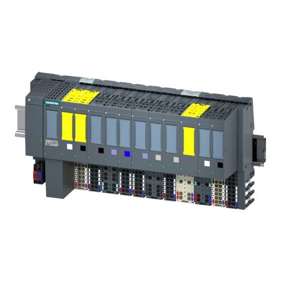
Product overview Properties Article number 6ES7134-6GD00-0BA1 View of the module Figure 2-1 View of the module AI 4×I 2-/4-wire ST Properties The module has the following technical properties: ● Analog input module with 4 inputs ● Measuring type current for 2-/4-wire transducers ●... - Page 9 ● Color identification labels ● Reference identification label ● Shield connector See also You will find additional information on the accessories in the ET 200SP distributed I/O system (http://support.automation.siemens.com/WW/view/en/58649293) system manual. Analog Input Module AI 4xI 2-/4-wire ST (6ES7134-6GD00-0BA1) Manual, 07/2014, A5E03551866-AC...
-
Page 10: Wiring Up
The first BaseUnit of a station must be a light-colored BaseUnit. Also keep this in mind during the configuration. See also You will find additional information on the BaseUnit types in the ET 200SP distributed I/O system (http://support.automation.siemens.com/WW/view/en/58649293) system manual. Analog Input Module AI 4xI 2-/4-wire ST (6ES7134-6GD00-0BA1) Manual, 07/2014, A5E03551866-AC... -
Page 11: Schematic Circuit Diagram
Wiring up 3.2 Schematic circuit diagram Schematic circuit diagram Schematic circuit diagram Figure 3-1 Schematic circuit diagram for AI 4×I 2-/4-wire ST Analog Input Module AI 4xI 2-/4-wire ST (6ES7134-6GD00-0BA1) Manual, 07/2014, A5E03551866-AC... -
Page 12: Parameters/Address Space
Parameters/address space Measuring types and ranges The analog input module AI 4xI 2-/4-wire ST has the following measuring ranges: Table 4- 1 Measuring ranges Measuring type Measuring range Resolution Current (2-wire transducer) 0 to 20 mA 15 bits 4 to 20 mA 15 bits Current (4-wire transducer) 0 to 20 mA... -
Page 13: Parameters
Parameters/address space 4.2 Parameters Parameters Parameters of the AI 4xI 2-/4-wire ST The effective range of the parameters depends on the type of configuration. The following configurations are possible: ● Central operation with an S7-1500 CPU ● Distributed operation on PROFINET IO in an ET 200SP system ●... - Page 14 Parameters/address space 4.2 Parameters Parameter Value range Default Configuration Effective range in RUN with configuration software, e.g. STEP 7 (TIA Portal) GSD file GSD file PROFINET IO PROFIBUS DP Smoothing none Channel Channel none • weak • medium • strong •...
-
Page 15: Explanation Of The Parameters
Parameters/address space 4.3 Explanation of the parameters Explanation of the parameters Diagnostics no supply voltage L+ Enabling of the diagnostics for no or insufficient supply voltage L+. Diagnostics short-circuit to ground Enabling of the diagnostics in the event of a short-circuit of the encoder supply to ground or of an input to the encoder supply. - Page 16 Potential group Specifies that a BaseUnit with voltage supply feed-in is located in this slot (see system manual ET 200SP Distributed I/O System (http://support.automation.siemens.com/WW/view/en/58649293)). Analog Input Module AI 4xI 2-/4-wire ST (6ES7134-6GD00-0BA1) Manual, 07/2014, A5E03551866-AC...
-
Page 17: Address Space
Parameters/address space 4.4 Address space Address space Configuration options The following configurations are possible: ● Configuration 1: Without value status ● Configuration 2: With value status Evaluating the value status If you enable the value status for the analog module, an additional byte is occupied in the input address space. -
Page 18: Interrupts/Diagnostics Alarms
Interrupts/diagnostics alarms Status and error display LED display The figure below shows the LED displays of the AI 4xI 2-/4-wire ST. ① DIAG (green/red) ② Channel status (green) ③ PWR (green) Figure 5-1 LED display Meaning of the LED displays The following tables show the meaning of the status and error displays. - Page 19 Interrupts/diagnostics alarms 5.1 Status and error display DIAG LED Table 5- 1 DIAG LED fault/error display DIAG LED Meaning Backplane bus supply of the ET 200SP not OK off Module parameters not assigned Flashes Module parameters assigned and no module diagnostics Module parameters assigned and module diagnostics Flashes Channel status LED...
-
Page 20: Interrupts
Interrupts/diagnostics alarms 5.2 Interrupts Interrupts The analog input module AI 4xI 2-/4-wire ST supports diagnostics interrupts. Diagnostics interrupt The module generates a diagnostics interrupt for the following events: ● Channel temporarily unavailable ● Short-circuit (current, 2-wire transducer) ● Wire break (current 4..20 mA) ●... -
Page 21: Diagnostics Alarms
Interrupts/diagnostics alarms 5.3 Diagnostics alarms Diagnostics alarms A diagnostics alarm is output for each diagnostics event and the DIAG LED on the module flashes. The diagnostics alarms can, for example, be read from the diagnostics buffer of the CPU. You can evaluate the error codes with the user program. Table 5- 4 Diagnostics alarms, their meaning and how to deal with them Diagnostics alarm... -
Page 22: Technical Specifications
Technical specifications Technical specifications Technical specifications of the AI 4×I 2-/4-wire ST 6ES7134-6GD00-0BA1 Product type designation AI 4xI 2-/4-wire ST General information Firmware version V1.1 Usable BaseUnits BU type A0, A1 Color code for module-specific color identification label CC03 Product function I&M data Engineering with STEP 7 TIA Portal can be configured/integrated as of version V11 SP2 / V13... - Page 23 Technical specifications 6.1 Technical specifications 6ES7134-6GD00-0BA1 Power loss Power loss, typ. 0.85 W; without encoder supply voltage Address area Address space per module Address space per module, max. 8 bytes; + 1 byte for QI information Analog inputs Number of analog inputs Maximum permitted input current for current input 50 mA (destruction limit)
- Page 24 Technical specifications 6.1 Technical specifications 6ES7134-6GD00-0BA1 Measured value smoothing Configurable Setting: None Setting: Weak Setting: Medium Setting: Strong Encoders Connection of the signal transmitters for current measurement as 2-wire transducer 650 Ω Load of the 2-wire transducer, max. • for current measurement as 4-wire transducer Errors/accuracies Linearity error (in relation to input range), (+/-) ±...
- Page 25 Between the inputs (UCM) 10 VDC Insulation Insulation tested with 707 VDC (type test) Dimensions Width 15 mm Weights Weight, approx. 31 g Dimension drawing See manual ET 200SP BaseUnits (http://support.automation.siemens.com/WW/view/en/58532597/133300) Analog Input Module AI 4xI 2-/4-wire ST (6ES7134-6GD00-0BA1) Manual, 07/2014, A5E03551866-AC...
-
Page 26: Parameter Data Record
Parameter data record Dependencies when configuring with GSD file When configuring the module with a GSD file, remember that the settings of some parameters are dependent on each other. Configuring with a PROFINET GSD file The table lists the properties and their dependencies on the measuring type and measuring range for PROFINET. -
Page 27: Parameter Assignment And Structure Of The Parameter Data Record
Parameter data record A.2 Parameter assignment and structure of the parameter data record Parameter assignment and structure of the parameter data record Parameter assignment in the user program The module can be re-configured in RUN (for example, the voltage or current values of selected channels can be changed in RUN without having an effect on the other channels). - Page 28 Parameter data record A.2 Parameter assignment and structure of the parameter data record Structure of data record 128 Note Channel 0 contains the diagnostics for the entire module. Figure A-1 Structure of data record 128 Header information The figure below shows the structure of the header information. Figure A-2 Header information Analog Input Module AI 4xI 2-/4-wire ST (6ES7134-6GD00-0BA1)
- Page 29 Parameter data record A.2 Parameter assignment and structure of the parameter data record Parameters The figure below shows the structure of the parameters for channels 0 to 3. You enable a parameter by setting the corresponding bit to "1". Figure A-3 Structure of byte x to x+17 for channels 0 to 3 Analog Input Module AI 4xI 2-/4-wire ST (6ES7134-6GD00-0BA1) Manual, 07/2014, A5E03551866-AC...
- Page 30 Parameter data record A.2 Parameter assignment and structure of the parameter data record Codes for the measuring type The following table contains the codes for the measuring types of the analog input module. You must enter these codes at byte x (see previous figure). Table A- 1 Codes for the measuring type Measuring type...
-
Page 31: Representation Of Analog Values
Representation of analog values This appendix shows the analog values for all measuring ranges that you can use with the analog module. Measured value resolution The resolution of the analog values differs depending on the analog module and its assigned parameters. The table below shows the representation of binary analog values and of the associated decimal and hexadecimal units of the analog values. -
Page 32: Representation Of Input Ranges
Representation of analog values B.1 Representation of input ranges Representation of input ranges In the following tables, you can find the digitized representation of the bipolar and unipolar input ranges. The resolution is 16 bits. Table B- 2 Bipolar input ranges Dec. -
Page 33: Representation Of Analog Values In The Current Measuring Ranges
Representation of analog values B.2 Representation of analog values in the current measuring ranges Representation of analog values in the current measuring ranges The following tables list the decimal and hexadecimal values (codes) of the possible current measuring ranges. Table B- 4 Current measuring range ±20 mA Values Current measuring range...