Table of Contents
Advertisement
Quick Links
Multiple Split type Air-Conditioners
TECHNICAL & SERVICE MANUAL
Series PEFY
<Indoor unit>
PEFY-P80VMH-E-F
Models
PEFY-P140VMH-E-F
PEFY-P200VMH-E-F
PEFY-P250VMH-E-F
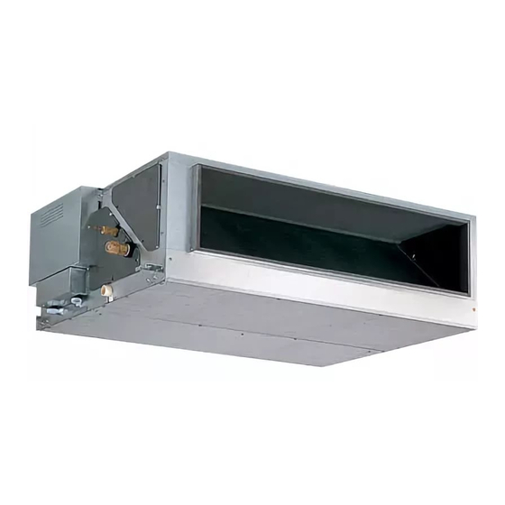
INDOOR UNIT
Ceiling Concealed (Fresh Air Intake type)
CONTENTS
SAFETY PRECAUTIONS ·························1
1. FEATURES ···········································3
2. PART NAMES AND FUNCTIONS ········4
3. SPECIFICATION ···································6
4. OUTLINES AND DIMENSIONS············8
5. WIRING DIAGRAM ·····························10
7. TROUBLE SHOOTING ·······················13
8. DISASSEMBLY PROCEDURE ··········· 16
For use with the R410A & R407C & R22
····
12
Advertisement
Table of Contents

Related Manuals for Mitsubishi Electric CITY MULTI PEFY-P80VMH-E-F


Summary of Contents for Mitsubishi Electric CITY MULTI PEFY-P80VMH-E-F
-
Page 1: Table Of Contents
Multiple Split type Air-Conditioners TECHNICAL & SERVICE MANUAL Ceiling Concealed (Fresh Air Intake type) Series PEFY <Indoor unit> PEFY-P80VMH-E-F Models PEFY-P140VMH-E-F PEFY-P200VMH-E-F PEFY-P250VMH-E-F CONTENTS SAFETY PRECAUTIONS ·························1 1. FEATURES ···········································3 2. PART NAMES AND FUNCTIONS ········4 3. SPECIFICATION ···································6 4. OUTLINES AND DIMENSIONS············8 5. -
Page 2: Safety Precautions
- Inadequate strength may cause the unit to fall down, resulting in is shorted and operated forcibly, or parts other than those specified injuries. by Mitsubishi Electric are used, fire or explosion may result. • Use the specified cables for wiring. Make the connections se- curely so that the outside force of the cable is not applied to the •... - Page 3 2. Precautions for devices that use R410A or R407C refrigerant Caution: • Do not use the existing refrigerant piping. - The old refrigerant and refrigerator oil in the existing piping con- tains a large amount of chlorine which may cause the refrigerator oil of the new unit to deteriorate.
-
Page 4: Features
FEATURES Ceiling Concealed Series PEFY Indoor unit Cooling capacity/Heating capacity Models PEFY-P80VMH-E-F 9.0 / 8.5 PEFY-P140VMH-E-F 16.0 / 15.1 PEFY-P200VMH-E-F 22.4 / 21.2 PEFY-P250VMH-E-F 28.0 / 26.5... -
Page 5: Part Names And Functions
PART NAMES AND FUNCTIONS G Indoor (Main) Unit Air outlet Air inlet G Remote controller [PAR-20MAA] Once the controls are set, the same operation mode can be repeated by simply pressing the ON/OFF button. [Operation buttons] CENTRALLY CONTROLLED 1Hr. ON OFF ˚C CLOCK CHECK... - Page 6 [Display] CENTRALLY CONTROLLED 1Hr. ON OFF ˚C CLOCK CHECK FILTER CHECK MODE ˚C TEST RUN STAND BY ERROR CODE FUNCTION NOT AVAILABLE DEFROST TEMP. ON/OFF I KL J Current time/Timer Centralized control Timer ON Abnormality occurs Operation mode: COOL, DRY, AUTO, FAN, HEAT...
-
Page 7: Specification
SPECIFICATION 3-1. Specification PEFY-P80VMH-E-F PEFY-P140VMH-E-F PEFY-P200VMH-E-F PEFY-P250VMH-E-F Power source ~ 220-240V 50Hz / ~ 208-230V 60Hz 3N~ 380-415V 50Hz / 60Hz ❇ 1 16.0 22.4 28.0 Cooling capacity ❇ 1 BTU/h 30,700 54,580 76,400 95,500 ❇ 1 15.1 21.2 26.5 Heating capacity ❇... - Page 8 3-2. Electrical parts specifications Model Symbol PEFY-P80VMH-E-F PEFY-P140VMH-E-F PEFY-P200VMH-E-F PEFY-P250VMH-E-F Parts name Tranrsformer (Primary) 50/60Hz 220-240V (Secondry) (23.5V 0.9A) Liquid pipe TH22 Resistance 0˚C/15kΩ,10˚C/9.6kΩ,20˚C/6.3kΩ,25˚C/5.4kΩ,30˚C/4.3kΩ,40˚C/3.0kΩ thermistor Gas pipe TH23 Resistance 0˚C/15kΩ,10˚C/9.6kΩ,20˚C/6.3kΩ,25˚C/5.4kΩ,30˚C/4.3kΩ,40˚C/3.0kΩ thermistor Outdoor air temperature TH24 Resistance 0˚C/15kΩ,10˚C/9.6kΩ,20˚C/6.3kΩ,25˚C/5.4kΩ,30˚C/4.3kΩ,40˚C/3.0kΩ thermistor Fuse FUSE 250V 6.3A (Indoor con- troller board)
-
Page 9: Outlines And Dimensions
OUTLINES AND DIMENSIONS PEFY-P80·140VMH-E-F Unit : mm... - Page 10 PEFY-P200· 250VMH-E-F Unit : mm...
-
Page 11: Wiring Diagram
WIRING DIAGRAM PEFY-P80·140VMH-E-F... - Page 12 PEFY-P200· 250VMH-E-F...
-
Page 13: Refrigerant System Diagram
REFRIGERANT SYSTEM DIAGRAM Gas pipe thermistor TH23 Gas pipe Liquid pipe thermistor TH22 Flared joints (Type 80·140) Brazed joints (Type 200·250) Heat exchanger Linear expansion valve Strainer (#100 mesh) Strainer (#100 mesh) Outdoor air temperature thermistor TH24 Capacity PEFY-P80VMH-E-F PEFY-P140VMH-E-F Item ø... -
Page 14: Trouble Shooting
TROUBLE SHOOTING 7-1. How to check the parts Parts name Check points Liquid pipe thermistor Disconnect the connector, then measure the resistance using a tester. (TH22) (Sorrounding temperature 10°C~30°C) Gas pipe thermistor (TH23) Normal Abnormal Outdoor air temperature (Refer to the thermistor characteristic graph) Ω... - Page 15 7-2. Setting of address switch Make sure that power source is turning off. Indoor unit control board S W 4 < At delivery (All models)> SW 1 S W 4 < At delivery (All models)> 1 2 3 4 5 6 7 8 9 10 0 1 2 3 4 5 6 7 8 9 9 10...
- Page 16 7-3. Setting of Dip-switch (at delivery) Models Dip-SW SW 1 S W 3 S W4 S W5 SW 7 220V PEFY-P80 240V 1 2 3 4 5 6 7 8 910 1 2 3 4 5 6 1 2 3 4 5 6 7 8 910 VMH-E-F 1 2 3 1 2 3...
-
Page 17: Disassembly Procedure
DISASSEMBLY PROCEDURE Be careful on removing heavy parts. 8-1. CONTROL BOX OPERATING PROCEDURE PHOTOS · Models 80 1.Removing the control box cover Fig.1 (1) Remove the fixing screws (two) of the control box (A), and remove the cover. (Fig. 1) *At this stage, the following servicing is possible. - Page 18 Be careful on removing heavy parts. OPERATING PROCEDURE PHOTOS · Models 200 Fig.4 1.Removing the control box cover (1) Remove the fixing screws (four) of the control box cover (C), and remove the cover. (Fig. 4) *At this stage, the following servicing is possible.(Fig. 5) 1 Operation and check of the switches (listed below) which are on the control board.
- Page 19 Be careful on removing heavy parts. 8-2. FAN and FAN MOTOR OPERATING PROCEDURE PHOTOS Models 80 • Fig.1 1.Removing the control box. (1) Remove the control box cover and terminal block cover with procedure 8-1. (2) Remove the fan motor connectors. (3) Remove the fixing screws (two) of the control box and slide the control box to remove.(Fig.
- Page 20 Be careful on removing heavy parts. OPERATING PROCEDURE PHOTOS (4) Slide the motor (A) with motor base (D) in direction of allow Fig.5 1 . (Fig. 5) Arrow 1 Fig.6 Motor (A) Model 140 *Motor maintenance procedure is almost 80 model procedure.
- Page 21 Be careful on removing heavy parts. OPERATING PROCEDURE PHOTOS Models 200· 250 Control box Fig.7 1.Removing the control box. cover 2 (1) Remove the control box cover1 with procedure 8-1. (2) Remove the fixing screws (four) of the control cover 2, and remove the control cover2.
- Page 22 Be careful on removing heavy parts. OPERATING PROCEDURE PHOTOS (3) After removing the fixing screws (H) (as shown models Fig.11 80, 140) of the front fan case (B) and remove the fan. Pull the fan case (B). (4) Remove the fixing screws (K) (three) of the bell mouse (J) attached fan case (L), and remove the bell mouse (J).
- Page 23 Be careful on removing heavy parts. 8-3. LEV,THERMISTOR (Liquid/Gas piping temperature detection) OPERATING PROCEDURE PHOTOS Models 80 • Fig.1 1.Removing the LEV. (1) Remove the control box cover with procedure 8-1. (2) Remove the fixing screws (four) of the heat exchanger cover (A), and remove the cover (A).(Fig.
- Page 24 Be careful on removing heavy parts. 8-4. HEAT EXCHANGER OPERATING PROCEDURE PHOTOS Models 80 • Fig.1 1.Removing the heat exchanger. (1) Remove the heat exchanger cover with procedure 8-3-1. Bottom plate (2) Remove the bottom plate which is air outlet side.(fixing screws : ten) (Fig.
- Page 25 Be careful on removing heavy parts. OPERATING PROCEDURE PHOTOS (4) Remove the maintenance cover.(fixing screws : two) (Fig. 4) Fig.4 (5) Remove the heat exchanger.(fixing screws : four) (Fig. 3,5) *Removerd heat exchanger is as shown Fig .6 Maintenance cover Fixing screws Fig.5 Fixing screws...
- Page 26 Be careful on removing heavy parts. OPERATING PROCEDURE PHOTOS · Models 200 Fig.7 1.Removing the heat exchanger. (1) Remove the refrigerant piping and drain hose from main Bottom plate unit.(Be care that water is not leaking from drain hose. ) (2) Remove the power supply wire and the transmission line.
- Page 27 Be careful on removing heavy parts. OPERATING PROCEDURE PHOTOS (7) Remove the fixing screws (three) of the heat exchanger Fig.10 cover, and remove the cover. Remove the fixing screws (four) of the maintenance cover, and remove the cover. (Fig. Fixing screws (7) Remove the heat exchanger.
- Page 28 8-5. CONTROL BOX INSIDE LAYOUT Models 80·140 Trans Condenser (for motor) Indoor unit FAN2 CN3T STR2012 FAN3 contoller board DSA board CN52 CN81 CN60 CN27 CN62 CN82 SW14 SW12 SW11 Transmission terminal block Power sourse Address board terminal block Models 200·250 Magnet contactor Trans FAN2...
- Page 29 8-6. SENSOR POSITION GPEFY-P80VMH-E-F GPEFY-P140VMH-E-F Liquid sensor Gas sensor Liquid sensor Gas sensor GPEFY-P200VMH-E-F GPEFY-P250VMH-E-F Liquid sensor Gas sensor Gas sensor Liquid sensor...
- Page 30 HEAD OFFICE: MITSUBISHI DENKI BLDG., 2-2-3, MARUNOUCHI, CHIYODA-KU, TOKYO 100-8310, JAPAN Issued in Sep. 2004 MEE04K286 New publication, effective Sep. 2004 Specifications subject to change without notice...