Advertisement
Quick Links
EVCO S.p.A. | EV3B33N7VXRX04 | Instruction sheet ver. 1.0 | Code 1043B33E103DRY | Page 1 of 2 | PT 27/18
EV3B33
N7VXRX04
E
ENGLISH
-
Power supply 230 VAC or 115 VAC (according to the model).
-
Exchanger probe (PTC/NTC).
-
Multi-purpose input.
-
Compressor relay 30 A res. @ 250 VAC.
-
Cooling or heating operation.
1
MEASUREMENTS AND INSTALLATION
Measurements in mm (inches). To be fitted to a panel, snap-in brackets provided.
INSTALLATION PRECAUTIONS
-
The thickness of the panel must be between 0.8 and 2.0 mm (1/32 and 1/16 in)
-
Ensure that the working conditions are within the limits stated in the TECHNICAL
SPECIFICATIONS section.
-
Do not install the device close to heat sources, equipment with a strong magnetic field,
in places subject to direct sunlight, rain, damp, excessive dust, mechanical vibrations
or shocks.
-
In compliance with safety regulations, the device must be installed properly to ensure
adequate protection from contact with electrical parts. All protective parts must be
fixed in such a way as to need the aid of a tool to remove them.
2
ELECTRICAL CONNECTION
N.B.
- Use cables of an adequate section for the current running through them.
- To reduce any electromagnetic interference connect the power cables as far away
as possible from the signal cables.
PRECAUTIONS FOR ELECTRICAL CONNECTION
If using an electrical or pneumatic screwdriver, adjust the tightening torque.
-
If the device has been moved from a cold to a warm place, the humidity may have
-
caused condensation to form inside. Wait about an hour before switching on the
power.
Make sure that the supply voltage, electrical frequency and power are within the set
-
limits. See the section TECHNICAL SPECIFICATIONS.
Disconnect the power supply before doing any type of maintenance.
-
-
Do not use the device as safety device.
For repairs and for further information, contact the EVCO sales network.
-
3
FIRST-TIME
1.
Install following the instructions given in the section MEASUREMENTS AND INSTALLA-
TION.
2.
Power up the device as shown in the section ELECTRICAL CONNECTION and an internal
test will be run.
The test normally takes a few seconds, when it is finished the display will switch off.
3.
Configure the device as shown in the section Setting configuration parameters.
Recommended configuration parameters for first-time use.
PAR.
DEF.
PARAMETER
P0
1
probe type
P2
0
temperature unit of measurement
r1
1.0
setpoint compressor off (after time
r3)
r2
8.0
setpoint compressor on
r3
10
consecutive time exchanger tempera-
ture lower than r1 for compressor off
r4
0
hot or cold mode regulation
Then check that the remaining settings are appropriate; see the section CONFIGURA-
TION PARAMETERS.
4.
Disconnect the device from the mains.
5.
Make the electrical connection as shown in the section ELECTRICAL CONNECTION with-
out powering up the device.
6.
Power up the device.
4
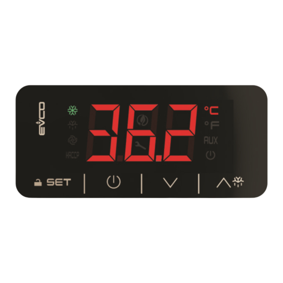
USER INTERFACE AND MAIN FUNCTIONS
Controller for refrigerator cycle dryer for compressed air
4.1
Switching the device on/off
1.
If the device is switched on, the display will show the exchanger temperature; if the display
shows an alarm code, see the section ALARMS.
LED
ON
compressor on
reserved
condenser fan on
reserved
HACCP
- low consumption ac-
tive
- compressor off
- request for compres-
sor service
- request
service
view temperature
°C/°F
water pump on
AUX
device off
If 30 s have elapsed without the keys being pressed, the display will show the "Loc" label and
the keypad will lock automatically.
4.2
Unlock keypad
Touch a key for 1 s: the display will show the label "UnL".
4.3
Switching off the alarm output (if u0 or u1 = 2 and A7 = 1)
Touch a key.
5
ADDITIONAL FUNCTIONS
5.1
View/delete compressor and device functioning hours
Check that the keypad is not locked.
1.
2.
LAB.
hSE
rhS
hFI
rhF
rFI
3.
4.
5.
6.
5.2
View the temperature detected by the probes
Check that the keypad is not locked.
1.
2.
LAB.
Pb1
Pb2
3.
4.
5.3
Evacuation valve test
Check that the keypad is not locked.
1.
6
SETTINGS
6.1
Setting configuration parameters
1.
2.
3.
4.
5.
6.
MIN... MAX.
0 = PTC
1 = NTC
7.
0 = °C
1 = °F
-99 °C/°F... r2
8.
r1... 99 °C/°F
9.
0... 90 min
0 = cold mode
6.2
Restore the factory settings (default) and store customized settings as default
1 = hot mode
N.B.
- Check that the factory settings are appropriate; see the section CONFIGURATION
PARAMETERS.
- the storing of customized settings overwrites the default.
1.
2.
3.
VAL.
149
161
4.
5.
6.
7.
8.
Interrupt the power supply to the device.
9.
If POF = 1, touch the ON/STAND-BY key for 4 s.
OFF
FLASHING
compressor off
compressor protection active
-
-
condenser fan off
-
-
-
-
-
-
-
for
device
-
-
water pump off
-
device on
device on/off active
Touch the DOWN key for 4 s.
Touch the UP or DOWN key within 15 s to select a label.
DESCRIPTION
view compressor functioning hours
delete compressor functioning hours
view device functioning hours
delete device functioning hours
reset clogged filter alarm
Touch the SET key.
Touch the UP or DOWN key to set "149" (for selection rhF and
rFI) or "171" (for selection rhS).
Touch the SET key.
Touch the ON/STAND-BY key (or do not operate for 60 s) to exit
the procedure.
Touch the DOWN key for 4 s.
Touch the UP or DOWN key within 15 s to select a label.
DESCRIPTION
exchanger temperature
condenser temperature
Touch the SET key.
Touch the ON/STAND-BY key (or do not operate for 60 s) to exit
the procedure.
Touch the UP key for 4 s: the valve will be switched on till the
key release, then it will cyclically work again.
Touch the SET key for 4 s: the display will show the label "PA".
Touch the SET key.
Touch the UP or DOWN key within 15 s to set the PAS value (de-
fault "10").
Touch the SET key (or do not operate for 15 s): the display will
show the label "CA1".
Touch the UP or DOWN key to select a parameter.
Touch the SET key.
Touch the UP or DOWN key within 15 s to set the value.
Touch the SET key (or do not operate for 15 s).
Touch the SET key for 4 s (or do not operate for 60 s) to exit the
procedure.
Touch the SET key for 4 s: the display will show the label "PA".
Touch the SET key.
Touch the UP or DOWN key within 15 s to set the value.
DESCRIPTION
value to restore the factory settings (default)
value to store customized settings as default
Touch the SET key (or do not operate for 15 s): the display will
show the label "dEF" (when value "149" is set) or the label
"MAP" (when value "161" is set).
Touch the SET key.
Touch the UP or DOWN key within 15 s to set "4".
Touch the SET key (or do not operate for 15 s): the display will
show for 4 s "- - -" flashing, then the device will exit the proce-
dure.
Touch the SET key 2 s before action 6. to exit the procedure be-
forehand.
7
CONFIGURATION PARAMETERS
N.
PAR.
DEF.
ANALOGUE INPUTS
1
CA1
0.0
exchanger probe offset
2
CA2
0.0
condenser probe offset
3
P0
1
probe type
4
P1
0
enable °C decimal point
5
P2
0
temperature unit of measure-
ment
6
P3
0
input Pb1 function
7
P4
5
display refresh time
N.
PAR.
DEF.
REGULATION
8
r1
1.0
setpoint compressor off (after
time r3)
9
r2
8.0
setpoint compressor on
10
r3
10
consecutive time exchanger tem-
perature lower than r1 for com-
pressor off
11
r4
0
cooling or heating operation
12
r5
0.0
threshold for low temperature
display lock
13
r6
5.0
threshold for high temperature
display lock
14
r7
1
enable display lock
N.
PAR.
DEF.
COMPRESSOR
15
C1
1
compressor on delay after pow-
er-on
16
C2
0
compressor off minimum time
17
C3
0
compressor on minimum time
18
C4
0
compressor off time during ex-
changer probe alarm
19
C5
10
compressor on time during ex-
changer probe alarm
20
C6
80.0
threshold for high condensation
warning
threshold for high condensation
21
C7
90.0
alarm
22
C8
1
high condensation alarm delay
23
C9
0
count mode
24
C10
200
compressor hours for service
25
C11
20
suction temperature alarm delay
N.
PAR.
DEF.
ALLARMS
26
A0
1.0
A1, A3, C6 and F1 reset differen-
tial
27
A1
0.0
threshold for low temperature
alarm
28
A2
1
enable low temperature alarm
29
A3
15.0
threshold for high temperature
alarm
30
A4
1
enable low temperature alarm
31
A5
1
high/low temperature alarms de-
lay
32
A6
2
high/low temperature alarm de-
lay after power-on
33
A7
0
alarm output mode
34
A8
0
count mode
35
A9
200
compressor hours for service
N.
PAR.
DEF.
FANS
36
F0
15.0
threshold for condenser fan on
37
F1
30
condenser fan off delay after
compressor off for suction tem-
perature alarm
N.
PAR.
DEF.
DIGITAL INPUTS
38
i0
1
multi-purpose 2 input activation
39
i1
1
funzione ingresso configurabile
40
i2
0
multi-purpose 2 input activation
41
i3
0
funzione ingresso multi-purpose
1
42
i4
0
high pressure alarm delay
43
i5
0
clogged filter alarm delay
44
i6
0
condenser fan on delay from di-
gital input
45
i7
30
clogged filter alarm delay after
power-on
N.
PAR.
DEF.
DIGITAL OUTPUTS
46
u0
2
configuration auxiliary output 1
47
u1
1
configuration auxiliary output 2
48
u2
5
time evacuation valve on
49
u3
4
time evacuation valve off
N.
PAR.
DEF.
ENERGY SAVING (if r4 = 0)
50
HE1
0
consecutive time without operat-
ing on keys for low consumption
51
HE2
3
configuration energy saving LED
(options 0 and 1) and compres-
sor mode during normal opera-
tion (options 2 and 3)
MIN... MAX.
-25... 25 °C/°F
-25... 25 °C/°F
0 = PTC
1 = NTC
0 = no
1 = yes
0 = °C
1 = °F
0 = exchanger probe
1 = exchanger probe + high
pressure input (in series,
activation with contact
open)
0... 250 s : 10
MIN... MAX.
-99 °C/°F... r2
if r4 = 1, setpoint compressor
on
r1... 199 °C/°F
if r4 = 1, setpoint compressor
off (after time r3)
0... 90 min
if r4 = 1, consecutive time
exchanger temperature ower
than r2 for compressor ofm
0 = cooling
1 = heating
-99... r6 °C/°F
r5... 99 °C/°F
0 = no
1 = yes
MIN... MAX.
0... 240 min
0... 240 min
0... 240 s
0... 240 min
0... 240 min
0... 199 °C/°F
differential A0
0... 199 °C/°F
0... 15 min
0 = device hours
1 = compressor hours
0... 999 h x 100
0 = disabled
0... 60 min
MIN... MAX.
0.1... 15 °C/°F
-99... A3 °C/°F
0 = no
1 = yes
A1... 99 °C/°F
0 = no
1 = yes
0... 240 min
0... 99 min x 10
0 = with alarm active
1 = with alarm active and
inactive touching a key
0 = device hours
1 = compressor hours
0... 999 h x 100
0 = disabled
MIN... MAX.
0... 99 °C/°F
differential A0
0... 240 s
MIN... MAX.
0 = with contact closed
1 = with contact open
0 = disabled
1 = HP/HPr alarm
2 = FIL alarm
3 = condenser fan on
4 = tSH alarm
5 = device off
6 = condenser probe
0 = with contact closed
1 = with contact open
0 = disabled
1 = HP/HPr alarm
2 = FIL alarm
3 = condenser fan on
4 = tSH alarm
5 = device off
0... 240 s
0... 999 min
0... 240 s
0... 999 s
MIN... MAX.
0 = disabled
1 = evacuation valve
2 = alarm
3 = condenser fan
4 = water pump
0 = disabled
1 = evacuation valve
2 = alarm
3 = condenser fan
4 = water pump
0... 240 s
0... 240 s
MIN... MAX.
0... 240 min
0 = disabled
0 = LED energy saving on in
low consumption
1 = LED energy saving on if
compressor off
2 = compressor on, off in
HP, tAL and tAH alarm
3 = compressor on, off in HP
alarm
Advertisement

Related Manuals for Evco EV3B33N7VXRX04


Summary of Contents for Evco EV3B33N7VXRX04
- Page 1 EVCO S.p.A. | EV3B33N7VXRX04 | Instruction sheet ver. 1.0 | Code 1043B33E103DRY | Page 1 of 2 | PT 27/18 EV3B33 Controller for refrigerator cycle dryer for compressed air N7VXRX04 Switching the device on/off CONFIGURATION PARAMETERS If POF = 1, touch the ON/STAND-BY key for 4 s.
- Page 2 EVCO S.p.A. | EV3B33N7VXRX04 | Instruction sheet ver. 1.0 | Code 1043B33E103DRY | Page 2 of 2 | PT 27/18 PAR. DEF. SAFETIES MIN... MAX. enable ON/STAND-BY key 0 = no 1 = yes password -99... 999 user interface LEDs configuration...
Need help?
Do you have a question about the EV3B33N7VXRX04 and is the answer not in the manual?
Questions and answers