Advertisement
Advertisement

Related Manuals for Erbe ICC 50


Summary of Contents for Erbe ICC 50
- Page 1 ERBE ICC 50 ICC 80 ICC BIPOLAR 08.99...
- Page 3 ICC 50, ICC 80, ICC BIPOLAR Service manual 10122-003, 10122-008, 10122-010, 10122-040, 10122-041 10122-100, 10122-101, 10122-102, 10122-103, 10122-104 10122-054, 10122-055, 10122-060, 10122-061 08.99...
- Page 4 ERBE Elektromedizin GmbH. The information contained in this service manual may be revised or extended without prior notice and represents no obligation on the part of ERBE Elektromedizin GmbH. Copyright © ERBE Elektromedizin GmbH, Tübingen1999 Printed by: ERBE Elektromedizin GmbH, Tübingen Art.
-
Page 5: Table Of Contents
Contents Chapter Title Page Table of contents ....................5 Test programs ...................... 7 ERROR list ......................17 Adjustment and testing instructions ..............25 Circuit diagrams ....................33 Appendix and addresses ..................53 / 58... -
Page 7: Test Programs
CHAPTER 1 Test programs... - Page 9 Test programs ICC 50, ICC 80, ICC BIPOLAR No. Test program function 1 Basic setting of the front panel 2 Calling up the Error list 3 Programming the required activation time limitation 4 Activation of all visual front panel displays...
- Page 10 The ICC units are equipped with a system for error detection, error indication and error memory. Every error is labelled with an error number (ERROR No.). The ICC 50, ICC 80 and ICC BIPOLAR units store the last 20 ERROR numbers. Test program 2 indicates the stored ERROR numbers. The most recent error is in Memory location 1.
- Page 11 Test programs ICC 50, ICC 80, ICC BIPOLAR Range: 1…99 seconds. This value must be stored in memory by pressing the CUT effect key for about 3 seconds. Refer to Test program 1. It is possible to exit the test program without saving a new value to memory by briefly pressing the CUT effect key.
- Page 12 Test programs ICC 50, ICC 80, ICC BIPOLAR By pressing the CUT effect button, the voltage is decreased to 50 volts. By pressing the CUT effect key again, the test program is exited. Test program 12 Adjustment of the phase control for the HF generator This adjustment is made as the generator idles, but with the monopolar patient lines connected.
- Page 13 Test programs ICC 50, ICC 80, ICC BIPOLAR At the NE socket a resistance of 260 ohms is connected via a standard NE cable. Then the reference value for the NE monitoring is automatically adjusted by the unit, which is indicated by the appearance of an unbroken line (»—«) in the COAG display and the illumination of both the red and the green NE LEDs.
- Page 14 Test programs ICC 50, ICC 80, ICC BIPOLAR Verification of the modulation timer and the modulation monitor (»t.t.«) At the test program start, the timer is initialized and switched on. Activation using the CUT footswitch turns on the generator (with the output relay open) and the feedback is measured. In the COAG display, the measurement value for the feedback is indicated.
- Page 15 1 Test programs / 58...
-
Page 17: Error List
CHAPTER 2 ERROR list... - Page 19 Troubleshooting for ICC family equipment The ICC equipment family is equipped with an error detection system which records the last 20 (ICC 50, ICC 80, ICC BIPOLAR) errors in an ERROR list and saves them in memory. This error memory can be called up via Test program no.
- Page 20 ERROR nos. 1–13 Error no. Explanation and remedy Activation time limit reached. If the activation time limit has been set too short, extend this by using Test program no. 3. During monopolar activation, the NE monitor produces an impermissible value. Check whether the NE is correctly applied and connected to the unit.
- Page 21 ERROR nos. 14–25 Error Explanation and remedy Incorrect dosage during CUT: Voltage 20% too high. Equipment error: Tech. Service. Incorrect dosage during FORCED: 20% too high. Equipment error: Tech. Service. Incorrect dosage during SOFT or BIPOLAR: Voltage 20% too high. Equipment error: Tech.
- Page 22 ERROR nos. 26–64 Error No. Explanation and remedy »COAG« mode scroll key pressed when switching on the unit or defective. Check whether the corresponding key was pressed before switching on the unit. If not: Front panel or unit defective, Tech. Service. »Up«...
- Page 23 ERROR nos. 65–93 Error Explanation and remedy 65–79 (not assigned.) Error when checking the power supply unit (Test program 11): Voltage too low. Equipment error: Tech. Service. Error when checking the power supply unit (Test program 11): Voltage too high. Equipment error: Tech.
-
Page 25: Adjustment And Testing Instructions
CHAPTER 3 Adjustment and testing instructions... - Page 27 The following instructions for adjustment of HF surgical units ICC 50, ICC 80 and ICC BIPOLAR allow the service technician to perform all adjustment work. This adjustment work must only be performed by the manufacturer or by third parties expressly authorized to do this by the manufacturer in consideration of the particular safety requirements for electromedical equipment.
- Page 28 ICC 50, ICC 80, ICC BIPOLAR An essential component of the ICC 50, ICC 80 and ICC BIPOLAR unit is the microcontroller (68HC11A1), which directly influences almost all functions of equipment and unifies a large number of functions through its capabilities.
- Page 29 Adjustment and testing instructions ICC 50, ICC 80, ICC BIPOLAR Basic initialization Attach the shorting bridge to J7. Switch the unit on. At the same time, basic initialization is automatically performed insofar as this has not already occurred with the respective microcontroller.
- Page 30 Adjustment and testing instructions ICC 50, ICC 80, ICC BIPOLAR Setup of the phase control for the HF generator Connect the monopolar patient lines with no load. This is important for a precise setup! Connect the oscilloscope and probe at MP4 to MP5. Probe 100:1 recommended.
- Page 31 Adjustment and testing instructions ICC 50, ICC 80, ICC BIPOLAR Calibration of the HF power output Connect the monopolar patient lines to the HF power meter (APM 600). Activate Test program 13 (only possible in Special Test Mode, see above).
-
Page 33: Circuit Diagrams
CHAPTER 4 Circuit diagrams... - Page 35 ICC 50...
- Page 36 240V 230V 120V AC_2A 100V AC_2B B250C5000 MUR120 0R56 5:40 V_REF 68nF 68nF +15V IC19 100k 7667 LM3524 +15V V_DAC 2N3440 100k IC20 IC19 LM324 7667 Shut- down LM324 I_GL IC20 I_PK F_MOD IC17 +15V IC18 +15V IC18 +15V GEN_EN &...
- Page 37 Art. No. 80116-251 08 / 99 REL1 REL1 REL2 REL2 Bipolar REL_1 REL_2 REL1 REL2 +15V BA159 22nF +15V 30122-021 100R BA159 IC22 IC21 BC517 30122-021 CNY66 CNY66 100R IC20 BC517 NE_ANA LM324 1N4148 AC_2A +15V T0.5A 78xx +15V BC547 $wert 100uF AC_2B...
- Page 38 DATABUS IC16 MOD_ON GEN_ON GEN_ON IC14 ADRBUS RESET BC557 E_CLK D0-D7 A0-A15 MASK_1 MASK_2 & & OUT_1 RESET MASK_3 74HC00 74HC00 MASK_4 & TL431 RES_1 74hc20 74HC273 IC13 IC12 ADRBUS E_CLK REL_1 ULN2004A DATABUS GATE MOD_ON REL_2 D0-D7 OUT_0 GEN_EN GEN_ON PE0/AN0 PC0/AD0...
- Page 39 ICC 50 Mainboard 40122-011 gelb yellow orange orange lila purple schwarz black braun brown MASSE GROUND Ausg. Issue Schaltbilder / 58...
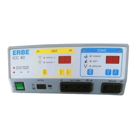
- Page 41 ICC 80...
- Page 42 240V 230V 120V AC_2A 100V AC_2B B250C5000 MUR120 0R56 5:40 V_REF 68nF 68nF +15V IC19 100k 7667 LM3524 +15V V_DAC 2N3440 100k IC20 IC19 LM324 7667 Shut- down LM324 I_GL IC20 I_PK F_MOD IC17 +15V IC18 +15V IC18 +15V GEN_EN &...
- Page 43 Art. No. 80116-251 08 / 99 REL1 REL1 REL2 REL2 Bipolar REL_1 REL_2 REL1 REL2 +15V BA159 22nF +15V 30122-021 100R BA159 IC22 IC21 BC517 30122-021 CNY66 CNY66 100R IC20 BC517 NE_ANA LM324 1N4148 AC_2A +15V T0.5A 78xx +15V BC547 $wert 100uF AC_2B...
- Page 44 DATABUS IC16 MOD_ON GEN_ON GEN_ON IC14 ADRBUS RESET BC557 E_CLK D0-D7 A0-A15 MASK_1 MASK_2 & & OUT_1 RESET MASK_3 74HC00 74HC00 MASK_4 & TL431 RES_1 74hc20 74HC273 IC13 IC12 ADRBUS E_CLK REL_1 ULN2004A DATABUS GATE MOD_ON REL_2 D0-D7 OUT_0 GEN_EN GEN_ON PE0/AN0 PC0/AD0...
- Page 45 ICC 80 Mainboard 40122-011 gelb yellow orange orange lila purple schwarz black braun brown MASSE GROUND Ausg. Issue Schaltbilder / 58...
- Page 47 ICC BIPOLAR...
- Page 48 240V 230V 120V AC_2A 100V AC_2B B250C5000 MUR120 0R56 5:40 V_REF 68nF 68nF +15V IC19 100k 7667 LM3524 +15V V_DAC 2N3440 100k IC20 IC19 LM324 7667 Shut- down LM324 I_GL IC20 I_PK F_MOD IC17 +15V IC18 +15V IC18 +15V GEN_EN &...
- Page 49 Art. No. 80116-251 08 / 99 REL1 Bipolar REL1 REL1 IC20 REL_1 NE_ANA LM324 AC_2A +15V T0.5A 78xx +15V BC547 $wert 100uF AC_2B BC557 FS_A & MASK_1 74hc00 SND_AL BS170 Fusschalter FS_B BC557 & MASK_2 Footswitch 74hc00 & +15V 750R Coag FOOT_A F.COMP...
- Page 50 DATABUS IC16 MOD_ON GEN_ON GEN_ON IC14 ADRBUS RESET BC557 E_CLK D0-D7 A0-A15 MASK_1 MASK_2 & & OUT_1 RESET MASK_3 74HC00 74HC00 MASK_4 & TL431 RES_1 74hc20 74HC273 IC13 IC12 ADRBUS E_CLK REL_1 ULN2004A GATE MOD_ON DATABUS REL_2 D0-D7 OUT_0 GEN_ON GEN_EN PE0/AN0 PC0/AD0...
- Page 51 ICC BIPOLAR Mainboard 40122-011 gelb yellow orange orange lila purple schwarz black braun brown MASSE GROUND Ausg. Issue Schaltbilder / 58...
-
Page 53: Appendix And Addresses
CHAPTER 5 Appendix and Addresses... - Page 55 Appendix ATTENTION The unit contains a lithium battery which can only be disposed of in old battery collection containers when completely discharged! Otherwise make certain that a short circuit is prevented! 5 Appendix and addresses / 58...
- Page 56 Your notes...
Need help?
Do you have a question about the ICC 50 and is the answer not in the manual?
Questions and answers