JBL EON15-G2 Technical & Service Manual
Hide thumbs
Also See for EON15-G2:
- Technical manual (34 pages) ,
- User manual (24 pages) ,
- Specifications (4 pages)
Advertisement
Table of Contents
- 1 Table of Contents
- 2 Product Overview
- 3 Specifications/Frequency Response Graphic
- 4 Panel Controls, Connectors and Indicators
- 5 Block Diagram
- 6 Circuit Descriptions
- 7 Troubleshooting Guide
- 8 Semiconductor Diagrams
- 9 Final Test Procedure
- 10 Pictorials of Pcb Assemblies
- 11 Jbl Warranty Limited Warranty
- Download this manual
Advertisement
Table of Contents

Related Manuals for JBL EON15-G2


Summary of Contents for JBL EON15-G2
- Page 1 Technical Service Manual Rev. A 7/16/2004...
-
Page 2: Table Of Contents
SPECIFICATIONS/FREQUENCY RESPONSE GRAPHIC PANEL CONTROLS, CONNECTORS AND INDICATORS BLOCK DIAGRAM CIRCUIT DESCRIPTIONS TROUBLESHOOTING GUIDE SEMICONDUCTOR DIAGRAMS FINAL TEST PROCEDURE PICTORIALS OF PCB ASSEMBLIES JBL WARRANTY LIMITED WARRANTY 26 - 65 SYSTEM EXPLODED VIEW FAILURE QA CODES SCHEMATICS / MASTER PARTS LIST... -
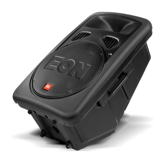
Page 3: Product Overview
Product Overview... -
Page 4: Specifications/Frequency Response Graphic
Rest assured that your JBL Professional equipment will always equal or exceed the published design specifications unless... -
Page 5: Panel Controls, Connectors And Indicators
Connectors, Controls and Indicator... -
Page 8: Block Diagram
EON15 G2 Block Diagram... -
Page 9: Circuit Descriptions
AC Input Module The main line voltage is connected at input jack P1 on the ac input PCB. Capacitors C2 and C3 work in conjunction with C1 to help reduce the instantaneous line voltage spikes that cause static noise in the high frequency range. - Page 10 Power Supply Initially, raw alternating current enters the EON15-G2 from the IEC connector on the AC input PCB and is directly connected to the power switch SW1 through the main fuses F1 & F2. Toggling SW2 directs the ac voltage to travel to the voltage selector switch that allows the customer to select between 120V or 230V.
- Page 11 Loop/Mix Input Circuitry Shown above is the Input Loop/ Mixture Circuitry with the accompanying Channel 2 and 3 Input and Equalization Circuits for the EON 15-G2. NOTE: It is assumed that the technician is familiar with the main XLR input circuit for this discussion. Balanced input signal enters the ¼”...
- Page 12 Signal Input Circuitry Voltage measurements are at frequency of 100 Hz with –20 dB on input at XLR (J2). Balanced input is connected to J2 and travels to impedance selector switch SW2. This switch inserts R33, R52 and R45 for line level inputs and removes same for microphone level inputs. It also shorts the “mic”...
- Page 13 Signal Peak LED Circuitry This is the signal indication circuitry for the EON15-G2 that is located on the signal input PCB. The presence of signal, the peak input signal and/or instantaneous signal overmodulation from both the high frequency and low frequency amplifiers is shown.
- Page 14 High Frequency Signal Processing Voltage measurements are at frequency of 10Khz with –25dB on input at XLR (not shown). Shown above is the high frequency signal processing circuitry for the EON 15-GII. Input audio signal is transferred from the input PCB to the Main Amplifier PCB via multi-pin connector cable. . Specifically, pin 1 of WH1 carries this signal to pin 1 of connector P1.
- Page 15 Voltage measurements are at frequency of 10Khz with –25dB on input at XLR (not shown). This is the high frequency power amplifier used in the EON15-G2 after serial number 27225. It uses a TDA7293 operational power amplifier in a non-inverting configuration with the normal peripheral components to provide proper equalization and operation.
- Page 16 Low Frequency Signal Processing Voltage measurements are at frequency of 100 Hz with –20 dB on input at XLR (not shown). Shown above is the low frequency signal processing circuitry for the EON 15-G2. Signal of .7Vpp enters from pin 1 of P1 to the serially connected low pass filters U4-A and U4-B. The signal diverges to U4-C and U4-D where the upper limit (midpoint 110.7Hz) and the lower limit (midpoint 62.2 Hz) are enhanced and summed by U3-D.
- Page 17 LF Amplifier Stage All Voltage measured with reference to audio ground with no input signal The low frequency amplifier uses discrete components configured in a push-pull drive architecture operating in the class AB region and have a measurable gain of 18.52 dB. The voltage rails for the power amplifier are ±40 Vdc as rectified by bridge BR1 located in the Power Supply Module.
-
Page 18: Troubleshooting Guide
If product status is out of warranty, troubleshoot and contact the customer with an estimate of the repair charges. In either case, it is always wise to use the original JBL replacement components that are listed in the master parts list to insure the maximum performance of JBL equipment. To obtain more ordering information contact the website at www.JBLPRO.com. - Page 19 No sound (possible missing control voltage) Verify ±15Vdc at P1 pins 3 & 4 on input/output PCB TROUBLESHOOTING THE EON15-G2 (cont.) No sound (voltages are okay), The quickest way to isolate this problem to a specific PCB is to start with a known good input /output PCB.
- Page 20 If mute pin 10 of HF output IC reads close to –15Vdc, recheck above results and signal trace PCB. The unit is detecting a fault or there exists a problem with the fault detection circuitry. Signal and voltage trace accordingly using circuit description. Low output power problems Verify proper operating voltages as above under “No Voltage.
-
Page 21: Semiconductor Diagrams
Semiconductors... -
Page 22: Final Test Procedure
EON15-G2 Final Test Procedure INITIAL POWER UP TEST Setup—Serially connect a variac, isolation transformer and ammeter. Connect unit under test to variac. Mic /Line switch should be Line position. Volume control at fully CCW position and no load. • Slowly increase the variac output voltage monitoring for excessive current usage •... -
Page 23: Pictorials Of Pcb Assemblies
EON15 G2 Pictorial Of Power Input PCB Assembly Component Parts List Item Part No. Description Ref.Des 32-1244 Con Plug AC Receptacle 3 Pin 44-0004 Switch Power 453-13222-00 Fuse 3.15 A Time Lag, 5X20 mm F1,F2 44-0015 Switch Voltage Select 115V /230V 62-0049 Cap 1000 pf Cer 250 V 20% C2,C3... - Page 24 EON15 G2 Pictorial Of Input PCB Assembly Component Parts List Item Part No. Qty. Description Ref.Des. Item Part No. Qty. Description Ref.Des. 72-1439 IC 5532 SM 32-0119 Con, Jack, ¼ Phono J3,J4 72-1480 IC NJM 4580 SM U1-U3-U4-U5 72-4034 IC LM339,Comparator 40-0083 Pot 5K C 9mm Horiz 70-0038...
- Page 25 EON15 G2 Pictorial Of Output PCB Assembly Component Parts List Item Part No. Qty. Description Ref.Des. Item Part No. Qty. Description Ref.Des. 70-0032 XSTR 2SA1302 PNP Q21,Q20 72-0021 IC TDA 7293 70-0033 XSTR 2SB186A PNP Q16,Q17, 72-1450 IC TL074 U2,U5 70-0034 XSTR 2SD1763A NPN Q15,Q13,Q11...
-
Page 26: Jbl Warranty Limited Warranty
Click here to view the JBL Limited Warranty Statement http://www.jblpro.com/pub/technote/warranty.pdf Click here for the Systems Exploded View / Mechanical Assembly Drawings http://www.jblproservice.com/pdf/EON-G2%20Series/EON15G2.pdf Click here to view the JBL Professional QA Codes http://www.jblproservice.com/protected/Domestic%20pdf/Electronic%20QA%20Codes.pdf http://www.jblproservice.com/protected/Domestic%20pdf/Loudspeakers%20and%20Loudspeaker%20System%20QA%20Codes.pdf Click here for the Main Board Schematics http://www.jblproservice.com/pdf/EON-G2%20Series/EON15-G2%201st%20Version%20Main%20Amp%20Schematics.pdf... - Page 27 Click here for the Control Board Schematic http://www.jblproservice.com/pdf/EON-G2%20Series/EON15-G2%20Control%20Board%20Schematics.pdf Click here for the EQ Board Schematic http://www.jblproservice.com/pdf/EON-G2%20Series/EON15-G2%20EQ%20Board%20Schematic.pdf Click here for the Input/Output/Control/EQ Boards Parts List http://www.jblproservice.com/pdf/EON-G2%20Series/EON15-G2%20Input-Output-Control%20and%20EQ%20Board%20Parts%20List.pdf Click here for the A/C Input Module Schematic http://www.jblproservice.com/pdf/EON-G2%20Series/EON15-G2%20AC%20Input%20Module%20Schematic.pdf Click here for the A/C Input Module Parts List...
- Page 29 JBL Incorporated, 8500 Balboa Boulevard, P.O. Box 2200, Northridge, California 91329 U.S.A. Technical Manual JBL EON15-G2 SPECIFICATIONS ACOUSTIC & ELECTRICAL SPECIFICATIONS: SYSTEM COMPONENTS: (CONT’D) • Power Capacity: 300 Watts @ Low Frequency • Input 2 & 3 Sensitivity: -18 dBu to +20 dBu for Rated Output Driver Impedance.
- Page 30 JBL EON15-G2 Amplifier PCA Transformer Clip, Christmas Tree 321814-001 LED Assembly (Supplied with AMP) BLACK F .187 - F .250 + L.F. Tree Mount Tie (Woofer/Baffle) 925-0000-00 WHITE F .205 - BLUE H.F. (2418H-1) F .250 + AC Power Input, PCA...
- Page 31 JBL EON15-G2 Srew (12) Rear Enclousure AC Power Assy 904902-010 EON15-G2 Screw (18) EON15-G2 MS, PPH 380-90019-00 804-41110-20 10-16 x .63 ZINC 250-00001-01 10-32 x 1 1/4 Baffle Assy PAN, PH, BLK With Cone Label, 120V EON15-G2LF EONG2 Screw (2)
- Page 32 JBL EON15-G2 Baffle (Ref) Handle EON15 923-00025-00 SLV, Gap 340-20000-90 Terminal Plug B2 362-10009-00 Screw (2) 900401-020 MS, PPH V/C Assy, EON-G2 10-32 x 1.25 BLK 220-27005-00 Driver, High Freq 2418H-1 Diaph Repl D8R2418-1 Clip Christmas Tree, 321814-001 TPLT/BPLT EON15...
- Page 33 Network failures should continue to use the transducer failure codes. Please utilize these codes on every warranty claim submitted to JBL Professional. Exclusion of these codes will result in the return of warranty claims.
- Page 34 JBL PROFESSIONAL ELECTRONIC FAILURE Q.A. CODES July 1, 2004 Page 1 Q.A. DESCRIPTION OF DEFECT WARRANTY Q.A. DESCRIPTION OF DEFECT WARRANTY CODE STATUS CODE STATUS 10.052 Capacitor - Burned due to Workmanship/Design 10.010 IC (Specify) 10.011 IC - Open 10.053 Capacitor - Shorted 10.012 IC - Burned due to Workmanship/Design...
- Page 35 JBL PROFESSIONAL ELECTRONIC FAILURE Q.A. CODES July 1, 2004 Page 2 Q.A. DESCRIPTION OF DEFECT WARRANTY Q.A. DESCRIPTION OF DEFECT WARRANTY CODE STATUS CODE STATUS 10.113 Switch - Will Not Close 10.172 Transformer - Burned due to Workmanship/Design 10.114 Switch - Noisy 10.173 Transformer - Noisy...
- Page 36 JBL PROFESSIONAL ELECTRONIC FAILURE Q.A. CODES July 1, 2004 Page 3 Q.A. DESCRIPTION OF DEFECT WARRANTY Q.A. DESCRIPTION OF DEFECT WARRANTY CODE STATUS CODE STATUS 10.602 Adjust Bias 10.603 Adjust Meter 10.604 Adjust Chassis 10.700 MISC/HARDWARE (Specify) 10.701 Screw - Missing (from factory) 10.702 Screw - Broken (from factory)
- Page 37 JBL PROFESSIONAL LOUDSPEAKERS AND LOUDSPEAKER SYSTEM Q.A. CODES July 1, 2004 Page 1 Q.A. DESCRIPTION OF DEFECT WARRANTY Q.A. DESCRIPTION OF DEFECT WARRANTY CODE STATUS CODE STATUS No Defects - Definition 3.11 Open – Break at Eyelet No Defects - Unclassified 3.12...
- Page 38 External Damage – No Salvageable Parts 11.0 MISCELLANEOUS 6.11 External Damage - Diaphragm 6.12 External Damage - Broken Terminal 11.1 Not JBL Cone/Coil Assembly/Diaphragm 6.13 External Damage - Broken Grille 11.2 Missing Cone/Coil Assembly 6.14 External Damage - Hardware 11.3 Missing Diaphragm Assembly 11.4...
- Page 39 JBL EON15-G2...
- Page 40 JBL EON15-G2...
- Page 41 JBL EON15-G2...
- Page 42 JBL EON15-G2...
- Page 43 JBL EON15-G2...
- Page 44 JBL EON15-G2...
- Page 55 JBL EON15-G2...
- Page 56 JBL EON15-G2...
- Page 57 JBL EON15-G2...
- Page 58 JBL EON15-G2...
- Page 59 JBL EON15-G2...
- Page 60 JBL EON15-G2...
Need help?
Do you have a question about the EON15-G2 and is the answer not in the manual?
Questions and answers