Advertisement
Quick Links
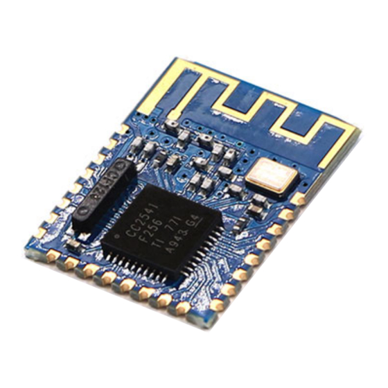
Bluetooth V4.0 HM-11 BLE Module
Contents
1 Introduction
2 Features
3 Specification
4 Electrical Characteristics
5 Pin definition
6 AT commands & Configuration
7 Example Code
Introduction
This is a SMD BLE module used in our BLE Bee and Xadow BLE. It is based on TI cc2541 chip, enables robust network
nodes to be built with low total bill-of-material costs and highly suited for ultralow power consumption systems. The
module is small and easy to use, with the preprogrammed firmware of manufacturer, you could quickly build BLE
communications via its AT command. Supporting BLE communications with iphone, ipad and Android 4.3.
Features
Bluetooth protocol: Bluetooth Specification V4.0 BLE
Working frequency: 2.4 GHz ISM band
Interface way: a serial port
Open environment within 30 meters can realize communication between modules
To send and receive no byte limit between modules
Modulation method: GFSK (Gaussian Frequency Shift Keying)
Transmission power: - DBM, 23-6 DBM, 0 DBM, 6 DBM, can be modified by the AT command
use TI CC2541 chip, configuration space of 256 KB, support the AT command, the user can according to need to
change the role (master, slave mode) and the serial port baud rate, name of equipment, matching parameters
such as passwords, use agile.
power supply: + 3.3 VDC 50 mA
working temperature: - 5 ~ + 65 Centigrade
Specification
Specification
Microprocessor
Resources
↑
TOP
Outline Dimension
Power supply
Communication Protocol
IO counts
Key input IO
LED Indicators IO
Connectivity
User Manual
CC2541
Support the AT command, the user can according to need to change the role
(master, slave mode) and the serial port baud rate,name of equipment,Matching
parameters such as password, the use of flexible.
13.5mm x 18.5mm x 2.3mm
3.3V
Uart(3.3V LVTTL)
2
1
1
Socket compatible with XBee
Value
Advertisement

Subscribe to Our Youtube Channel
Related Manuals for Arduino HM-11


Summary of Contents for Arduino HM-11
- Page 1 Bluetooth V4.0 HM-11 BLE Module User Manual Contents 1 Introduction 2 Features 3 Specification 4 Electrical Characteristics 5 Pin definition 6 AT commands & Configuration 7 Example Code Introduction This is a SMD BLE module used in our BLE Bee and Xadow BLE. It is based on TI cc2541 chip, enables robust network nodes to be built with low total bill-of-material costs and highly suited for ultralow power consumption systems. The module is small and easy to use, with the preprogrammed firmware of manufacturer, you could quickly build BLE communications via its AT command. Supporting BLE communications with iphone, ipad and Android 4.3. Features Bluetooth protocol: Bluetooth Specification V4.0 BLE Working frequency: 2.4 GHz ISM band Interface way: a serial port Open environment within 30 meters can realize communication between modules To send and receive no byte limit between modules Modulation method: GFSK (Gaussian Frequency Shift Keying) Transmission power: - DBM, 23-6 DBM, 0 DBM, 6 DBM, can be modified by the AT command use TI CC2541 chip, configuration space of 256 KB, support the AT command, the user can according to need to change the role (master, slave mode) and the serial port baud rate, name of equipment, matching parameters such as passwords, use agile. power supply: + 3.3 VDC 50 mA working temperature: - 5 ~ + 65 Centigrade Specification Specification Value Microprocessor CC2541 Support the AT command, the user can according to need to change the role Resources (master, slave mode) and the serial port baud rate,name of equipment,Matching ↑ parameters such as password, the use of flexible. Outline Dimension 13.5mm x 18.5mm x 2.3mm...
- Page 2 Electrical Characteristics Specification Unit Max Input Voltage -0.3 Working Input Voltage Transmit Current Receive Current Deep Sleep Current Operating Temperature °C Pin definition Name Description UART_RTS UART UART_TX UART UART_CTS UART UART_RX UART Power supply 3.3V RESETB Reset, active low at least in 5ms PIO3 IO port, used for connect to DHT11/DS18B20 PIO2 Digital input, output PIO1 LED indicator PIO0 Button pin AT commands & Configuration 1) Query the native MAC address Send: AT + ADDR? Send after a successful return: OK + LADD: MAC address (address for 12 string)
- Page 3 2) Query the baud rate Send: AT+BAUD? Send after a successful return: OK + Get: [para1] Scope of para1:0 ~ 8. The parameters corresponding to: 0 represents 9600, 1, 2, 9600, 38400, on behalf of the representative representative of 57600, 115200, 5, 4800, 6, 7 represents 1200, 1200 2400. The default baud rate to 9600. 3) Set the baud rate Send: AT+BAUD[para1] Send after a successful return: OK+Set:[para1] Example: send: AT + BAUD1, return: OK + Set: 2.The baud rate is set to 19200. Note: after the switch to the 1200, module will no longer support the configurations of the AT command, and press the PIO0 under standby, module can restore the factory Settings.Do not recommend using the baud rate.After setting the baud rate, modules should be on electricity, anew set parameters can take effect. 4) from the device connected to the bluetooth address specified Send: AT+CON[para1] Send after a successful return: OK+CONN[para2] Para2 range is: A, E, F Example: from the bluetooth address is: 0017EA0943AE, sending the AT + CON0017EA0943AE, module returns: OK + CONNA or OK + + CONNF CONNE or OK. 5) removal equipment matching information Send: AT + CLEAR Send after a successful return: OK + CLEAR Clear success had connected device address code information. 6) query module working mode Send: AT + MODE? Send after a successful return: OK + Get: [para] Para: the range of 0 ~ 2. 0 represents passthrough mode, on behalf of the PIO acquisition + remote control + 1 passthrough, 2 representative passthrough + remote control mode.The default is 0. 7) set module working mode: Send: AT + MODE [] Send after a successful return: OK + Set: [para] 8) query device name Send: AT + NAME? Send after a successful return: OK + NAME [para1] 9) set the device name Send: AT + NAME [para1] Send after a successful return: OK + Set: [para1] Example: Set the device name to Seeed, sending the AT + NAMESeeed, return OK + Set: Seeed AT this time, the name of the bluetooth module has been changed to Seeed. Note: after the instruction execution, required to electricity, set the parameters of the approval. 10) query matching password Send: AT + PASS? ...
- Page 4 14) set the master-slave mode Send: AT + ROLE [para1] Send after a successful return: OK + Set: [para1] Example Code //master This example code is in the public domain. */ #include <SoftwareSerial.h> SoftwareSerial mySerial(2, 3); // RX, TX void setup() // Open serial communications and wait for port to open: Serial.begin(9600); while (!Serial) { ; // wait for serial port to connect. Needed for Leonardo only } Serial.println("Goodnight moon!"); // set the data rate for the SoftwareSerial port mySerial.begin(9600); // set master mySerial.print("AT+ROLE1"); delay(10000); void loop() // run over and over // set the data rate for the SoftwareSerial port mySerial.print("test I am master "); delay(10000); if (mySerial.available()) Serial.write(mySerial.read()); if (Serial.available()) mySerial.write(Serial.read()); //slave This example code is in the public domain. */ #include <SoftwareSerial.h> SoftwareSerial mySerial(2, 3); // RX, TX void setup() // Open serial communications and wait for port to open: Serial.begin(9600); while (!Serial) { ; // wait for serial port to connect. Needed for Leonardo only } Serial.println("Goodnight moon!");...
Need help?
Do you have a question about the HM-11 and is the answer not in the manual?
Questions and answers